1. Introduction
The lithium-ion batteries (LiBs) are currently the most promising energy storage device in a broad range of applications including electric vehicles as well as portable electronics. There is an increasing demand for the higher energy density of LiBs. One of approaches to meet the ever-growing demand for increasing the energy density is to substitute the existing electrode materials with high-capacity materials [1–4]. Silicon (Si) is considered as one of the most promising materials due to its high theoretical specific capacity (3579 mAh g−1 based on the formation of the Li15Si4 alloy), which is greatly higher than that of graphite (372 mAh g−1, LiC6). However, Si has crucial drawbacks for the commercial application in current LiBs due to the serious volume change (~300%) during alloying/de-alloying reaction with Li and its low electrical conductivity, resulting in the rapid capacity fading during cycling [5,6]. Numerous strategies have been applied to mitigate the above-mentioned problems for Si-based anodes, including Si size control, surface coating, active/inactive alloy, void space control and composites, etc. (refer to recent review paper) [7–11]. Of all the strategies, the approach of carbon/Si composites (CSC) attracts a great deal of interest because it is believed to enhance the electrical conductivity and also accommodate the huge volume changes. It is known, however, that in practical LiBs, there is little room for swelling arising from volume expansion of electrodes [12–14]. The expansion of CSC during charging is strongly dependent on the fraction of Si in CSC, and thus the Si content of CSC needs to be low enough to accommodate the volume change caused by Si, while resulting in a decrease in capacity of a CSC anode.
In addition, according to previous report [15], it appears that the specific capacity of LiBs can be significantly improved when the current anode material of graphite is replaced with anode materials having higher specific capacities compared with conventional graphite anodes.
In this work, we have prepared CSC anode materials having capacity of ~ 500 mAh g−1 as substitute for the existing graphite and investigated its electrochemical performance as an anode material for LiBs. The core-shell graphite@Si-graphite nanosheet-carbon composites were synthesized as a CSC anode material. In particular, considering the practical standard, the CSC electrodes for electrochemical evaluation were fabricated with water-based SBR-CMC binder as in the conventional graphite anode.
2. Experimental
The core-shell graphite@Si-graphite nanosheet-carbon composites (abbreviated to ‘core-shell composite’) were prepared as follows. A mixture of nano-Si (99.9%, D50 = ~100 nm, Nanostructured & Amorphous Materials Inc.), graphite nanosheets (D50 = 10 μm) and a petroleum pitch (carbon yield, 64%) powders was mixed with a tetrahydrofuran solution in which the pitch as carbon precursor was dissolved, and then vacuum-dried at 100°C for 10 h. The dried mixture was coated on spherical natural graphite (SNG, POSCO Chemical Co. Ltd., D50 = 16 μm) as the core particle. The process for shell coating was carried out by using a homemade mixer/agglomerator. The heat-treatment for carbonization of pitch was performed under an argon atmosphere at 1000°C.
The particle morphology and cross-section were examined by scanning electron microscopy (SEM) with energy dispersive x-ray (EDX) equipment. The phase information of the core-shell composite powders was investigated using powder X-ray diffractometry (XRD) with Cu Kα radiation.
Electrodes for electrochemical measurements were prepared as follows. Slurries containing 95 wt.% active material, 1 wt.% carbon black and 2 wt.% styrene butadiene rubber (SBR) and 2 wt.% carboxymethyl cellulose (CMC) as a binder, dissolved in distilled water. The obtained slurries were coated onto a copper foil that acts as a current collector. The loading was fixed at ~ 5 mg cm−2. The fabricated electrodes were dried at 180°C for 12 h under vacuum and then pressed.
The electrochemical performance of the prepared composites was investigated using lithium half-cell system based on CR2032 coin-type cell. The electrolyte was 1M LiPF6 dissolved in a mixed solvent of ethylene carbonate (EC) and diethyl carbonate (DEC) (1:1 by volume) with 10 vol % of fluoroethylene carbonate (FEC) (ENCHEM Co. Ltd, Korea). The cells were galvanostatically charged (lithiation) in constant current-constant voltage (CC-CV) and discharged (de-lithiation) under a constant current (CC) within the voltage window of 0.01 and 1.0 V at 0.3 C rate at 30°C. To examine the electrode swelling behavior, the thickness change at different charge-discharge cycles was also measured in micro-scale with a micrometer.
3. Results and Discussion
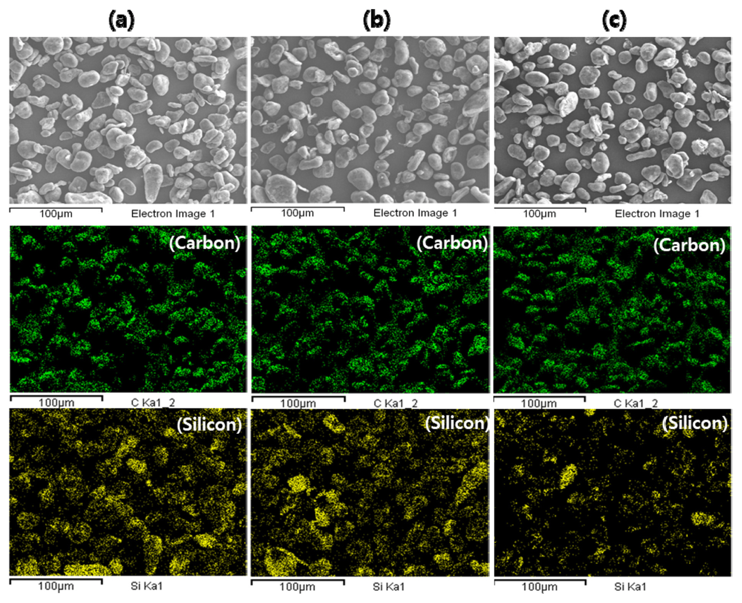
The SEM images of nano-Si and graphite nanosheets, used for shell coating, and spherical natural graphite as the core particle are shown in Fig. 1(a), (b) and (c), respectively. The thickness of graphite nanosheets was between 20 and 50 nm, as shown in inset Fig. 1(b). The core-shell composite material was prepared in three different weight ratios as listed in Table 1. From the SEM images of the core-shell composite particles and corresponding elemental mappings of carbon and silicon shown in Fig. 2, the resultant core-shell composite particles show a spherical morphology and the silicon is uniformly distributed amongst core-shell composite particles. Fig. 3 shows cross-sectional SEM images of the core-shell composite material, composite C-II. It is seen that the silicon particles are distributed between graphite nanosheets and between graphite nanosheet and graphite core particle, which are bound using pitch carbon as the conductive binder as schematically described in Fig. 3c.
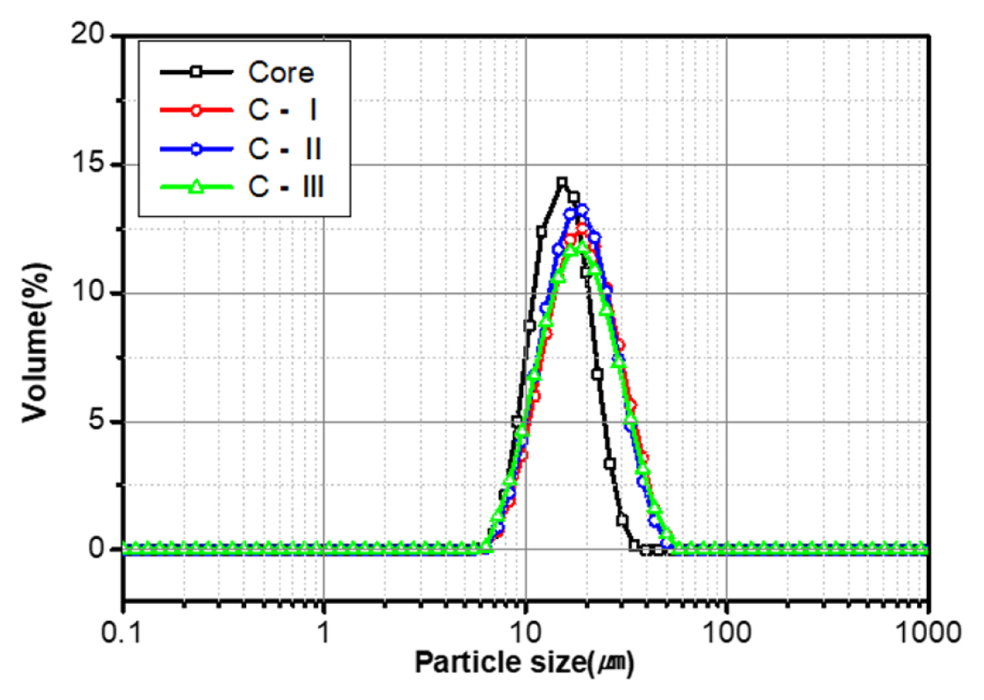
Fig. 4 compares the paricle size distributions of the spherical natural graphite used as core particle and core-shell composite materials. The distribution of core-shell composite materials shifts from the core material to the larger size, indicating that the mixture of nano-Si and graphite nanosheets are well adhered to the surface of the core particles.
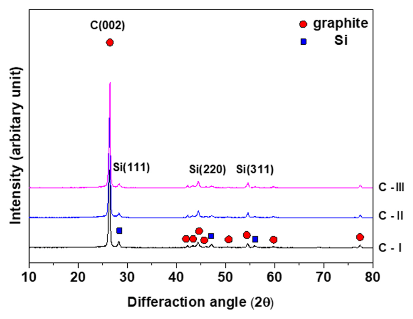
The XRD patterns of core-shell composite materials are shown in Fig. 5. Only the crystalline diffraction peaks of the silicon and graphite are observed, which shows that any impurity phase such as SiC has not been formed during preparation of core-shell composite materials.
The charge-discharge curves of core-shell composite samples during the first and second cycles are shown in Fig. 6. During the discharge (delithiation) process, there is a voltage plateau at around 0.4 V, corresponding to the de-alloying of Li15Si4 [11,16]. It appears that the capacity related with the plateau increases as the silicon content in the composite materials increases, and the specific capacity of core-shell composite materials is correspondingly high. The reversible capacity was 535, 505 and 478 mAh g−1 for C-I, C-II and C-III, respectively. On the other hand, three composite samples show the similar initial coulombic efficiency of around 90%.
The cycling performances of C-I, C-II and C-III electrodes are presented in Fig. 7. In particular, the C-III electrode exhibits an excellent performance compared with other electrodes, showing 99.2% capacity retention after 100 cycles (Fig. 7b). In addition, the coulombic efficiency of C-II and C-III electrodes quickly increases to 99.5% within the first five cycles and then reaches 99.8%, while C-I electrode takes 80 cycles to reach above 95% as shown in Fig. 7c. Fig. 8 illustrates the charge-discharge voltage profiles of the C-I, C-II and C-III electrodes at the 10th, 50th and 100th cycle. In the case of electrodes with a higher Si content, especially C-I, the voltage plateau at around 0.4 V during discharge gradually decreases in the subsequent cycles, resulting in a capacity fade during the cycling. However, the C-III electrode shows a stable discharge plateau, indicating an excellent cycling stability. It is also notable that the polarization, as measured by the voltage drop at the cut-off voltage for the discharge reaction, increases significantly with cycling for C-I electrode but remains almost unchanged from the 10th to the 100th cycle for the C-III electrode, representing enhanced structural stability of the C-III electrode.
It is well known that the degradation of Si-based electrodes during cycling is attributed to mainly two mechanisms of the electrical disconnection between electrode components, such as active materials and current collector, and the continuous formation of solid electrolyte interphase (SEI) layer. Therefore, the capacity retention of Si-based electrodes during cycling has been expressed in terms of cumulated relative irreversible capacities (RIC) defined as the ratio between the irreversible capacity loss and the delivered charge capacity [17]. The cumulated loss of RIC(disconnection) related with electrical disconnection and RIC(SEI) associated with SEI formation are demonstrated as a function of cycle for the C-I, C-II and C-III electrodes (Fig. 9). The irreversibility related to the SEI formation is comparable to each other, although it is a little bit larger in the C-I electrode than in the C-II and C-III electrodes (Fig. 9a). However, there is a distinct difference between those electrodes concerning the irreversible capacity loss related with electrical disconnection, as shown in Fig. 9b. The irreversible capacity loss is getting higher with cycling in the C-I electrode, while there is no noticeable increase in the C-III electrode. It therefore appears that the capacity fading during cycling of the C-I electrode is mainly due to an irreversible capacity loss caused by electrical disconnection. This is consistent with the results described above, e.g., the polarization increase and 0.4 V plateau capacity decrease during cycling observed in the C-I electrode.
The electrode thickness change after 50 cycles was illustrated for both lithiated and de-lithiated states (Fig. 10a). Considering that the degree of expansion increases with the reversible capacity, or the Si content in the composite, the electrode thickness change was also normalized by the reversible capacity measured at the first cycle (Fig. 10b), which shows similar behavior to Fig. 10a. As expected, the C-III electrode exhibits the lowest expansion rate of 23% in the de-lithiated state and 42% in the lithiated state. It is worth noting here that the gap between the electrode thickness changes after charge and discharge reaction appears to be 9, 12 and 19% for the C-I, C-II and C-III electrodes, respectively. In general, when an electrode is discharged, lithium ions could not be extracted from active materials isolated through electrical disconnection, resulting in still swollen state even after discharge process. Therefore, the C-I electrode, having a relatively high degree of the irreversibility related with electrical disconnection as shown in Fig. 9b, reveals a relatively small difference in electrode expansion rate between charged and discharged states. In contrast, the C-III electrode shows its mechanical resilience and can accommodate the volume change of electrode during cycling.
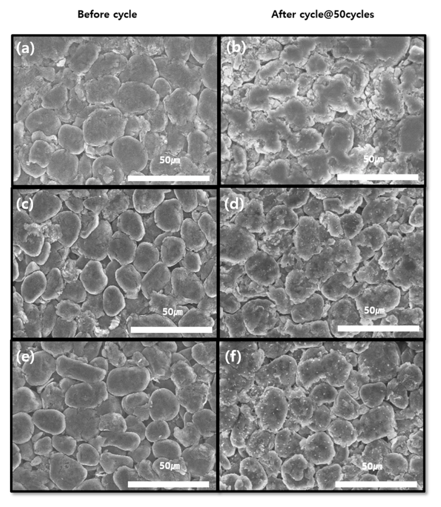
This relatively poor performance of the C-I electrode, containing a higher Si content than the other electrodes, could be attributed the following reasons: (i) some nano-Si particles are not wrapped in graphite nanosheets and exposed to electrolyte and (ii) some nano-Si particles are aggregated and electrically disconnected during cycling. On the other hand, the well-designed core-shell composite, in which the silicon particles are uniformly distributed in a pitch carbon matrix between graphite nanosheets and between graphite nanosheet/graphite core particle, can result in the excellent electrochemical performance as in the C-III electrode. It should be noted here that the electrochemical measurements were performed using electrodes with 4 wt% SBR-CMC binder in a high electrode density (~ 1.6 g cm−3), which is comparable to commercial graphite anodes. Fig. 11 shows the surface morphology of the C-I, C-II and C-III electrodes before and after 50 cycles. After 50 cycles, no cracks are formed in all the electrodes, and, especially in the C-III electrode, there is no signature of mechanical damage in the composite particles. At this point, it would be important to mention the effect of the graphite nanosheet on the electrode swelling. The electrode thickness change during cycling of a core-shell composite, in which the shell is composed of a mixture of nano-Si and a pitch carbon without graphite sheets, is compared with that of the C-II and C-III composites (Fig. 12). It should be noted here that the reversible capacity of the core-shell composite (490 mAh g−1) was comparable with that of the C-II and C-III composites. The electrode thickness change was measured at the lithiated state. Both C-II and C-III electrodes exhibited milder electrode expansion trends than the core-shell composite with a shell not containing graphite nanosheets.
Given that the difference is the presence of graphite nanosheets in shell, the less significant electrode expansion in C-II and C-III electrodes can be attributed to the buffering role of graphite nanosheets in shell of the core-shell composite. These results indicate that the heterostructure of core-shell composite, prepared by forming a shell composed of a mixture of nano-Si, graphite nanosheets and a pitch carbon on a spherical natural graphite particle, is very effective in buffering the volume change of Si during cycling.
4. Conclusions
In summary, we designed and fabricated a novel core-shell composite, having a reversible capacity of ~ 500 mAh g−1, by forming a shell composed of a mixture of nano-Si, graphite nanosheets and a pitch carbon on a spherical natural graphite particle. Due to the unique structure of nano-Si effectively wrapped by highly conductive and flexible graphite nanosheets in a shell, nano-Si particles are allowed to expand freely without mechanical constrain during lithiation and thus the core-shell composites can accommodate the volume change of electrode during charge and discharge. As a result, we have achieved a reversible capacity of ~ 500 mAh g−1 with the initial coulombic efficiency of 90%. The core-shell composites show the outstanding cycling stability in an electrode prepared in an electrode density of ~ 1.6 g cm−3 with 4 wt% SBR-CMC binder. The heterostructure of core-shell composites appears to be very effective in buffering the volume change of Si during cycling.