1. Introduction
Consumer electronics, electric vehicles (EVs), and smart grid energy storage (system have relied) on batteries with a high energy density, long cycle life, and low cost [1,2]. Lithium (Li) metal anode offers an extremely high theoretical specific capacity (3860 mAh g−1) and ideal electrochemical potential (−3.04 V vs. standard hydrogen electrode), and thus, which is regarded as the most promising anode material for next-generation high-energy-density batteries, such as Li-S and Li-air batteries [3]. However, the high cost, constant dendritic Li growth on the copper (Cu) current collector surface, and low coulombic efficiency (CE) associated with Li-metal anode result in poor cycle stability and safety hazards; therefore, these issues should be resolved for facilitating the practical applications of Li-metal anode. Efforts to address these challenges include the use of artificial solid electrolyte interphases (SEIs) [4], three-dimensional (3D) hosts [5–10], interlayers between Li and the separator [11], electrolyte additives [12–17], highly concentrated electrolytes [3,13], and solid-state batteries (SSBs) [1,3,18–20].
The trade-off between the safety and energy density of Li-metal anode has inspired the development and design of batteries with zero-excess Li, often referred to as anode-free Li-metal batteries (AFLMBs). As the cathode is less sensitive to moisture and air and there is no metallic Li in the cell, fabrication process can be achieved more easily using this platform. In addition, the AFLMBs are compatible with the current manufacturing infrastructures used for Li ion batteries (LIBs). Furthermore, the fabrication cost can be reduced compared to that of conventional LIBs because a graphite anode and expensive N-methyl-2-pyrrolidone (NMP) solvent are not required.
The AFLMBs can be operated following procedures: Initially, all of the active Li+ ions in AFLMBs are stored in the cathode material. During the initial charging process, Li+ ions are extracted from the cathode to the anode, and plated directly on the bare Cu current collector. During discharging, the deposited metallic Li is oxidized, and then the active Li+ ions intercalate back into the cathode. However, the electrochemical performance of AFLMBs is poor due to the absence of fresh Li to replenish the lost Li during cycling. In addition, dendritic Li growth and volume fluctuation during cycling are fatal issues that cause poor cycle and safety problem. To circumvent these concerns, several researches have mainly focused on designing functional electrolytes [21,22]. However, although the electrolyte approach verified the usefulness of controlling deposition morphology of Li and chemical composition of SEI layer, most of electrolytes are based on the ether-solvent, and thus it is indeed vulnerable to stability and oxidation at high voltage operation. Therefore, the carbonate-based functional electrolyte needs to be developed for stable cycling of AFLMBs.
To resolve the aforementioned concerns, this study aimed to investigate the feasibility of a LiPF6+LiFSI dual-salt carbonate-based electrolyte system with appropriate additives for uniform Li plating morphology during cell cycling. The extended lifespan and enhanced coulombic efficiency (CE) were achieved using a LiFSI+LiPF6 dual-salt electrolyte and demonstrated that the blended functional electrolyte can improve the surface stability at the anode side in the carbonate/ester co-solvent with appropriate additives. Electrochemical evaluation and comprehensive characterization revealed that not only a dense and relatively uniform Li layer was formed on a Cu foil current collector, but a stable and compact SEI film was also formed on the deposited Li in the blended electrolyte system, which contributed to the interfacial stability at the anode side, and eventually improving the electrochemical performances of AFLMBs.
2. Experimental
2.1. Electrolyte preparation
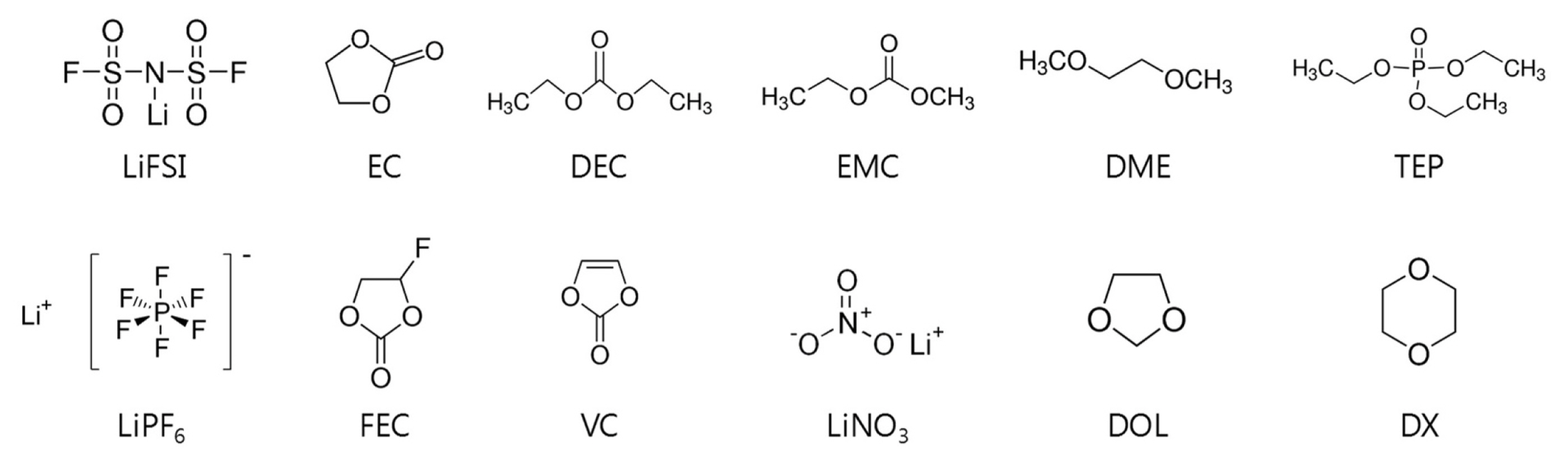
The LiPF6 and LiFSI salts were dissolved in various solvents or combinations thereof, including ethylene carbonate (EC), diethyl carbonate (DEC), and ethyl methyl carbonate (EMC), as carbonate-based solvents, and triethyl phosphate (TEP) as an ester-based solvent. In addition, 1,3-dioxolane (DOL), 1,4-dioxane (DX), and dimethyl ether (DME) were also evaluated as solvents, and fluoroethylene carbonate (FEC), vinylene carbonate (VC), and LiNO3 were used as additives. Specifically, eleven electrolytes were prepared, namely x M LiPF6 in EC/DEC/EMC (3:5:2 v/v, x =1, 2, 3, 4) with 5 wt% FEC and 2 wt % VC, and y M LiFSI in DOL/DME (1:1 v/v, y = 1, 2, 3, 4) with 2 wt % LiNO3 as single-salt electrolyte systems, and x M LiPF6 + y M LiFSI (x+y = 1, 2, 3, 4) in EC/DEC/EMC (3:5:2 v/v) with 5 wt% FEC, 2 wt% VC, and x M LiPF6 + y M LiFSI (x+y = 1, 2, 3, 4) in EC/DEC/EMC/TEP (1.5:2.5:1:5 v/v/v/v) with 5 wt% FEC, 2 wt% VC, and 2 wt% LiNO3 as dual-salt electrolyte systems. The additives were used to improve the cycling stability of the AFLMBs. Electrolyte preparation was conducted in an Ar-filled glove box with an O2 concentration of < 0.5 ppm and H2O concentration of < 0.5 ppm.
2.2. Electrochemical measurements
AFLMB full cells (Cu foil/LiFePO4 (LFP) or Cu foil/LiNi0.8Co0.1Mn0.1O2 (NCM811)), half cells (Cu foil/Li foil), and symmetric cells (Li foil/Li foil) were evaluated using coin-type cells (CR2032, Hohsen Corp.). AFLMB full cells were assembled using bare Cu foil as the anode substrate (i.e., anode current collector), LFP or NCM811-coated Al foil as the cathode material, and a monolayer polypropylene (PP) membrane (Celgard 2500) as the separator in the prepared carbonate-based electrolyte. All cell assembly and disassembly were conducted in an Ar-filled glove box.
2.3. Characterization
The morphology of the Li plating on the Cu substrate in the AFLMB full cell (LFP/Cu) and half cell (Cu foil/Li metal) was observed using scanning electron microscopy (SEM; S-4800, Hitachi, Japan) at an acceleration voltage of 15 kV. Electrochemical impedance spectroscopy (EIS) of the cells was performed using AFLMBs in the fully discharged state at different cycle numbers within a frequency range of 0.01 to 100,000 Hz at a perturbation amplitude of ±10 mV. The EIS measurements were acquired using a modular battery testing system (BCS-815, Biologic Science Instruments Ltd., France) coupled with a frequency response analyzer.
The compositions of the surface deposits on cycled AFLMB electrodes were examined by X-ray photoelectron spectroscopy (XPS) (ESCALAB 250, Thermo VG Scientific, England) using Al Kα radiation (hν = 1486.6 eV) as the X-ray source. The energy scale was calibrated against the C 1s peak at 284.6 eV and the spectra were fitted using XPS peak software.
3. Results and Discussion
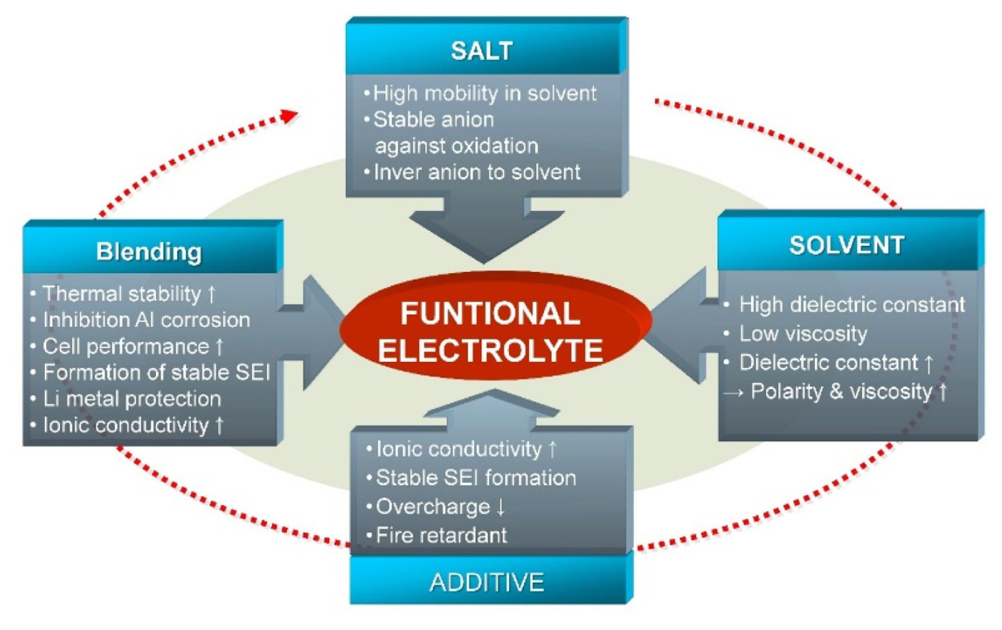
The electrolyte and additives used in a battery are dependent on the system’s requirements, thus the electrolyte have been adjusted as new battery systems are developed (Fig. 1). The electrolyte salt, electrolyte solvent, and additives must offer efficient transport of the Li ions from the anode to the cathode during charging, and vice versa during discharging. Specifically, the salt must offer high mobility in the solvent, and the solvents should have a high dielectric constant to dissolve the salts and additives. In addition, the additives have to form a stable solid electrolyte interface layer. Each component plays a critical role in forming a functional electrolyte system, and the overall electrolyte can be optimized based on a combination of components.
Generally, in the AFLMBs, the Li stored in the cathode must be plated on the current collector during the first charging process. This significantly differs from the plating on the Li-metal anode itself, as the current collector typically has a high interface energy with Li. This can lead to overpotential, thereby affecting the morphology of deposited Li and subsequent SEI formation, even leading to dendrite formation. The operation of a AFLMB system relies on uniform electrodeposition of Li from the cathode material and electrolyte onto the surface of the Cu current collector via an electrochemical reaction, where the morphology of the electrodeposited Li is highly dependent on the type of electrolyte. The requirements of electrolytes listed in Fig. 1 were satisfied in this study by developing an optimized electrolyte system for AFLMBs based on the blending of LiPF6 and LiFSI salts and additives in various types of solvents (Fig. 2).
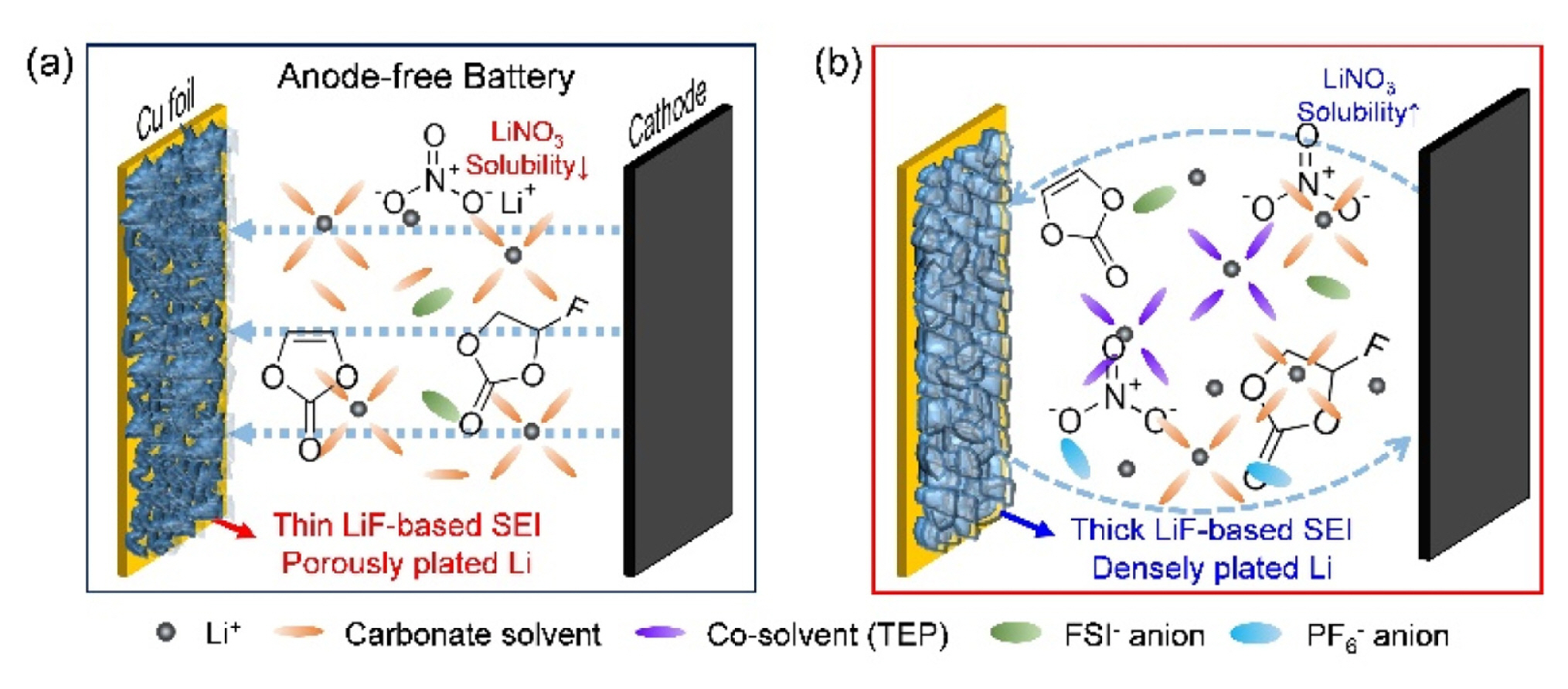
LiPF6 and LiFSI were used as salts in this study because both are stable salts for Li secondary batteries due to their good abilities for passivation and protection of the Al current collector, and low sensitivity to hydrolysis and high thermal/electrochemical stabilities, respectively [23–25]. The base electrolyte comprising of EC/EMC/DEC (3/5/2, v/v) with 5 wt% FEC and 2 wt% VC was chosen because it is one of the well-known carbonate electrolytes for LIBs and ether based solvent can suffer from severe oxidation over 4V (Fig. S1) [26–28]. The differences in the morphology of the deposited Li was attributed to the different reduction mechanisms on the Cu surface depending on the type of electrolyte (Fig. 3).
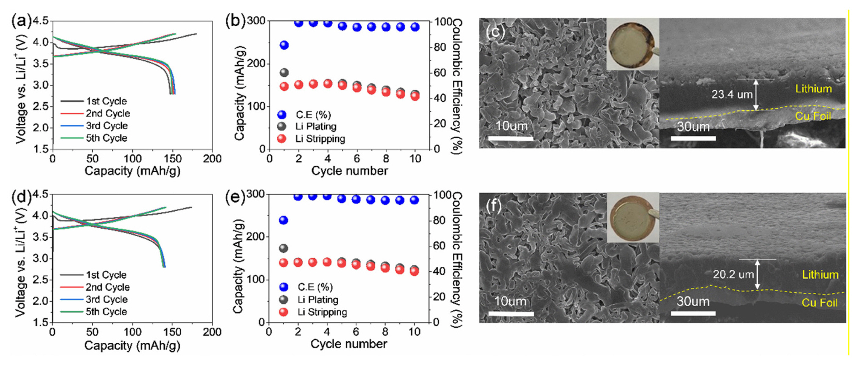
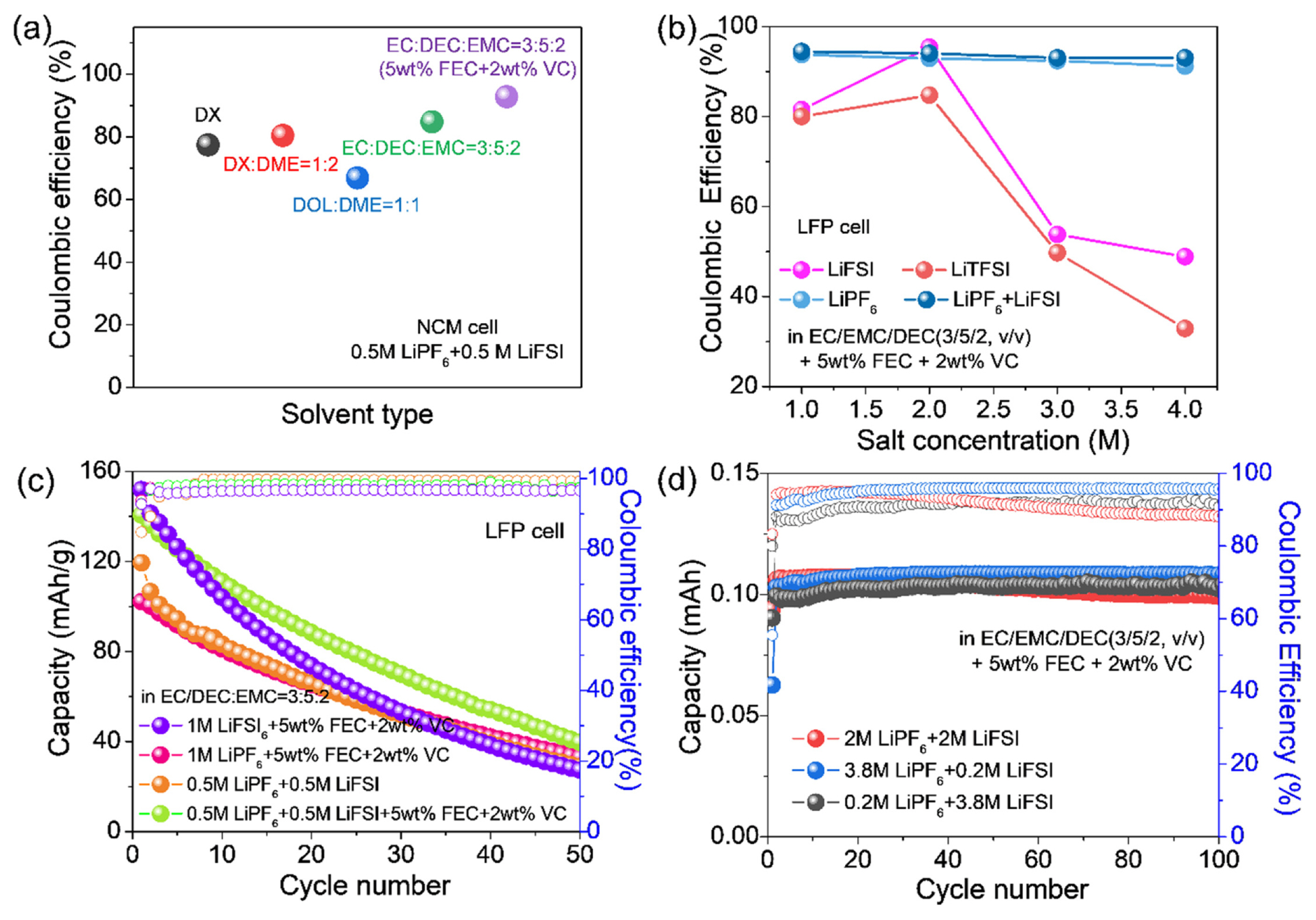
To identify the effect of each salt on the electrochemical performance, we evaluated the properties of LiFSI and LiPF6 by accessing NCM/Cu cell with EC/EMC/DEC (5:3:2, v:v) with 5 wt% FEC and 2 wt% VC carbonate based solvent (Fig. 4). The cell test was conducted in the voltage range of 2.8 – 4.2 V although slight FSI− induced corrosion can occur [29,30]. While the LiPF6 cell exhibited slightly lower discharge capacity potentially than that of LiFSI due to its lower ionic conductivity as will be discussed in the next Fig. 5, better capacity retention of 85.4% was achieved during 10 cycles compared to that of LiFSI case (84.3%). To unveil the reason for improved performance, SEM analysis was conducted to monitor the morphological difference of deposited Li under these two electrolytes (Fig. 4c and f). According to the top-view SEM images, a denser and more uniform deposited Li morphology was detected in the LiPF6 cell compared to the counterpart. Moreover, the cross-sectional SEM images showing thinner Li layer also verify more uniform Li deposition behavior under the LiPF6 based electrolyte than that of the LiFSI case, which causes the improved Li plating/stripping efficiency, supporting better cyclability of the LiPF6 cell. In addition, as the LiPF6 concentration increased, more uniform and denser Li morphology was observed, reconfirming the role of LiPF6 salt in the cell with carbonate solvent (Fig. S2).
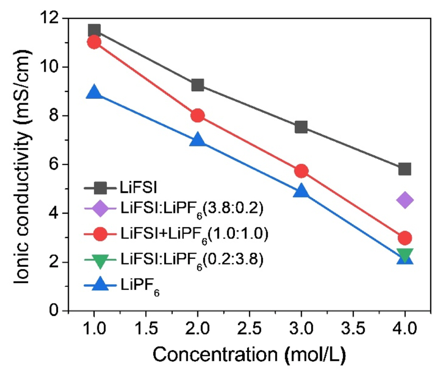
The variations in specific capacity and stability of the batteries with different salts, solvents, additives, and salt concentrations can be affected by ionic conductivities of the electrolytes (Fig. 5), and the conductivity values were summarized in Table S1. The ionic conductivity of a single-salt electrolyte widely fluctuates with the variation in salt concentration due to dependence of electrolyte viscosity, where the increase in viscosity with increasing salt concentration leads to a decrease in ionic conductivity. LiFSI exhibited a higher conductivity than LiPF6 at the same concentration level. Furthermore, the ionic conductivity of the dual-salt blended electrolyte followed the values between those of the two single salts. The conductivity of the blended-salt electrolyte decreased with increasing concentration, and a salt ratio of 1:1 led to a large drop in conductivity. However, the ionic conductivity increased as the blended ratio of LiFSI to LiPF6 increased, which seems to be due to the stronger interactions between the electrolyte solvents and LiFSI compared to LiPF6 [31–33].
The electrochemical properties of the NCM/Cu and LFP/Cu cells depending on the single- and dualsalt electrolytes, solvent types, and salt concentration are shown in Figs. 6a–c. The initial Coulombic efficiencies (ICE) of the different solvent combinations were measured during electrochemical testing. In general, ether electrolytes offer an electrochemical window with a relatively low upper limit, which has restricted their application in high-voltage batteries [32]. However, carbonate electrolytes, such as EC and DMC, are widely used in high-voltage batteries owing to their wide electrochemical windows [12–14,34–37]. Consequently, the commercial carbonate-based electrolyte cells exhibited better ICE at high voltage operation over 4 V compared to the ether based electrolyte due to ether solvent oxidation (Fig. 6a) [28]. The ICE was also evaluated upon the variation of salt concentration, which indicated that the salts containing LiPF6 offered higher ICE than the other salts, regardless of blending type and salt concentration (Fig. 6b). Nevertheless, LiFSI was chosen for this study owing to its lower sensitivity to hydrolysis and superior thermal/electrochemical stabilities [25,32,38]. Based on this, we investigated the effects of blended-salt electrolytes. The differences in cycling performance between the single and blended salts in the presence of additives were evaluated as additives can greatly affect electrochemical performance when mixed with the appropriate salts (Fig. 6c). Initially, the additive effect was accessed using FEC and VC for LiPF6 based electrolytes, where the best cycle performance was achieved using an electrolyte composition of 0.5 M LiPF6 + 0.5 M LiFSI with 5 wt% FEC and 2 wt% VC. Thus, it was found that the use of salt blending and appropriate additives can effectively enhance electrochemical performance. The effects of the concentration and ratio of blended salts in the EC/DEC/EMC (3:5:2) with 5 wt% FEC and 2 wt% VC were evaluated in the CE test using asymmetric Li/Cu cells. When the ratio of LiPF6/LiFSI was 0.2/3.8 (Fig. 6d), the best CE was achieved with an average CE of 97.3%, implying that the LiPF6 can more positively contribute to the CE than that of LiFSI in the carbonate solvent. However, despite applying the various electrolyte compositions, because the capacity fading of the full cells was still observed presumably due to LiFSI inactivation, we tried to activate LiFSI by adding LiNO3 to improve the cell performance. However, as previously reported, the application of LiNO3 in carbonate electrolytes is greatly restricted due to its low solubility [3,15,16]. Therefore, to improve the LiNO3 solubility, TEP was used as a co-solvent because it can moderately dissolve the LiNO3 even in the carbonate and TEP mixture [16]. The Tables 1 and S1 showed the decreased conductivity as the LiFSI or LiPF6 concentration increased, regardless of blending type, which was potentially attributed to the increase in salt concentration leading to increased ion pairing via ion association. In addition to this, the addition of LiNO3 mostly allowed for an increase in conductivity in the dual-salt carbonate electrolyte systems, enabling the improved electrochemical performance of the AFLMB.
The electrochemical properties of the dual-salt electrolyte cells were assessed and also compared to the cells with or without LiNO3 additive at various concentrations to understand the role of LiNO3 additive in the AFLMBs (Fig. 7). As mentioned above, LiNO3 is widely applied as an effective additive in ether-based electrolytes to increase the interfacial stability of Li-metal anode but it shows poor solubility in carbonate-based electrolyte [3,39]. Thus, in order to improve the LiNO3 solubility, we mixed a trace amount of TEP in the carbonate electrolyte, and dissolved the LiNO3 in the carbonate and ester mixed solvent.
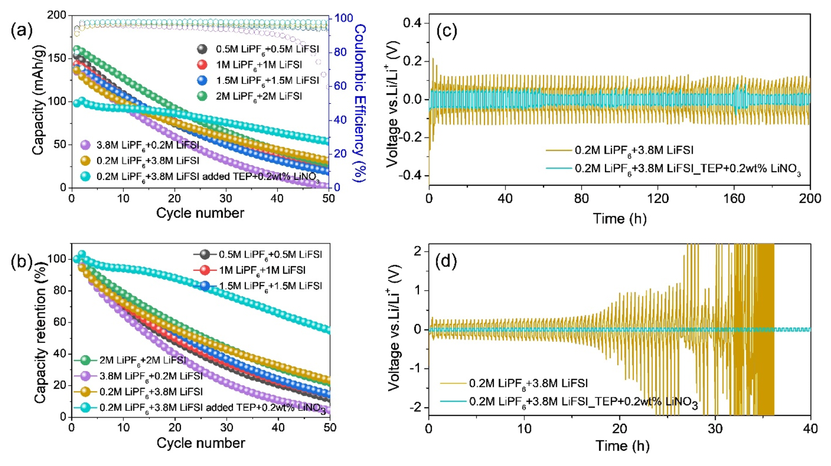
The cell with the dual-salt electrolyte exhibited IC fading of 162, 152 and 149 mAh/g as the salt concentrations increased up to 3 M, while the IC was enhanced to 170 mAh/g at 4 M cell. A mixed salt ratio of LiPF6/LiFSI > 1 led to poor capacity retention, where the 3.8 M LiPF6 + 0.2 M LiFSI electrolyte decreased up to ~ 4% of IC after 50 cycles (Fig. 7b). In contrast, the cell containing with the 0.2 M LiPF6 + 3.8 M LiFSI electrolyte (i.e., LiPF6/LiFSI < 1) exhibited relatively stable cycling performance. Additionally, relatively poor cycling performance (~23% capacity retention) was observed during 50 cycles in the cell based on the electrolyte composed of LiPF6 + LiFSI in EC/DEC/EMC (3:5:2) with 5 wt% FEC and 2 wt% VC without LiNO3, while the cell with LiNO3 exhibited stable cycling performance (~ 60% capacity retention) (Fig. 7b), although the initial capacity was decreased probably due the activation process caused by high viscosity from highly concentrated salts as well as thickly formed LiF-based SEI layer as will be discussed in detail in the next Fig. 8 and 9. This is strongly associated with the LiNO3 allowing for robust film formation and uniform Li deposition in the carbonate solvent-based electrolyte. To identify the morphology of deposited Li under the test condition with or without LiNO3, SEM characterization was carried out. Non-uniform dendritic Li deposition was observed in the cells without LiNO3 after the first Li plating (Fig. S3a~f), whereas a homogeneous and silverish Li deposition was observed when LiNO3 was added (Fig. S3g), which was attributed to the LiNO3 ability altering the deposited Li shape from dendritic to spherical [39].
The cycling stability and rate capability of the electrolytes containing LiNO3 were evaluated based on the Li plating/stripping cycling using the Li symmetric cells at different current densities of 0.5 and 1 mA/cm2 with fixed capacities of 0.5 and 1 mAh/cm2 (Figs. 7c and 7d). The cells with the 0.2 M LiPF6 + 3.8 M LiFSI in EC/DEC/EMC/TEP (1.5:2.5:1:5, v/v) with 5 wt% FEC, 2 wt% VC electrolyte and 2 wt% LiNO3 exhibited stable cycling at a low current and areal capacity 0.5 mA/cm2. However, the Li symmetric cell based on the same electrolyte without LiNO3 exhibited a significant overpotential under the same conditions, implying the interfacial instability of the Li metal anode. At a higher current density of 5 mA/cm2, obvious voltage fluctuations of up to ± 250 mV were detected during cycling for the cell without the LiNO3 additive, whereas the cells containing LiNO3 exhibited a lower polarization voltage of ± 30 mV. In particular, the lower overpotential of the Li symmetric cells with LiNO3 remained constant compared to the cell without LiNO3 for 200 h cycling at 1 mA/cm2. Furthermore, at a current density of 5 mA/cm2, the cell without LiNO3 exhibited a significant increase of overpotential after the initial 27 h of cycling. The failure of Li/Li symmetric cells is known to be strongly dependent on the Li plating/stripping efficiency [40]. Therefore, the superior cyclability of the cell with LiNO3 could be attributed to the development of robust interface in the initial cycle, the inhibition of dendritic Li-metal growth, and minimized electrolyte consumption.
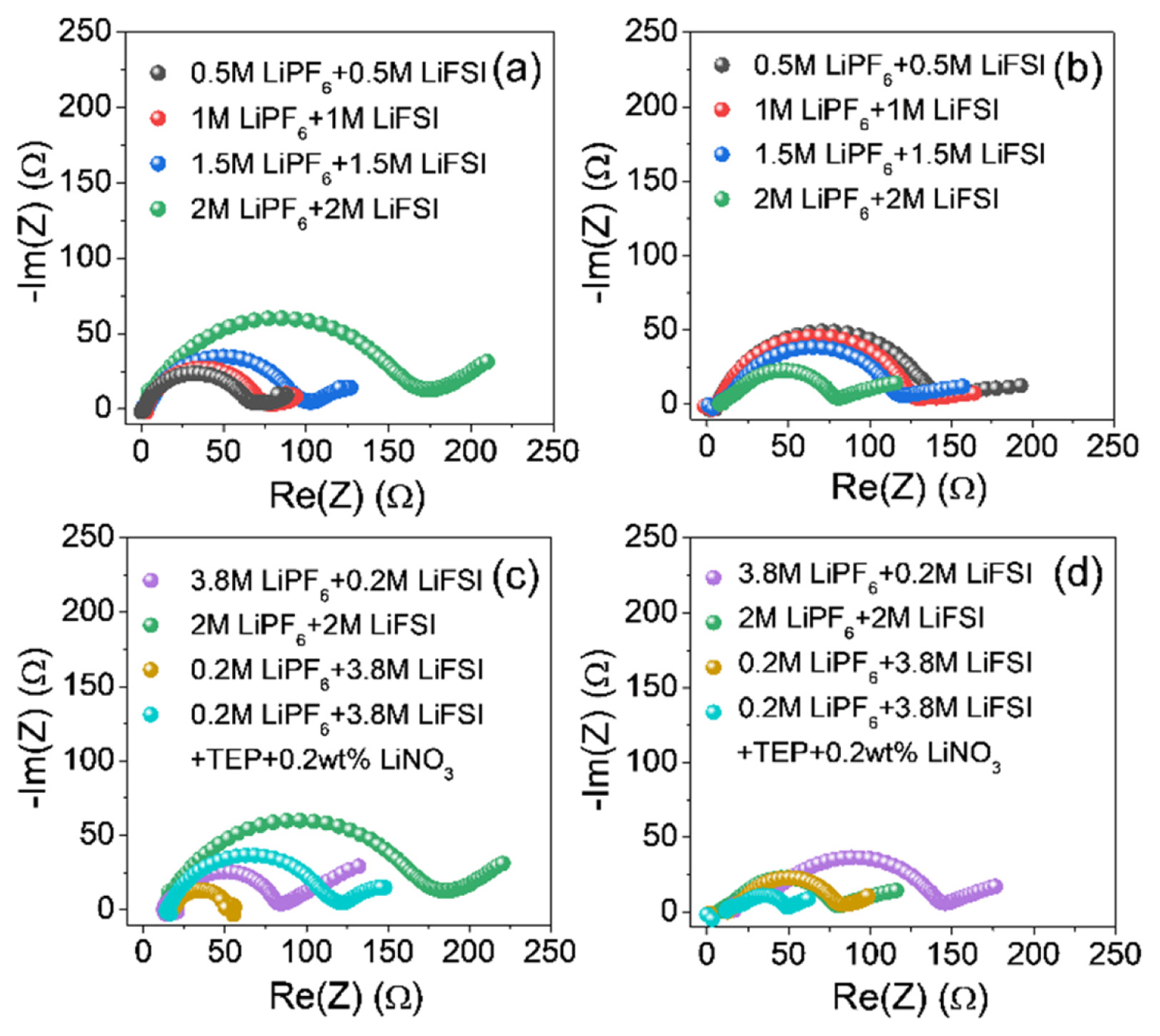
To identify the reason for stable cycling of LiNO3 containing cell, the EIS analysis was carried out. The Nyquist plots of the half cells with the seven blended electrolytes are presented in Fig. 8, where impedance measurements were taken after the first and 50th Li plating. The Nyquist plots of all electrodes during cycling exhibited a semicircular form with a sloping line, which are composed of ohmic resistance at the intersection with the horizontal axis at a frequency in the kHz region, the combined SEI layer and charge-transfer resistance in the high- to medium-frequency region, and the semi-infinite Warburg diffusion process in the low-frequency region [8,41–43]. The combined resistance of the SEI and charge transfer was characterized as the interfacial resistance (i.e., Ri = RSEI + Rct). A smaller Ri in an AFLMB system may be attributed to the uniform electrolyte/plated Li interface by a densely packed Li. Contrary to this, a high Ri value might result from the unstable SEI and dead Li formation during plating/stripping cycling, which can finally lead to poor cyclability by the depletion of active Li+ ions.
After the first Li plating, in the x M LiPF6 + y M LiFSI in EC/DEC/EMC (3:5:2, v/v) with 5 wt% FEC and 2 wt% VC electrolyte systems (x:y =1:1), the values of the semicircles associated with Ri for the cells with different total salt concentrations (i.e., LiPF6 + LiFSI) of 1, 2, 3, and 4 M were 60, 68, 74, and 170 Ω, respectively (Fig. 8a). These results are presumably ascribed to the viscosity increase of the electrolyte with increasing salt concentration, decreasing the ionic conductivity at the initial cycle (Fig. 5 and Table S1) [44]. However, after the 50th Li plating, it showed the opposite trend showing that the Ri decreased as the salt concentration increased (Fig. 8b). This behavior is due to the suppression of Li dendrite growth and stable SEI formation by the high concentration effect as previously reported (Figs. S2 and S3) [33]. In addition, the EIS analyses at high blended salt concentrations (total 4 M) were also conducted for the cells with the electrolytes of 3.8 M LiPF6 + 0.2 M LiFSI, 2M LiPF6 + 2 M LiFSI, and 0.2 M LiPF6 + 3.8 M LiFSI with or without LiNO3 in EC/DEC/EMC (3:5:2, v/v) with 5 wt% FEC and 2 wt% VC (Figs. 8c and 8d), and the cell with 0.2 M LiPF6 + 3.8 M LiFSI exhibited a smaller Ri than the others (3.8 M LiPF6 + 0.2 M LiFSI / 2M LiPF6 + 2 M LiFSI) owing to the increased LiFSI concentration allowing for faster Li+ ion movement compared to LiPF6 [33]. Apart from this, the effect of LiNO3 addition in the electrolyte was also depicted in the EIS results. In the case of the cell with LiNO3 salt, a somewhat higher Ri was observed than those of the cell without LiNO3 at the initial Li plating state, which indicates that the preformed SEI layer might be thicker in the presence of LiNO3 when compared to LiNO3-free electrolyte. However, it largely decreased to around 50 Ω and exhibited the lower resistance compared to those of controls after several Li plating/stripping cycles because of reduced resistance by activation process [45] as well as the advantages of the LiNO3 addition for controlling the Li deposition morphology and forming Li3N-based SEI layer [46], which is supported by SEM images of the electrodes after 1 and 50 cycles (Figs. S3 and S4). The electrodes of the cells without LiNO3 exhibited a dendritic and porous morphology due to the non-uniform deposition of Li during Li plating process. By contrast, in the presence of the LiNO3 additive, more evenly deposited Li with larger sized Li was observed compared to that of LiNO3-free case after repeated Li plating/stripping cycles. This outcome is consistent with the EIS result of the LiNO3-containing cell exhibiting the lowest resistance among the samples. A series of these consistent findings are in agreement with previous reports showing that LiNO3 can control the Li deposition shape and promote the formation of a highly Li+ ion conductive SEI [47].
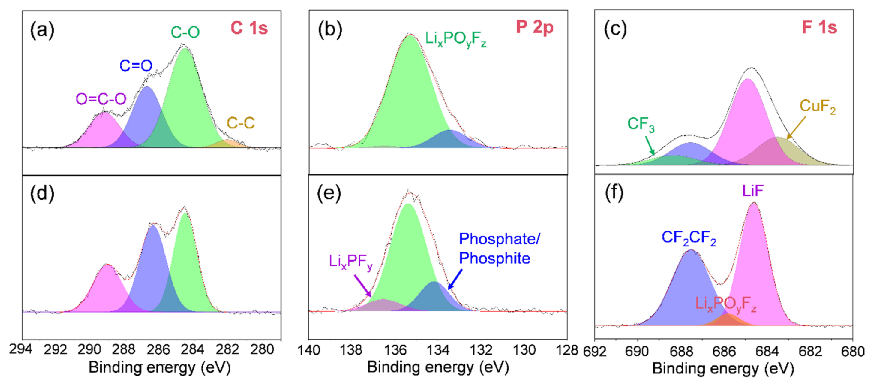
In order to identify the origin of the improved performance of LiNO3-containing cell, XPS analysis was conducted to characterize the chemical composition of the SEI layer formed on the Cu substrate in the EC/DEC/EMC/TEP-based electrolyte systems with or without LiNO3 (Fig. 9). The C1s XPS spectra of the electrodes of the Li/Cu asymmetric cells after the 50th Li stripping revealed that the similar organic products such as lithium carbonate, lithium alkoxides, lithium semi-carbonates, and organic polymers were detected on the both electrodes (Fig. 9a and 9d). Additionally, the P2p XPS spectra indicated that the SEI layer contained significant amounts of LiPF6 decomposition products such as LixPOyFz and Lix-PFy (Figs. 9b and 9e). Besides, the F1s XPS spectra revealed that the fluorine-containing chemical components in the SEI layer were mainly LiF, LixPOyFz, and LixPFy formed by the electrolyte decomposition (Figs. 9c and 9f). Also, the SEI layer on the Cu substrate in the electrolyte with LiNO3 exhibited a relatively high LiF content (685 eV) (Fig. 9f), and such LiF formation in the SEI layer was simultaneously accompanied by decrease in carbonaceous species (C–C, C–H, C–O, C=O, and etc). Therefore, it can be concluded that the highly concentrated FSI− anions and their high reductivity lead to the robust and ionic conductive LiF-enriched SEI formation especially in the highly concentrated electrolyte containing LiNO3. In addition to this, the FEC can be also sacrificed to form a LiF-based SEI layer, leading to the improved Li reversibility in the metallic Li-based anode due to less electron tunneling and inhibited SEI growth [48]. Accordingly, a series of these supportive analyses demonstrate that, through the formation of LiF-enriched SEI layer and the uniform Li deposition, the LiPF6 and LiFSI dual-salt based carbonate electrolyte with LiNO3 salt proposed in this study can conspicuously improve the cycling performance of AFLMBs.
4. Conclusion
In summary, for improving the cycle stability of the AFLMBs, unlike previous studies for ether-based electrolyte which is volatile and vulnerable to stability at high voltage, we proposed a high concentrated dual-salt carbonate-based electrolyte with appropriate additives. To identify the effect of the designed electrolyte, we analyzed the morphological difference of deposited Li and the chemical compositions of SEI layer in the various electrolytes. Due to the densely packed Li and LiF-based stable SEI layer, the electrolyte consisting of 0.2 M LiPF6 + 3.8 M LiFSI in EC/DEC/EMC/TEP (1.5:2.5:1:5) combined with 5 wt% FEC, 2 wt% VC, and 0.2 wt% LiNO3 exhibited improved capacity retention of 54.8% during 50 cycles and better Li reversibility compared to the controls with different salt ratios. In addition, we found that the LiNO3 played an important role for activating the LiFSI in the carbonate-based electrolyte. These finding provides an importance of electrolyte design for stable cycling of the AFLMBs. Moreover, the design rule of this study can be also applicable to other metal systems such as Zn, Al, Mg, and Na suffering from similar problems.