1. Introduction
Using solid electrolyte instead of traditional organic electrolyte to construct ASSLSBs can alleviate the shuttle effect in the process of charging and discharging [1ŌĆō3]. ASSLSBs due to their ultra-high theoretical capacity and energy density, as well as its high safety, environmental protection and low cost, have become the next generation of secondary energy storage battery with great development prospects [4ŌĆō6]. However, due to the poor physical contact (solid/solid) between the solid electrolyte and the electrode and the inherent insulation of sulfur, a large charge transfer impedance between the interface and a poor electron/ion transport in the cathode material are formed [7,8]. Generally, carbon materials with high conductivity, such as mesoporous carbon [9], porous graphene [10], carbon nanotubes [11] are used as host of active sulfur to improve the slow electron conduction in sulfur cathode. At the same time, the sulfur carbon composite material was blended with solid electrolyte with high ionic conductivity to prepare composite sulfur cathode (CPE), which can improve the problem of poor ion conduction of sulfur cathode [12,13]. Li7La3Zr2O12 [14] and Li10GeP2S12 [15] are common solid electrolytes, which can be used as active filler with polymer matrix (PEO) to prepare CPE to ensure high ionic conductivity, alleviate physical contact between electrolyte and electrode and reduce the interface impedance [16]. In order to solve the poor electron/ion conductivity of interface between cathode and solid electrolyte, CPE is an ideal choice for ASSLSBs. The CPE and conductive carbon materials play a synergistic role in improving the ion/electron conduction in the composite sulfur cathode, However, due to the poor electron conduction ability of CPE, the content of CPE in composite sulfur cathode will affect the electrochemical performance of ASSLSBs. It is urgent to determine the optimal electrolyte content to improve the reaction kinetics of the battery.
Zhang et al. [14] synthesized 7822gc solid electrolyte by mechanical ball milling method, and sulfur composite cathode was prepared according to the mass ratio of s-CNT:7822gc of 4:6. Due to the synergistic optimization of electron/ionic conductor, the constructed ASSLSBs showed extremely high theoretical capacity and cycling performance. At the current density of 0.1C, the discharge capacity of the first cycle reaches 1140.9 mAh gŌłÆ1. After 400 cycles at room temperature, the battery capacity retention rate is close to 100%. Han et al. [18] synthesized Li7P3S11 glass-ceramics solid electrolyte. The sulfurcarbon composite materials were prepared with BP2000 and S, and the composite S cathode was prepared according to the mass ratio of Li7P3S11: sulfurcarbon composite materials is 2:3. The capacity retention rate of the ASSLSBs was close to 100% at 4C after 1200 cycles. This is the best performance of ASSLSBs reported so far. It profits from the unique core-shell structure of BP2000 conductive carbon and the excellent ion/electron transport performance of composite sulfur cathode. Wang et al. [15] synthesized PEO-LiTFSI-BN composite solid electrolyte by using boron nitride (BN) as inorganic filler. The CPE slurry was used as binder, and the sulfur-carbon composite material was blended with the obtained composite solid electrolyte precursor slurry to prepare composite sulfur cathode. The electrode of the ASSLSBs had good physical contact with the composite electrolyte. After 100 cycles, the discharge capacity of the battery is 768 mAh gŌłÆ1 and the capacity retention rate is 83%. On the other hand, due to the light and soft characteristics of CPE and the close contact with the electrode, this kind of ASSLSB has strong designability and can be applied to intelligent wearable devices [16], and it has a wider application prospect.
In view of previous studies, the good ion/electron transport performance in sulfur cathode can be regarded as the key factor to improve the performance of ASSLSBs. In this work, in order to alleviate the poor electrode/electrolyte interface contact and improve the ionic conductivity of solid-state electrolyte, we first prepared PEO-LiTFSI-LLZO composite electrolyte, The anionic group at the end of the PEO molecular chain will combine with Li+ and drive the transport of lithium ions through the movement of the molecular chain. Adding LLZO can effectively reduce the crystallinity of PEO molecular chain, thus accelerating the movement of molecular chain and Li+ transport performance [17]. And then we selected rGO with high electronic conductivity as the electronic conductor and prepared S-rGO composites materials by melt diffusion method. And then, PEO-LLZO-LiTFSI composite polymer electrolyte was prepared, and used its slurry (CPEs) as an ionic conductor, mixing with S-rGO composites materials in different proportion to prepare the five kinds of S-rGO-CPEs composite cathode. The best content of CPEs in S cathode was obtained by comparing the electrochemical performance of the constructed ASSLSBs. This work has reference value for the research of lithium-sulfur battery with polymer electrolyte system.
2. Experimental
2.1 Preparation of S-rGO composite materials
S-rGO composites were prepared by conventional melt diffusion method. Sublimated sulfur (Sinopharm, analytical pure) and reduced graphene oxide (Nanjing Jicang nano Co., Ltd., 99.9%) were evenly mixed according to the mass ratio of 4:1, transferred to the reaction kettle, and then put into the oven at 155┬░C for 15 hours. After cooling, the S-rGO composite was obtained.
2.2 Preparation of PEO-LiTFSI-LLZO composite polymer electrolyte
Firstly, Ga-doped Li6.4Ga0.2La3Zr2O12 (hereinafter referred to as LLZO) ceramic powder was prepared by traditional solid state method. The specific experimental methods and properties can refer to our previous work[18]. Polyoxyethylene (PEO, Aladdin, Mw= 5 million) and lithium bis (trifluoromethane) sulfonamide (LiTFSI, 99%, Aladdin) were weighed according to the molar ratio (EO):(Li) of 18:1, then add the appropriate amount of acetonitrile (ACN, Aladdin, anhydrous class) magnetic stir for two hours, the uniform slurry was obtained, and then add LLZO powder with a mass fraction of 7.5%, after 24 hours of stirring, the solid composite electrolyte slurry (CPEs) was obtained. Take part of the slurry and add it to the PTFE mold (take 1.6ŌĆō1.8 mL for pouring each time), and then the solid composite electrolyte (the thickness of CPE is about 60ŌĆō80 ╬╝m) was obtained by vacuum drying at 45┬░C for 24 hours.
2.3 Preparation of composite sulfur cathode and battery assembly
The composite polymer electrolyte slurry (CPEs) was blended with S-rGO composite materials according to the mass ratio of 1:9, 2:8, 3:7, 4:6, 5:5, respectively. After 24 hours of magnetic stirring, the uniform composite cathode slurry was obtained. By controlling the height of the scraper, the mass loading of the composite sulfur cathode of all samples is about 1mg cmŌłÆ2. The obtained composite cathode slurry was coated on the aluminum foil with a scraper, vacuum drying at 60┬░C for 12 hours, after compaction and slicing, the cathode plate is obtained. Assemble batteries in the glove box according to the order of CR2025 type battery case (+), cathode plate, CPE, lithium plate, steel sheet, nickel foam mesh and CR2025 type battery case (ŌłÆ) sequence. After being sealed by button type battery packaging machine, it was moved to 45┬░C incubator for 12 hours to be tested.
2.4 Characterization methods
Field emission scanning electron microscopy (Quanta+FEG250) and X-ray diffraction (D8 advance) were used to characterize the morphology and phase of S-rGO composite materials. The CPE was sandwiched between two symmetrical steel sheets and assembled into a symmetrical sandwich structure (SS|CPE|SS) to measure impedance by electrochemical workstation (CHI604E). The electrochemical performance of ASSLSBs was tested by LAND battery-testing instrument (CT2001A).
3. Results and Discussion
3.1 Morphology and electrochemical performance of composite polymer electrolyte
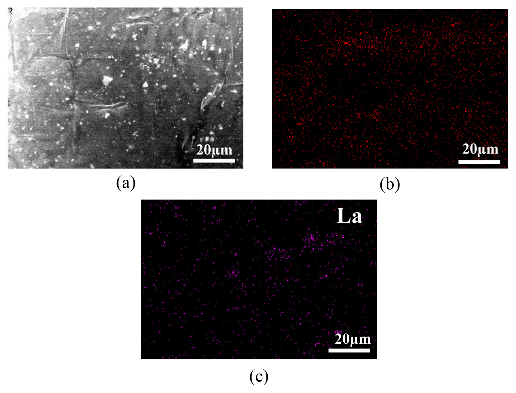
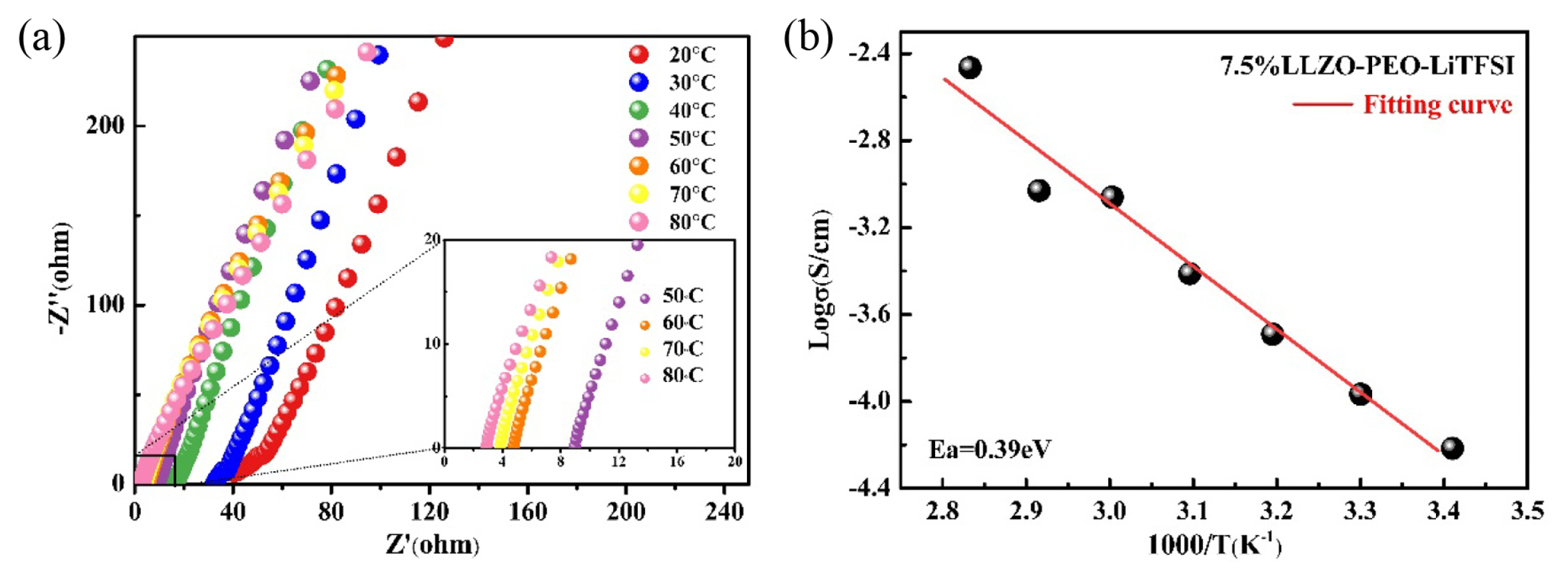
Fig. 1(a) is the SEM of the micromorphology of CPE, from which it can be observed that LLZO powder is dispersed in the PEO matrix. Fig. 1(b) and Fig. 1(c) are EDS diagrams of C element and La Element respectively, representing the distribution of PEO and LLZO respectively. LLZO was evenly distributed in PEO and was in good agreement with Fig. 1(a). Fig. 2(a) shows the EIS diagram of the prepared PEO-LiTFSI-LLZO electrolyte at different temperatures. It can be seen that with the increase of temperature, the impedance of the electrolyte decreases, which is because the increase of temperature is more conducive to the ion transfer. Two groups of data of 20┬░C and 60┬░C were selected to calculate the ionic conductivity of composite electrolyte by formula (3-1), they represent the low temperature and high temperature properties respectively (where L is the thickness of the CPE, S is the surface area of the CPE). The results showed that the ionic conductivity of PEO-LiTFSI-LLZO electrolyte was 1.16├Ś10ŌłÆ4 and 7.26├Ś10ŌłÆ4 S cmŌłÆ1 at 20┬░C and 60┬░C, respectively, which reached a high level [19]. The reason is that the addition of LLZO reduces the crystallinity of PEO molecular chain and improves the movement of PEO molecular chain, and Li+ can combine with anionic groups on PEO molecular chain, thus accelerating the conduction of Li+ [17]. Fig. 2(b) is the Arrhenius curve drawn according to the ionic conductivity of the CPE at various temperatures. After fitting, the activation energy of the composite electrolyte is calculated as 0.39 eV according to formula (3-2), which meets the operation requirements of lithium-sulfur battery (where, Kb and T represent the surface ion conductivity, Boltzmann constant and absolute temperature respectively).
3.2 Microstructure and morphology of S-rGO sulfur carbon composites
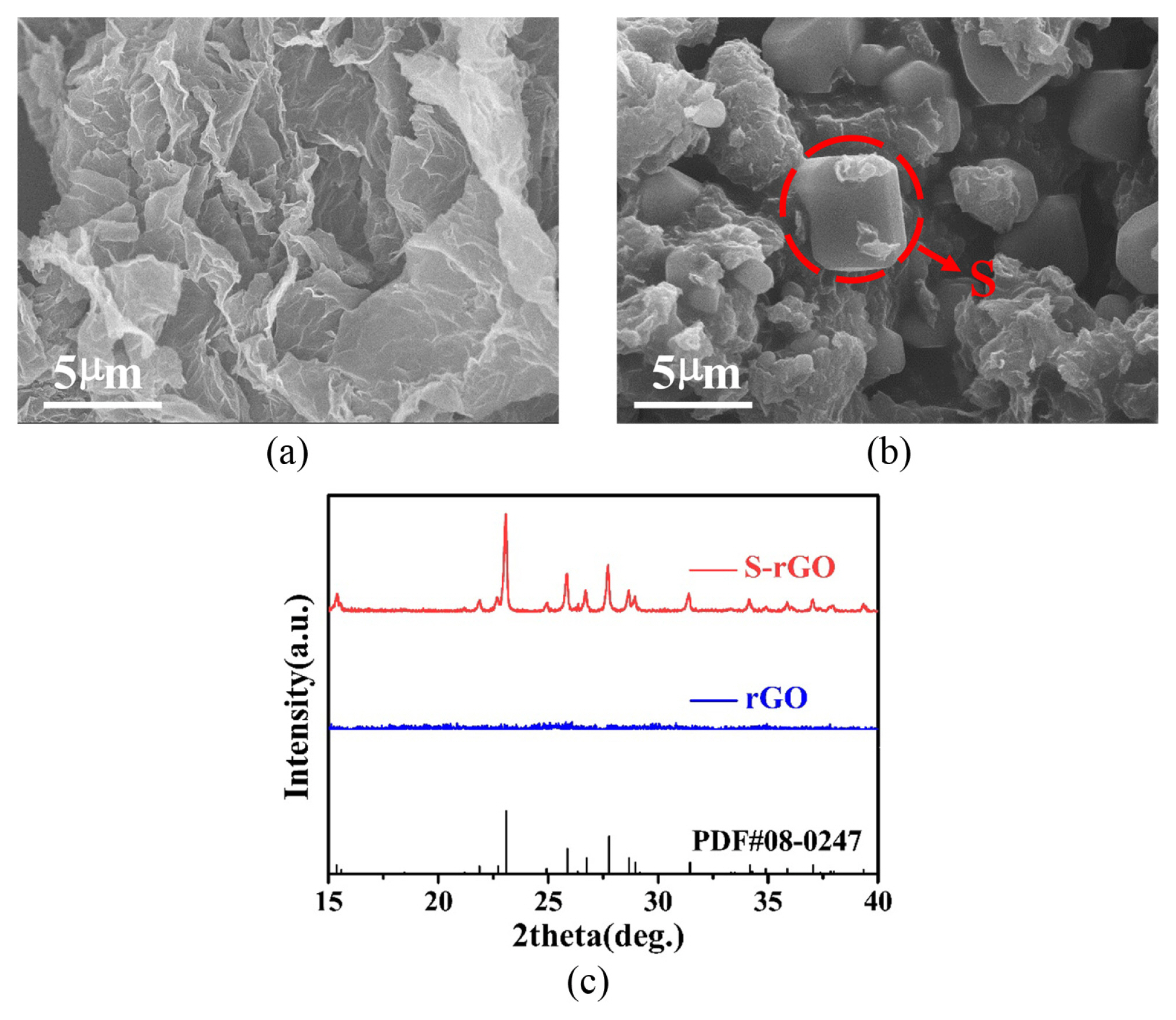
S-rGO composite materials were prepared by melt diffusion method. The SEM images of rGO and S-rGO were shown in Fig. 3(a) and Fig. 3(b) respectively. It can be seen from Fig. 3(a) that the rGO is sheet structure. After recombination with sulfur by melting diffusion method, sulfur particles can be obviously seen on the rGO (Fig. 2(b)), and rGO appears shrinkage phenomenon, this is caused by rGO contraction driven by the cooling process of molten sulfur. Part of the rGO is coated on the surface of S, which is conducive to electron conduction in the charging and discharging process. Fig. 3(c) shows the XRD diffraction patterns of rGO and S-rGO, rGO is amorphous, so there is no obvious diffraction peak, while S-rGO diffraction peak matches well with sulfur standard PDF card #08-0247, which further proves that S-rGO composite materials was successfully prepared.
3.3 electrochemical performance of ASSLSBs
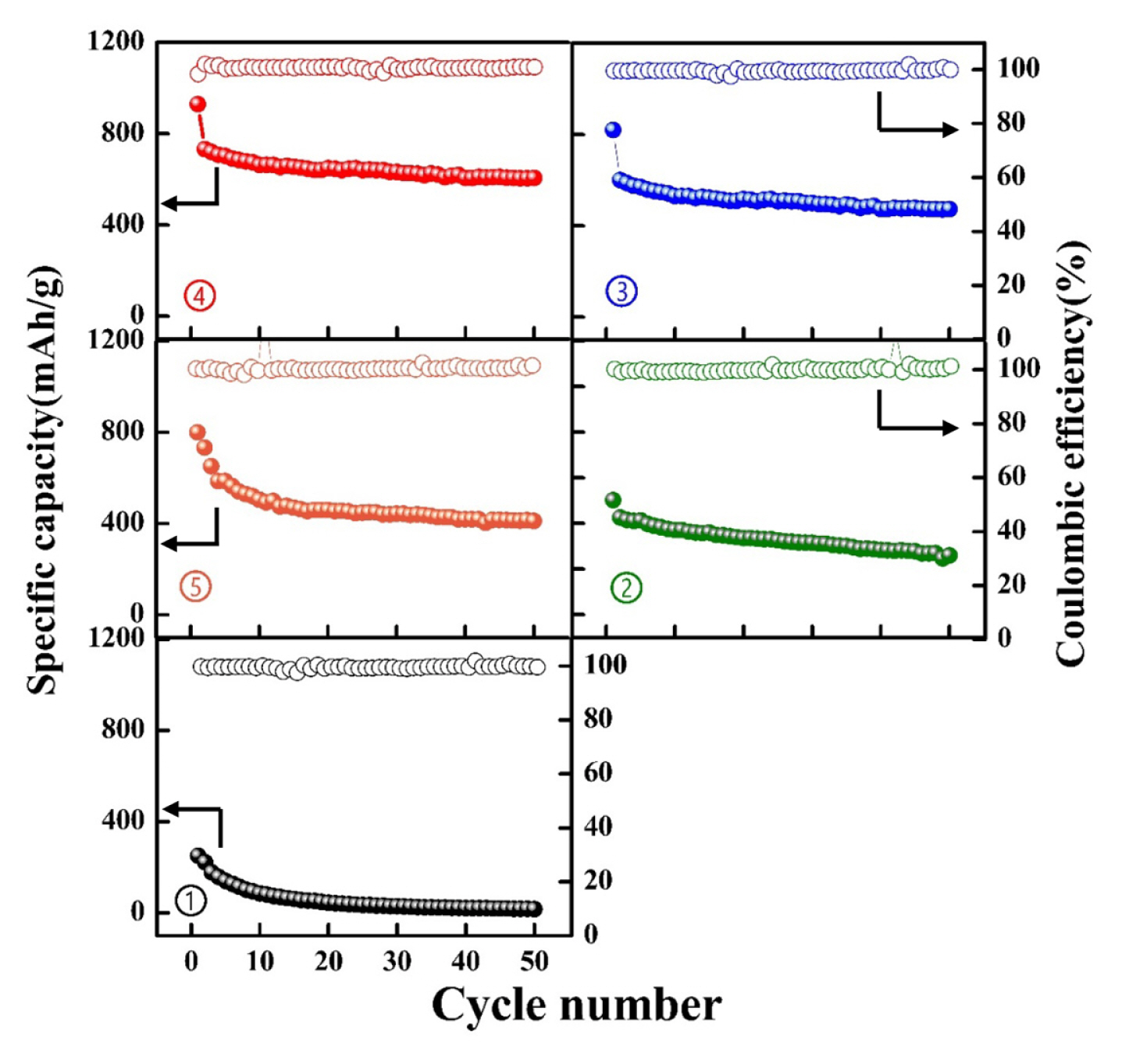
The composite sulfur cathode was prepared by blending CPEs and S-rGO composite materials with mass ratio of 1:9, 2:8, 3:7, 4:6 and 5:5. The samples were recorded as ŌæĀ, ŌæĪ, ŌÖé, ŌæŻ and Ōæż. The five samples were assembled into ASSLSBs under the same conditions, and their charge-discharge performance was tested (take 1C = 1675 mAh gŌłÆ1 as the standard, set the current density according to the actual mass loading of S cathode). Fig. 4 shows the first cycle charge-discharge curve of batteries constructed with these five samples at 0.2C (the actual current density is based on the load of S and its theoretical specific capacity), 45┬░C. Sample ŌæĀ is a composite sulfur cathode prepared with reference to the sulfur cathode binder content (10%) of liquid lithium-sulfur battery. It can be seen that the first cycle charge-discharge capacity is only 286 mAh gŌłÆ1, which is far from the theoretical specific capacity of active material sulfur (1675 mAh gŌłÆ1), this is due to the poor reaction kinetics caused by solid/solid contact in solid system, and the ions in cathode materials are difficult to transfer, which greatly reduces the utilization of sulfur. When the content of CPEs increased from 20% to 40%, the charge- discharge capacity of ASSLSBs increased from 512 mAh gŌłÆ1 of sample ŌæĪ to 923 mAh gŌłÆ1 of sample ŌæŻ, this is because with the increase of CPEs content, the ion transport performance of the cathode material also increases. The faster ion transport channel leads to the increase of the reactivity of sulfur, which shows a higher charge-discharge capacity. However, when the content of CPEs increased to 50%, the charge-discharge capacity of ASSLSBs constructed by sample Ōæż decreased to 810 mAh gŌłÆ1, which was due to CPEs was an electronic insulator, too much content will affect the electron transport performance of cathode. When CPEs content is 40%, rGO and CPEs have better synergistic transport of electrons and ions in the composite sulfur cathode, and the battery shows the best charge discharge capacity.
Fig. 5 shows the cycle performance diagram of ASSLSBs assembled by samples ŌæĀ to Ōæż at 0.2C and 45┬░C. The test results are consistent with the charge-discharge performance. Due to the low content of CPEs in sample ŌæĀ, the battery was difficult to operate after the 10th cycle. When the CPEs content is 40%, the battery can operate stably for 50 cycles, and the retention capacity is 653 mAh gŌłÆ1 after 50 cycles, the coulomb efficiency of each cycle is about 100%, it shows the best cycle stability. Therefore, for ASSLSBs with composite polymer electrolyte system, when the CPEs content in the cathode is controlled at 40%, the ion/electron synergistic transmission effect is the best, and the performance of the ASSLSBs constructed is the best. However, all batteries showed capacity attenuation in the first few cycles, which may be due to the contact failure between S and collector electrodes (coated with aluminum foil) caused by volume expansion of S, or the formation of a layer of insulating Li2S on the surface, resulting in the formation of ŌĆ£dead sulfurŌĆØ that does not participate in the reaction [20].
After the cycle, the battery was disassembled and the phase composition of CPE before and after the cycle was tested. The results are shown in Fig. 6. The characteristic peak of CPE matched well with the PDF card of standard cubic garnet results before the circulation, indicating that LLZO was successfully recombined [18], and the characteristic peak of LiTFSI could be obviously seen at 19┬░ and 23┬░, indicating that PEO-LiTFSI-LLZO composite electrolyte was successfully prepared. After the cycle, all the characteristic peaks were no obviously movement and no new substance was generated, indicating that the CPE had good compatibility with the electrode during the cycle, reflecting the good stability of PEO-LiTFSI-LLZO CPE.
4. Conclusions
In this work, PEO-LiTFSI-LLZO composite polymer electrolyte with high ionic conductivity was prepared. The ionic conductivity was 1.16├Ś10ŌłÆ4 and 7.26├Ś10ŌłÆ4 S cmŌłÆ1 at 20┬░C and 60┬░C, respectively, showing high ionic conductivity. In addition, high conductivity reduced graphene oxide (rGO) and composite polymer electrolyte slurry (CPEs) were selected to improve the electron/ion transport performance in the composite cathode, when the CPEs content is 40%, the constructed ASSLSBs shows the best charge-discharge performance and cycle performance. This work can be used as a reference for ASSLSBs constructed by composite polymer electrolyte.