1. Introduction
Hydrogen (H2) production by water (H2O) electrolysis is an important future energy source because of its carbon neutrality (H2O → H2 + 1/2 O2) [1–3]. To achieve this goal, which would ultimately aid in the commercialization of water electrolyzers, it is indispensable to develop electrocatalysts that exhibit high activity and physical/chemical stability toward the hydrogen evolution reaction (HER), while reducing the material and fabrication costs. Zn phosphating, which is widely used in the coating industry, has remarkable advantages in this regard; it involves the in situ growth of electrocatalytically active layers in a simple chemical bath at temperatures in the range of 50–80°C [4]. The nucleation and growth during Zn phosphating occur by balancing the corrosion of the metal substrate to increase the surface pH, resulting in the precipitation of Zn2+ and PO43−. Our previous reports suggest that the metal ions corroded from the substrate and the other ions in the chemical bath were also deposited in the film during the precipitation [5,6]. This allows elemental tunability of the catalytic layers for various target electrocatalytic reactions. Moreover, the direct growth of catalysts by phosphating renders the unhindered conductivity by polymeric binder, which is essential for the fabrication of electrodes with powdery catalysts [7].
Since the Sabatier principle and Trasatti volcano plot, which relate the chemisorptive bonding strength of intermediates in the rate-determining step and the overall heterogeneous electrocatalytic reactions, were reported [8], extensive efforts have been devoted to the development of cost-effective materials that can replace the Pt-group metals [9–11]. Based on the previous studies on the HER, noteworthy progress has been made with Ni-containing species such as intermetallic Ni–Mo catalysts, which show good electrocatalytic activity owing to the synergetic effects of Ni and Mo [12,13]. Ni–Mo catalysts can be prepared simply by electrodeposition on a conductive substrate [14,15]. Following the development of Ni–Mo catalysts fabricated by electrodeposition, substantial efforts have been dedicated toward the further improvement of their electrocatalytic activity and stability in the HER. One of the representative strategies is to adopt additional elements or phases. Recently, Cao et al. reported Ni–Mo–O derived Ni–Mo/MoO3–x electrocatalysts fabricated through hydrothermal reaction and annealing under a H2 atmosphere by varying the Had–alloy binding strength [16]. Eladgham et al. synthesized homogeneous and heterogeneous Ni–Mo–P nanoparticles via chemical routes and thermal treatment [17]. Chang et al. fabricated Ni–Mo/Cu nanosheets using chemical and electrochemical methods [18]. Although the previously developed Ni-Mo-based electrocatalysts show excellent performance in HER [16–18], there are still plenty of opportunities to further optimize the catalytic performance using simpler fabrication procedures with scalability.
In this paper, we report a simple method for the fabrication of Ni–Mo-based cathodes for water electrolyzers to produce renewable molecular H2 fuel using a Zn phosphating bath that was modified by the addition of MoO42−. The ZnNiMoPi film was directly grown on an Ni foam (NiF) by immersing the substrate in a Mo-modified Zn phosphating bath at 80°C for only 1 min. Thermal treatment in air was conducted for 2 h at 300°C to improve the physical stability of the deposited ZnNiMoPi on NiF (ZnNiMoPi/NiF). The electrocatalytic activity of ZnNiMoPi in the HER further increased after electrochemical activation, which was performed through 150 rounds of potential cycling in a 1.0 M KOH electrolyte. During the electrochemical activation, a large number of phosphate ions in the ZnNiMoPi f i lm were exchanged with hydroxide ions, resulting in a formation of ZnNiMoPOxHy with porous structures. The deposited ZnNiMoPOxHy showed remarkable electrocatalytic activity in the HER compared to bare NiF. Furthermore, a comparison of the HER performance of ZnNiPOxHy, which phosphatized without Mo4+, suggested that the Mo is the essential element for expressing better electrocatalytic activity in the HER. It is expected that the modified Zn phosphating is eligible for direct growth of catalytic layers on the conductive substrate, resulting in practically viable water electrolyzers for H2 production after further optimization of catalytic activities owing to its simplicity and scalability.
2. Experimental
2.1 Electrode preparation
Phosphating on NiF was conducted following a previously reported procedure with a slight modification. The NiF substrate was cleaned by sequentially immersing it in 0.2 M NaOH for 10 min and 1% HCl for 5 min at 80°C and room temperature, respectively. After washing thoroughly with deionized water (18.2 MΩ cm2), the catalytically active layers were simply deposited in a phosphating bath at 80 °C for a designated time. The phosphating bath comprised 10 mM aqueous Zn(NO3)2·6H2O and Na2MoO4·2H2O solutions containing 150 mM H3PO4, 30 mM HNO3, 0.5 mM NaF, 1.8 mM KNaC4H4O6·4H2O, and 25 mM KNO2. The pH of the bath was adjusted to 2.5 using 2.0 M NaOH. The deposited ZnNiMoPi/NiF was washed with deionized water and dried in an oven at 80°C. Following this, ZnNiMoPi was annealed by calcination at 300°C for 2 h. For converting ZnNiMoPi to ZnNiMoPOxHy, 150 rounds of consecutive potential cycling were conducted between 1.0 and 1.6 V vs. RHE (VRHE) to activate the surface for HER.
2.2 Electrochemical characterization
All electrochemical experiments were performed with a three-electrode configuration consisting of Hg/HgO (1.0 M KOH as filling solution, Pine Research Instrumentation) and carbon cloth as the reference and counter electrodes, respectively. To prepare the working electrode, NiF-based electrodes were cut into 1.0 cm × 1.5 cm. The electrochemical cells were home-built quartz cells, and the compartments of the counter electrode were separated by glass fritz. The electrolyte was 1.0 M KOH. To evaluate the HER performance, cyclic voltammograms (CVs) were acquired in a H2-saturated electrolyte using a potentiostat (VSP, BioLogic). Electrochemical impedance spectroscopy (EIS) was performed under a constant potential of −0.25 VRHE with 10 mV amplitude from 100 kHz to 100 mHz. Pt/C was prepared by drop casting ink, composed of commercial Pt/C powders (20 wt.%, Johnson Matthey) and Nafion ionomer (5 wt.%) dispersed in DMF, onto the surface of a glassy carbon rotating disk electrode (RDE) tip. The final Pt loading was 15 μg cm−2. The HER performance of Pt/C was evaluated using RDE assemblies (Pine Research Instrumentation) at 1600 rpm.
2.3 Physical characterization
Field emission scanning electron microscopy (FESEM) images were acquired using a SUPRA 55VP (Zeiss) instrument at an acceleration voltage of 2 kV at the National Instrumentation Center for Environmental Management of Seoul National University. XRD patterns were obtained on a SmartLab diffractometer (Rigaku) with a Cu X-ray source at the Yonsei Center for Research Facilities. XPS measurements were performed on a Kα X-ray photoelectron spectrometer with a monochromated Al source (Thermo Fisher Scientific).
3. Results and Discussion
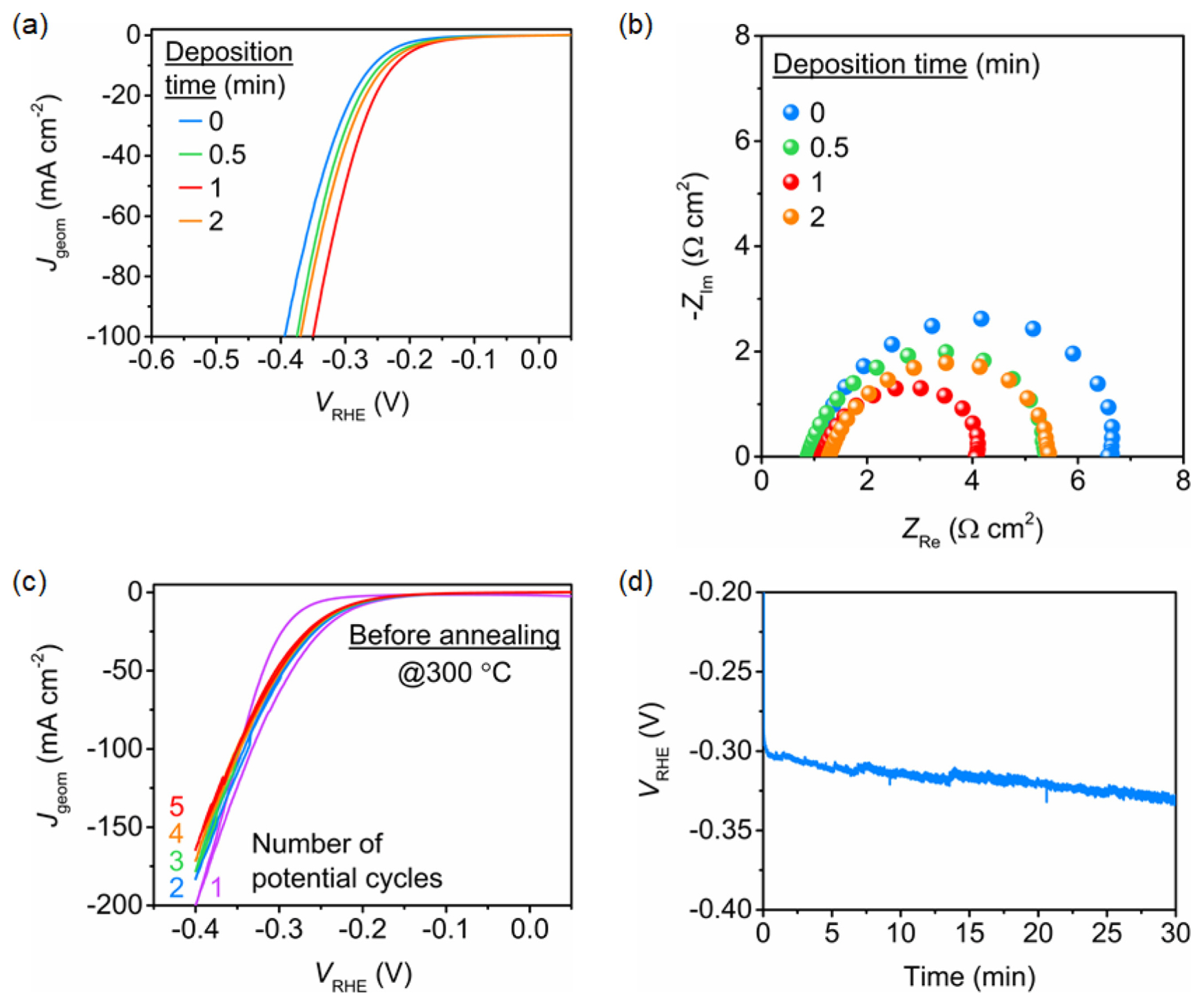
Linear sweep voltammograms (LSVs) were obtained after five potential cycles by varying the immersion duration in the phosphating bath to evaluate the electrode performance toward the HER. Fig. 1a shows the voltammograms of ZnNiMoPOxHy/NiF prepared by phosphating and electrochemical activation, but without annealing at 300°C. ZnNiMoPOxHy/NiF fabricated by 1 min of phosphating (red line) showed the best HER performance in H2-purged 1.0 M KOH. This was confirmed by EIS, studies, indicated that the ZnNiMoPOxHy/NiF phosphatized for 1 min (red dots) exhibited the smallest charge transfer resistance, as evident from the smallest diameter of the semicircle in the Nyquist plot (Fig. 1b). However, as shown in Fig. 1c, the current density steadily decreased during the first five potential cycles, which were performed to stabilize the catalytic surface. Moreover, the chronopotentiometric curve obtained at −50 mA cm−2 showed that the overpotential increased during the first 30 min of measurement, indicating poor stability (Fig. 1d). We assume that this instability originates from the physically weak adhesion of the catalytic layers formed due to phosphating.
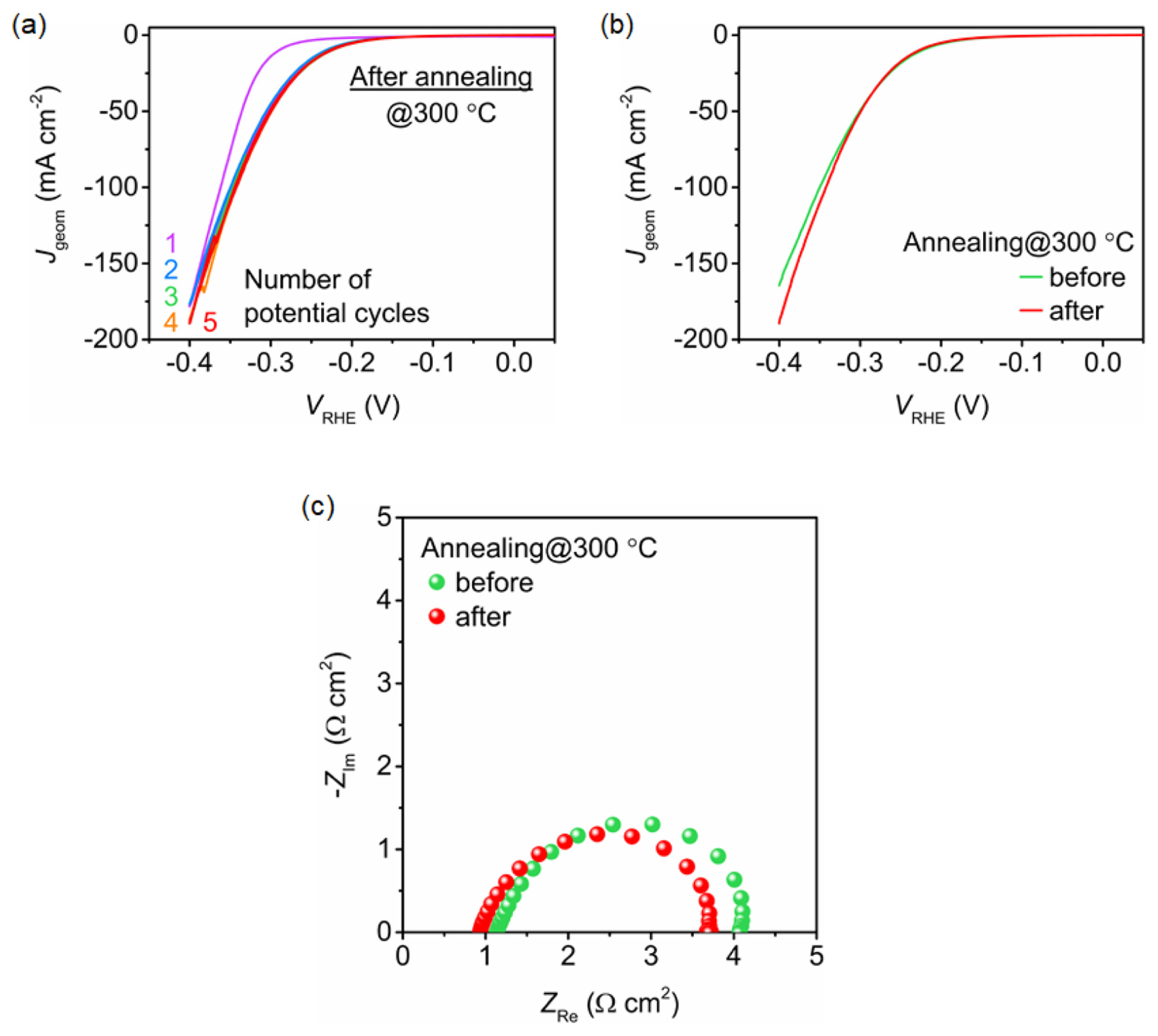
To improve the stability, the deposited ZnNiMoPi/NiF electrodes were subjected to heat treatment at 300°C for 2 h in air before electrochemical activation. The ZnNiMoPOxHy/NiF electrodes exposed to heat showed better electrochemical stability. As shown in Fig. 2a, the current density for the HER stabilized within the first five potential cycles. Unlike the electrodes without heat treatment, a stable current density (red line) for the thermally treated ZnNiMoPOxHy/NiF was observed at a current density that was slightly higher than the initial current density (purple line). The LSV curve of the heat-treated ZnNi-MoPOxHy/NiF indicated better HER performance compared to that without annealing, especially at an overpotential higher than 300 mV (Fig. 2b). However, the initial performance of the ZnNiMoPOxHy/NiF was poorer. According to the Nyquist plots, ZnNi-MoPOxHy/NiF shows a comparable charge transfer resistance (RCT) at of ~3 Ω cm2 at −0.25 VRHE, regardless of the thermal treatment. The RCT value was calculated by numerical fitting using a simple Randles equivalent circuit. Based on our observations, we postulate that the improved performance, which is observed only at current densities higher than 50 mA cm−2 after annealing, probably originates from the better physical adhesion of the catalytic layers and not from the chemical and/or structural changes.
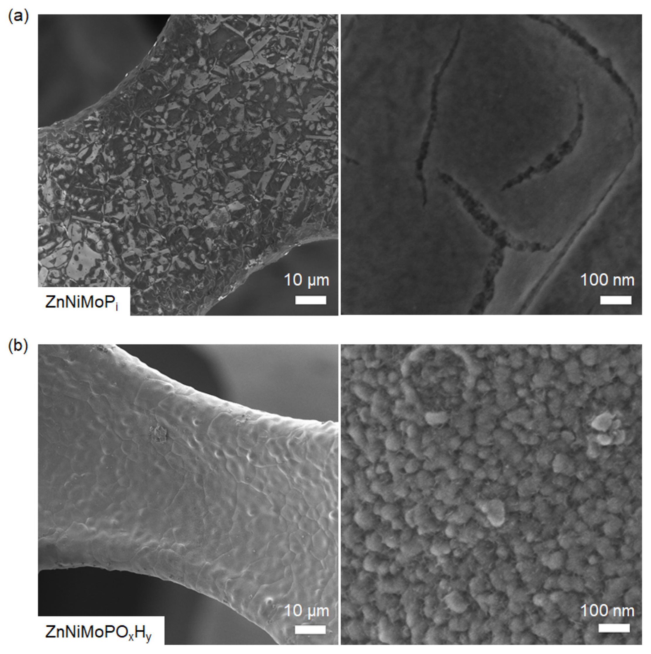
Fig. 3a and b show the FESEM images of ZnNiMoPi and ZnNiMoPOxHy on NiF, respectively. Upon heat treatment at 300°C, ZnNiMoPi exhibited a rough morphology with an inhomogeneous surface (Fig. 3a). Our previous reports suggest that the film deposited by Zn-based phosphating is composed of a crystalline mixture of phosphophyllite (Zn(M)(PO4)2·4H2O and hopeite (Zn3(PO4)2·4H2O), resulting in decreased uniformity, as indicated by the varying brightness in the FESEM images [5]. After electrochemical activation by 150 rounds of potential cycles in 1.0 M KOH (ZnNiMoPOxHy), the uniformity of the catalyst surface improved. Moreover, the higher brightness in the FESEM images implies better conductivity than that of ZnNiMoPi (Fig. 3b) [19]. At a higher magnification (Fig. 3b, right panel), a rougher surface comprising both particulates and small layered structures was observed.
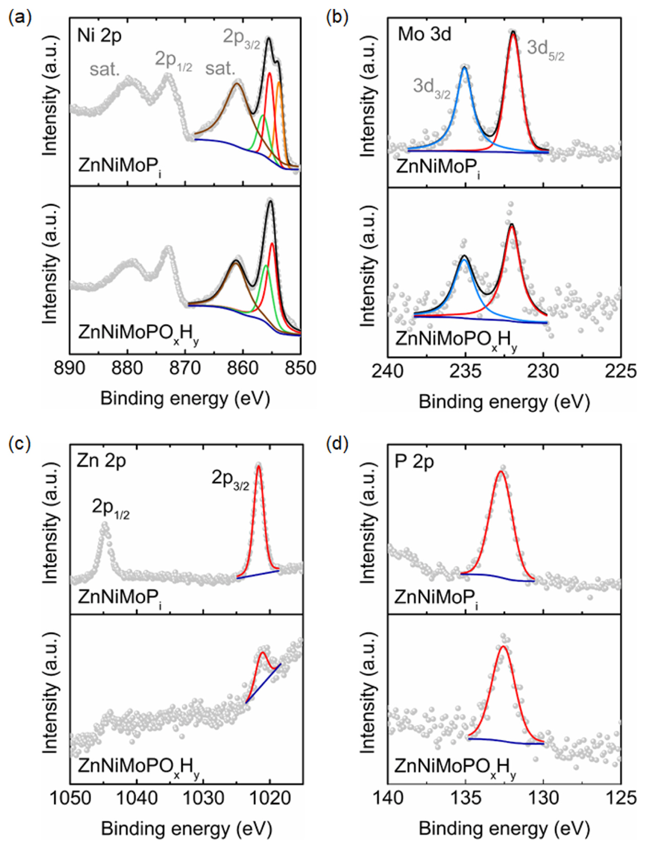
To investigate the elemental states of the surface catalytic layers, XPS analysis was conducted (Fig. 4). The overall shape of the Ni 2p spectrum of the phosphatized ZnNiMoPi is similar to that of NiO [20]. After thermal treatment and electrochemical activation, the shape of the Ni 2p spectrum of ZnNi-MoPOxHy was similar to that of a typical Ni 2p spectrum in Ni(OH)2 (Fig. 4a) [20]. In Fig. 4b, the peak positions of Mo 3d5/2 in ZnNiMoPi and ZnNi-MoPOxHy indicate a characteristic of Mo6+ [21]. The most prominent variation upon the post-treatment of ZnNiMoPi to form ZnNiMoPOxHy is seen in the Zn 2p spectra (Fig. 4c). The peak height of Zn 2p in ZnNiMoPi significantly decreased after the formation of ZnNiMoPOxHy, while the Zn 2p3/2 peak shifted toward negative binding energy from 1021.7 to 1021.2 eV. The reduced peak intensity after exposure to 1.0 M KOH electrolyte is in good agreement with that observed in our previous study, wherein the reduced peak intensity was attributed to the dissolution by forming [Zn(OH)4]2− [22]. However, the peak of P 2p spectrum at ~133 eV remained after the electrochemical activation, indicating the presence of residual phosphate groups in the catalytic layers of ZnNiMoPOxHy (Fig. 4d). As the exact chemical states of the catalysts surface related to the electrochemically active sites in the HER are not yet clear, further in-depth analysis and optimization of the HER performance using phosphatized Ni–Mo-based electrodes are underway in our laboratory.
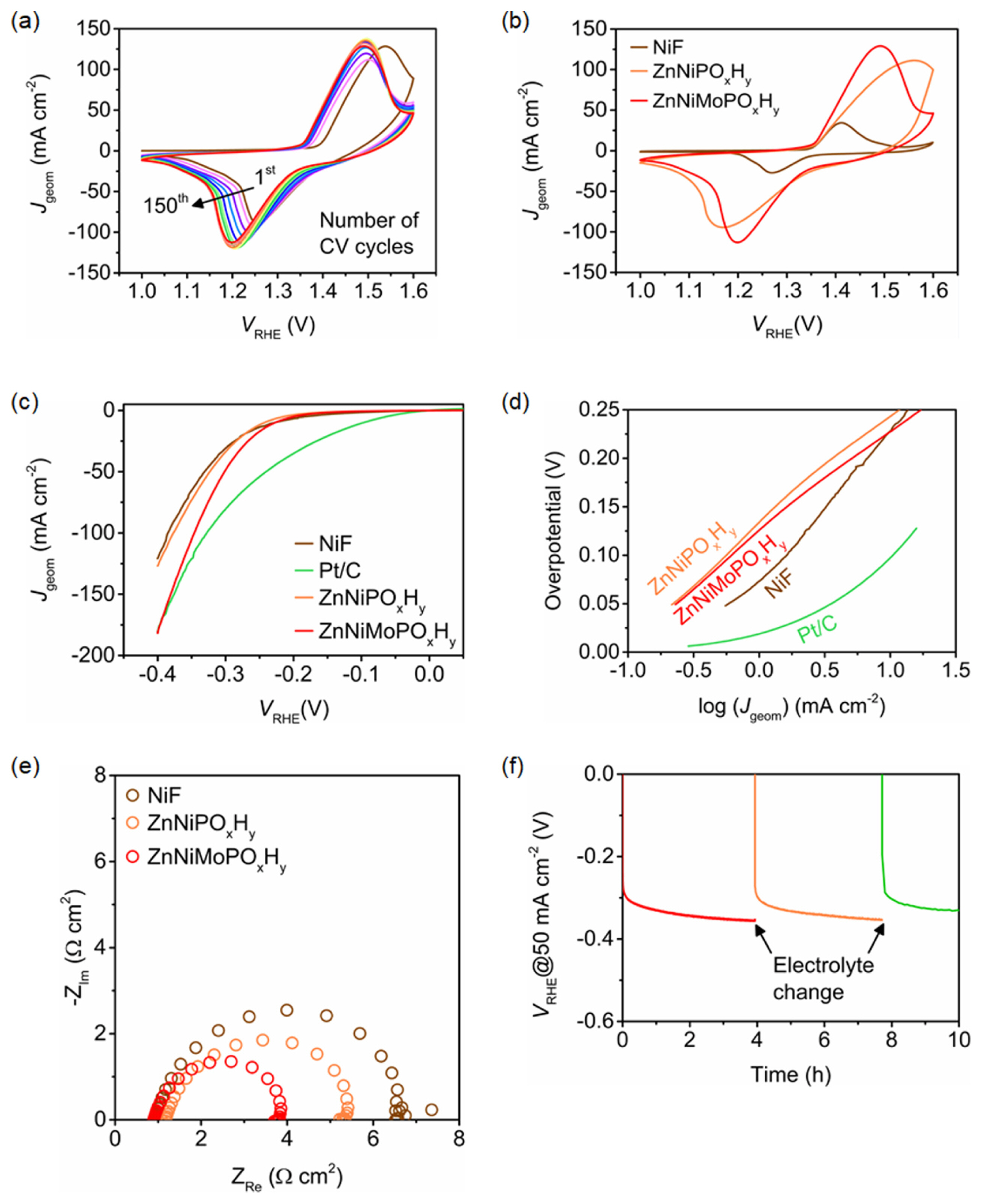
The electrochemical performance toward HER is shown in Fig. 5. Fig. 5a shows the CVs during the electrochemical activation for the conversion of heat-treated ZnNiMoPi into ZnNiMoPOxHy by 150 rounds of potential cycles in 1.0 M KOH. After the first CV, the redox peaks responsible for the electrochemical reaction Ni3+ + e− ↔ Ni2+ slightly increased with increasing number of potential sweeps, indicating an enlarged electrochemically active surface area (ECSA) [23]. The 150th CV curves of NiF, ZnNiPOxHy, and ZnNiMoPOxHy were recorded to compare the ECSA (Fig. 5b). ZnNiPOxHy was fabricated by the same procedure as that used to fabricate ZnNiMoPOxHy, but without Mo6+ in the phosphating bath. The ECSAs of ZnNiPOxHy and ZnNiMoPOxHy increased by 4.5 and 5.4 times, respectively, compared to that of NiF. The relative ECSAs were compared by integrating the peak area related to the reduction of Ni3+ ions (Ni3+ + e− → Ni2+), as shown in Fig 5b. The peak-to-peak separation corresponding to the Ni redox reaction (Ni3+ + e− ↔ Ni2+) was higher for ZnNiPOxHy (394 mV) than for NiF (142 mV). However, this peak-to-peak separation was slightly reduced when Mo was incorporated into the catalytic layers (293 mV). To evaluate the HER performance, the LSVs were acquired in H2-saturated 1.0 M KOH at 10 mV s−1 (Fig. 5c). Although commercial Pt/C shows the best HER performance (at overpotential < 350 mV), the ZnNiMoPOxHy/NiF electrodes exhibited reasonable activity at an overpotential of 346 mV for achieving a current density of 100 mA cm−2. Overpotentials of 386, 328, and 378 mV are required for 100 mA cm−2 in NiF, Pt/C, and ZnNiPOxHy, respectively. The remarkably better performance of ZnNiMoPOxHy than ZnNiPOxHy (without the incorporation of Mo) clearly revealed that elemental Mo is essential for achieving higher electrochemical activity in the HER. The LSV curve of ZnNiPOxHy was comparable to that of bare NiF, even though the ECSA of ZnNiPOxHy was higher than that of NiF. This also corroborates that Mo is the most important element for imparting a high HER activity to ZnNi-MoPOxHy. The Tafel slopes in the potential range between 50 and 75 mV of overpotential for NiF, ZnNiPOxHy, and ZnNiMoPOxHy were all ~120 mV dec−1, while the value for Pt/C was ~45 mV dec−1 (Fig. 5d). However, the Tafel plots clearly indicated that NiF had a higher geometric current density than ZnNiMoPOxHy at an overpotential < ~200 mV, revealing that the improved HER performance of ZnNiMoPOxHy compared to NiF at a relatively high current density predominantly resulted from the increased ECSA due to Mo-modified Zn phosphating of NiF, rather than the enhanced intrinsic electrocatalytic activity toward HER. Indeed, the current density of ZnNiMoPOxHy at −0.4 V increased by 1.5 times than the one of bare NiF, which is the lower extent than the increased ratio of ECSA in ZnNiMoPOxHy/NiF. According to the Nyquist plots, ZnNiMoPOxHy showed a smaller charge transfer resistance than NiF and ZnNiPOxHy, indicating a higher HER performance (Fig. 5e). As shown in Fig. 5f, the chronopotentiometric curve shows reasonable stability for ZnNiMoPOxHy at 50 mA cm−2. Although the potential corresponding to 50 mA cm−2 steadily retarded during the measurements, the performance slightly recovered after exchanging with a fresh 1.0 M KOH electrolyte. We shall verify the exact origin of this phenomenon by further investigation of the surface reconstruction under HER conditions.
4. Conclusions
We demonstrate the fabrication of cathodes for water electrolyzers by Mo-modified Zn phosphating. The ZnNiMoPi layer is grown on NiF by phosphating at 80°C for 1 min, followed by heat treatment at 300°C under air and subjecting to 150 rounds of potential cycling for electrochemical activation. Thermal annealing is required to improve the stability. During the activation in 1.0 M KOH, ZnNiMoPi converts into ZnNiMoPOxHy by the exchange of phosphates with hydroxides [5,6], while the ECSA increases by 5.4 times, compared to that of bare NiF. XPS analysis before and after the activation reveals that the chemical state of Ni is transformed into Ni(OH)2 from NiO, while the others, including Mo, Zn, and P, retain their qualitative states even after exposure to the KOH electrolyte in electrochemical environments. However, the peak intensity in the Zn 2p spectrum was largely reduced, indicating significant dissolution of Zn during activation. This might be the origin of the increased ECSA, while resulted in the formation of porous catalytic layers. The ZnNi-MoPOxHy/NiF electrodes require 346 mV of overpotential for achieving a current density of 100 mA cm−2 and good durability in the HER; this overpotential is lower than those required by bare NiF and ZnNiPOxHy/NiF. Tafel analysis indicates that the improved HER performance of ZnNiMoPOxHy/NiF compared to NiF might predominantly originate from the increased ECSA, although Mo is an essential element for the electrocatalytic activity toward HER, as suggested by the LSV curves and Nyquist plots. The phosphating method based on in situ growth of catalytic layers can be advantageous for water electrolyzers in terms of simplicity and scalability, although further optimization of the HER performance by variation of additional elements in the phosphating bath and detailed mechanistic studies on the electrochemical activation and the HER process are necessary.