1. Introduction
Unlike traditional sintering, where heat is transferred to objects by conduction, radiation and convection mechanisms, microwave irradiation (MI) provides rapid, economic, volumetric and uniform heating throughout the sample [1]. Since MI can achieve a higher heating rate and lower dwelling time at elevated temperatures, superior mechanical properties can be attained due to a lower tendency for coarsening and higher for sintering [2].
Indeed, the microwave coupling is conditioned by the existence of strong dielectric relaxations which can be excited by the microwave beam, relaxation due for an inorganic compound either to proton species (OH−, H2O, H3O+, etc.) or to conductive ions or at least locally mobile [3]. Eddy currents or magnetic induction play an essential role in heating high-conductivity materials such as metals [4]. The eddy currents induced in the conductor due to the interaction of the magnetic field produce a force that pushes the conducting electrons outward into a narrow area near the surface [5]. In the case of conductive powder compacts immersed in a relatively high-intensity electromagnetic field, other phenomena can occur, leading to a more pronounced and deeper heating of the conductive materials, like arcing and plasma formation [6]. Direct heating using MI in metals tends to be superficial; consequently, the practical usage would be limited to starting powders with a particle size in the order of skin depth [7]; for 2.45 GHz, this would be in the order of microns.
Most ceramics such as alumina and zirconia are poorly coupled with MI at low temperatures with 900 MHz and 2.45 GHz frequencies. This dependence varies greatly depending on temperature and increases rapidly with increasing temperature, making microwave heating extremely difficult to control for these types of materials [6]. Thus, ceramic microwave heating is mainly assisted by a susceptor, a material with a high dielectric loss at room temperature, that transmits heat to the part being sintered mainly by radiation [8]. Since the demonstration of the possibility of sintering ceramics by microwave heating by Berteaud and Badot in 1976 many works have been published without the technique being used other than for drying or melting [9].
Unlike structural applications that utilize MI to sinter thin films with a dense substrate such as implants or industrial cutting tools, the support often needs to be porous in an electrochemical cell such as a fuel cell to allow fuel and oxidant to pass through. Several attempts have been made to incorporate MI in ceramic electrochemical cells, including using MI to synthesize precursor powders for each cell component and fabricate a whole cell, with improvements in densification, conductivity and performance compared to traditional heating being reported. Wang et al. used a one-step co-firing with a SiC susceptor for a proton-conducting solid oxide fuel cell (SOFC) based on Barium Cerate with more than a 50% increase in performance over traditional heat treatment [10]. In another study, microwave heating resulted in finer particles near the anode interface but coarser near the cathode interface with overall improved performance resulting from the finer anode microstructure and the non-thermal effect of microwave sintering at the cathode [11]. Molero-Sanchez et al. used nitrate precursors and direct microwave heating to synthesize La0.3Ca0.7Fe0.7Cr0.3O3–δ and then used a susceptor to fabricate a half-cell [12]. In all of the electrochemical cell fabrication research, susceptor-assisted microwave heating was used, making it challenging to incorporate in practice.
To successfully sinter poorly coupled ceramics, finding a way to efficiently increase microwave absorption at low temperatures without producing local hot spots is essential. One way is adding a small fraction of electrically conducting powders to the specimen that can increase microwave absorption of the body [13]; moreover, the oxide layer, which can form on the metallic powders due to oxidation, can contribute further [14]. This technique has been used for zirconia with the addition of SiC whiskers to enhance microwave absorption [15].
Finding a way to conduct susceptor-less microwave heating can lead to several advantages; as microwave energy absorption is divided between the susceptors, insulation, and sample, it can be more energy-efficient [16]. It also shortens the processing time as the specimen directly absorbs and dissipates the heat. On top of that, the whole MI setup becomes simpler and cheaper to make.
In order to remove the need for susceptor, preserving the metallic state of the substrate could be the key to incorporating direct microwave heating. By doing that, the support act as a built-in susceptor at low temperatures and can uniformly heat the entire sample. As the temperature of the sample rises, direct coupling of MI and ceramic portion of the cell in support and electrolyte will follow. Since this process occurs in ambient air, the exothermic oxidation of the metal support and direct microwave absorption at elevated temperature provide the necessary energy to conduct the sintering process rapidly.
This study focuses on using direct microwave sintering on poorly microwave coupled ceramic without the use of any susceptor. To fabricate the electrochemical cell, Ni-YSZ cermet support is used as the substrate. YSZ was chosen as an electrolyte that has wide applications as a solid electrolyte yet poorly interacts with microwave below 600°C [17]; electrolyte was sintered directly on top of anode-support without the need of susceptor. Tubular geometry was chosen as it has better resistance toward thermal shock [18]. For better comparison to conventional electric furnace heating, MI only was used for the electrolyte sintering. To the best of the authors’ knowledge, this is the first report on the direct use of MI on a poorly microwave coupled oxide that is being used in electrochemical cell.
2. Experimental
2.1 Support fabrication
For the support, YSZ (Tosoh TZ-8Y) and NiO (Aldrich, <50 nm particle size) with a 35:65 weight ratio were mechanically milled for 24 h in an aqueous medium. 30 vol.% graphite (Sigma Aldrich <325 mesh) was added to the mixture. Slip casting in a plaster mold was used to fabricate the support which was pre-sintered at 1000°C for 3 h. In case of microwave sample, the cermet support was reduced in an electric tube furnace at 750°C for 3 h under a flow of 20 vol.% Hydrogen in Nitrogen.
2.2 Electrolyte coating
The coating slurry consisting of a mixture of as-received 8YSZ (Tosoh TZ-8Y), ethanol and binder (6 wt% ethyl cellulose in terpineol) was ball-milled for 24 h followed by ultrasonication to obtain a homogeneous suspension. Three rounds of dip coating were performed with 15 min intervals for drying at room temperature in ambient air.
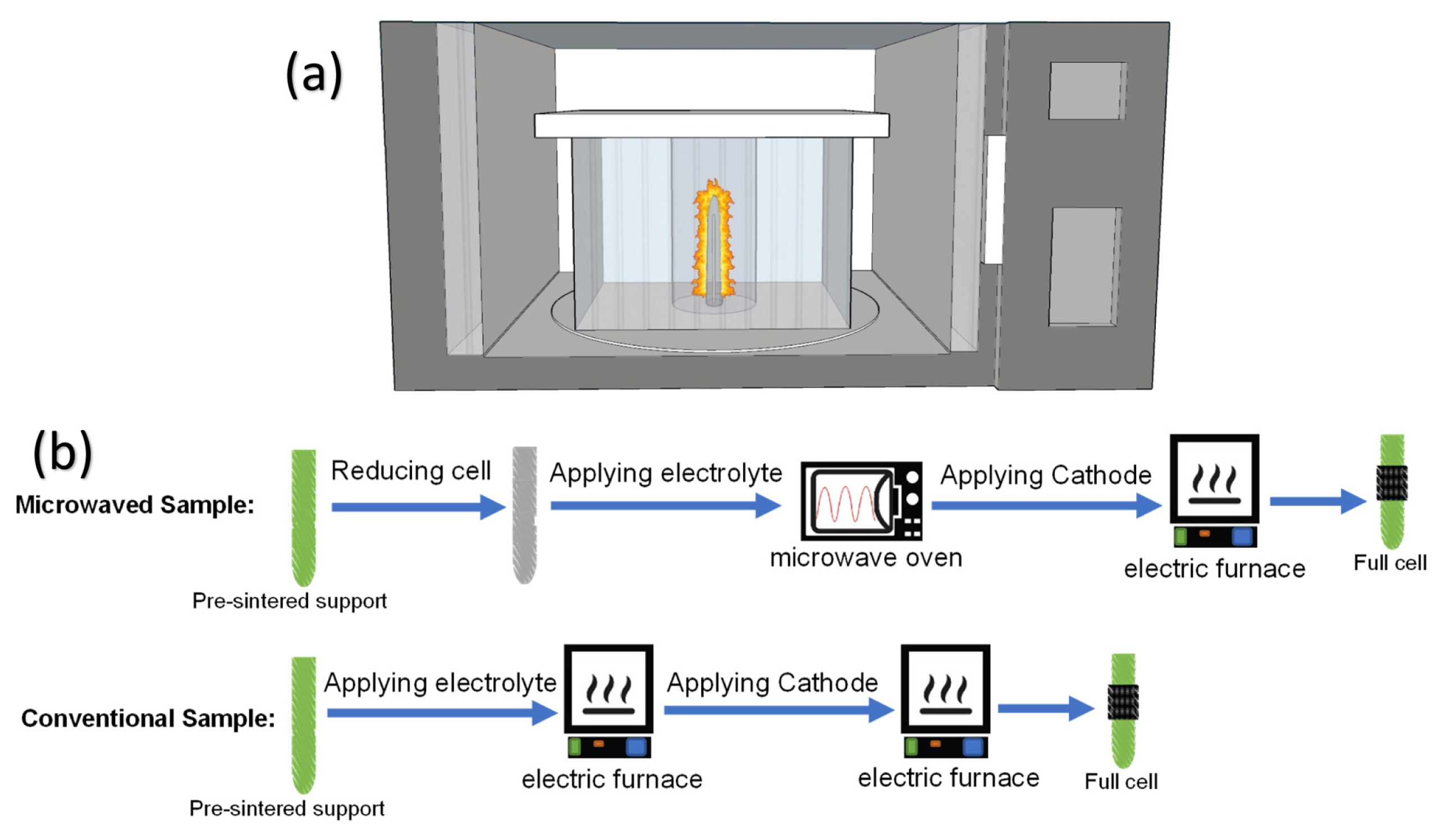
For microwave sintering, the microwave furnace used in this study was a modified household microwave oven (Panasonic NN-CD989S) shown schematically in Fig. 1(a). Power was supplied by a 1.1-kW continuously variable 2.45-GHz microwave generator with power settings manually controlled. The microwave cavity was surrounded by alumina fiber (C4501, Zircar Inc.) to prevent the magnetron and surroundings from heating up and from thermal shock. The sample was placed inside a three-piece custom-made cylindrical alumina fiber insulator to preserve the generated heat and prevent thermal shock. Zirconia felt (ZYF-100, Zircar Inc.) was used as the inner separator to prevent contamination. A type R thermocouple inside an alumina shell was placed underneath the sample to record the temperature. Methylene blue dye leakage tests were performed after microwave sintering to ensure leak-free electrolytes. For conventional sample, sintering was conducted at 1400°C for 3 h in the air using an electric furnace to have a leak-free electrolyte.
2.3 Full cell fabrication
A mixture of La0.6Sr0.4Co0.2Fe0.8O3 (LSCF, Fuel Cell Materials), azeotrope solvent, binder (polyvinyl butyral) and menhaden fish oil as the dispersant was used for the cathode ink. The resulting mixture was dip-coated on top of the electrolyte, then sintered at 800°C for 3 h. Gold paste and wires and copper mesh and wires were used for the cathode and anode lead connections, respectively. Fig. 2(b) shows the fabrication steps for both samples.
2.4 Electrochemical characterization
An electronic load and scanner (Agilent model N3301 and E4970A) measured the current-voltage curves. A Solartron 1255 frequency response analyzer and Solartron 1287 electrochemical interface were used for electrochemical impedance spectroscopy (EIS) measurements. The frequency range was between 0.01 Hz −1MHz, with 12 points per decade under open-circuit conditions. The data were recorded with 50°C intervals in a temperature range of 600–750°C using H2 + 3 vol.% H2O as fuel feed and air as the oxidant.
2.5 Microstructure characterization
The morphological features of fracture cross-section of cells were examined by scanning electron microscopy (Zeiss Sigma 300 field-emission scanning electron microscope). The relative density is calculated by bulk density divided by theoretical density. The open porosity of the sintered samples was measured by Archimedes’ method using water as the suspending fluid. The average of three sets of samples value was taken.
3. Results and Discussion
3.1 Microwave sintering
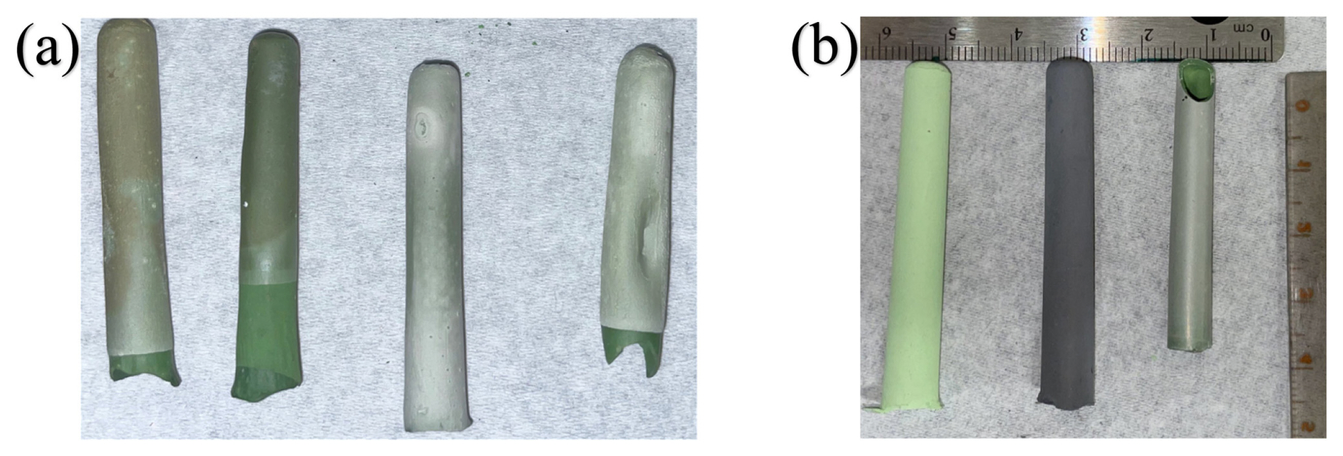
Several attempts with different MI powers and dwelling time were made to sinter a crack-free electrolyte. Some of the failed attempts can be seen in Fig. 2(a). These include local deformations and inconsistency in the support due to the formation of hotspots during sintering, which compromise cell integrity. During MI heating, inherent temperature gradients may result in severe temperature nonuniformities and cracking of processed materials [19]. Several adjustments on power rate, timing, sample position, holder and insulators were made. Janney et al. found that uniform heating is the key to preventing the local thermal hot spots [17]. Initially, the oven’s convection features pre-heated the inner chamber to 190°C. Although even at room temperature MI can be started, this will lower the thermal runaways for further steps. After 10 min, MI at 30% of power was applied for 10 min. Followed by 5 min, the power was set at 70% to maintain the reached temperature and conduct the sintering step and 5 min at 10% for the last step to mitigate thermal shock. Fig. 3 shows the temperature profile of the sample during sintering. Initially, it slowly started to increase. This part was due to the direct interaction of the metal portion in the support with MI; for Nickel, eddy current loss, hysteresis loss and residual loss contribute to heating [20]. Above 500°C, the exothermic reaction of Nickel oxidation also increases the heating rate [21]. Over 600°C, YSZ microwave coupling dramatically increases with the formation of intrinsic Schottky-type defects, leading to direct heating of the entire sample [22].
Fig. 2(b) shows the Ni-YSZ support before and after the electrolyte sintering using this method. In many instances, the top portion of cells cracked and separated during sintering as we suspect the top portion experienced the highest thermal shock and temperature gradient; yet this did not affect the integrity of the electrolyte. As the starting phase of nickel in the support was in oxide form and then reduced to nickel, we suspect the empty space due to this shrinkage provides enough space for the expansion of nickel to nickel oxide during microwave heating, and thus nickel inherently can have a negligible contribution to building up stress and cracking the sample. Final microwave cells had higher total shrinkage on average compare to conventional sample as listed in Table 1; Matsuda et al. found that shrinkage needs to be more than 20% to form a dense YSZ film using susceptor-assisted microwave sintering [23].
3.2 Electrochemical performance
Fig. 4(a) and (b) show the I–V and power density output curves of microwaved and conventional cells measured under air/H2 + 3 vol.% H2O. At lower temperature, the power performance of both cells is very comparable. At higher temperatures, conventional cells have slight advantage. At higher currents of microwaved samples, the end of the curves which result from concentration polarization and fuel starvation becomes more significant and deviate from ohmic behavior of conventional cell which resulted in lower performance for microwaved sample. OCV results of both cells are close to theoretical values based on the Nernst equation, suggesting a dense electrolyte prevents direct charge transfer or gas permeability and successful microwave sintering. OCV of the microwaved sample was slightly higher than the conventional sample, which might be due to better densification of the electrolyte, as reported in a similar study [24].
Fig. 4(c) shows the long-term run of the microwaved sample under the load for seven consecutive days. The voltage is kept constant at 0.7 V for this test, and the current is recorded over time. Some slight variations were observed mainly due to imperfect current collector attachment, especially at the anode side and coarsening of the electrode particles [25]. No excessive degradation in the performance was observed for microwaved sample.
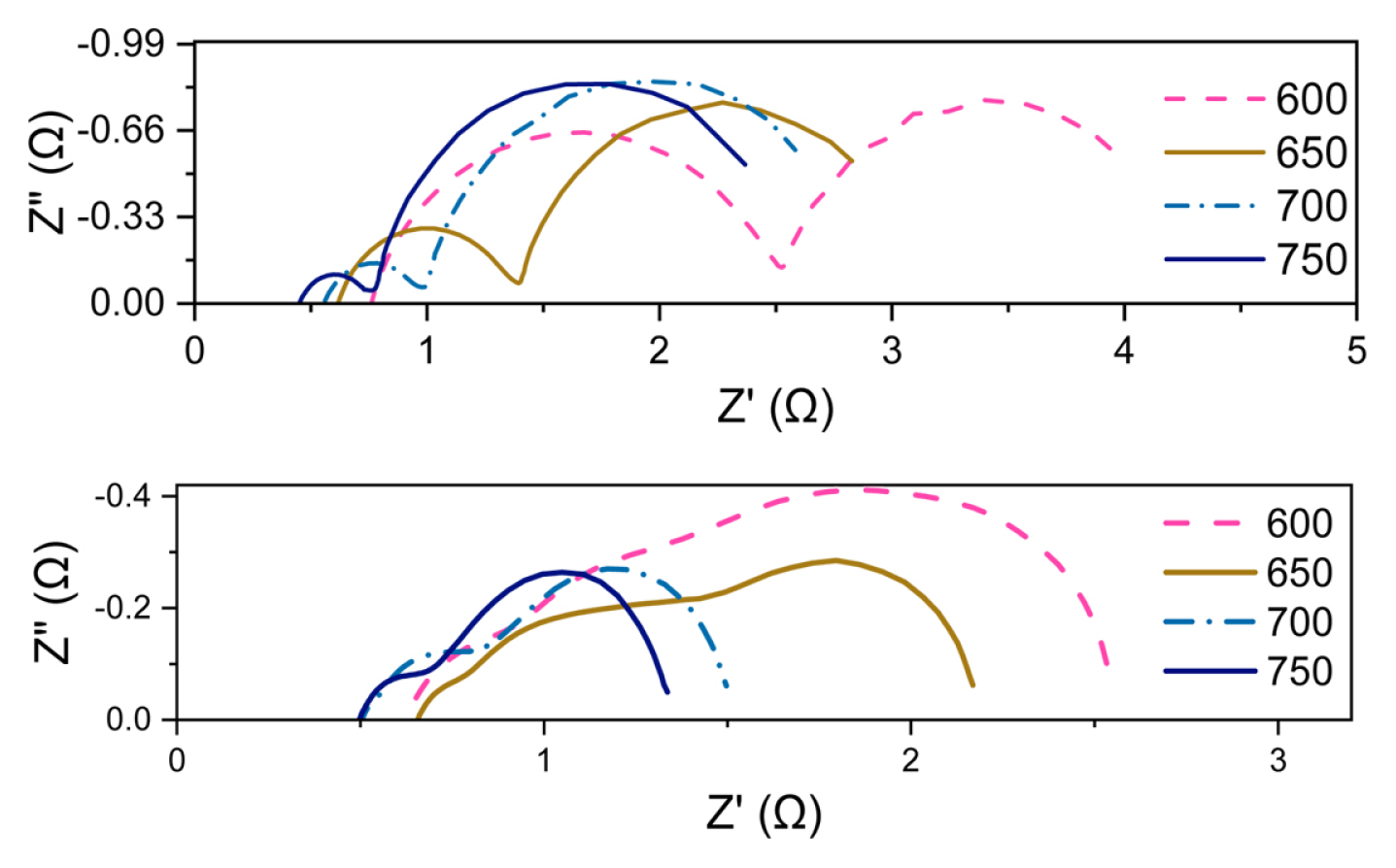
In Fig. 5, the far-right polarization that is temperature independent belongs to mass transfer occurring at the electrodes with ωmax = 8 Hz [26]. In agreement with I–V performance of both cells, concentration polarization of microwaved sample is relatively large compared to our conventional prepared cells with the same cathode. As the support experiences relatively, high temperatures compared to the electric furnace, it undergoes more rapid aggregation that reduces the overall porosity makes it more difficult for the fuel and steam to pass through. The ohmic part of the impedance correlates to the electrolyte and the connections. For microwaved sample it shows a slight improvement; we suspect this might be due to a better crystallization of electrolyte due to higher sintering temperature or it might be just slight variations in samples.
3.3 Cell microstructure
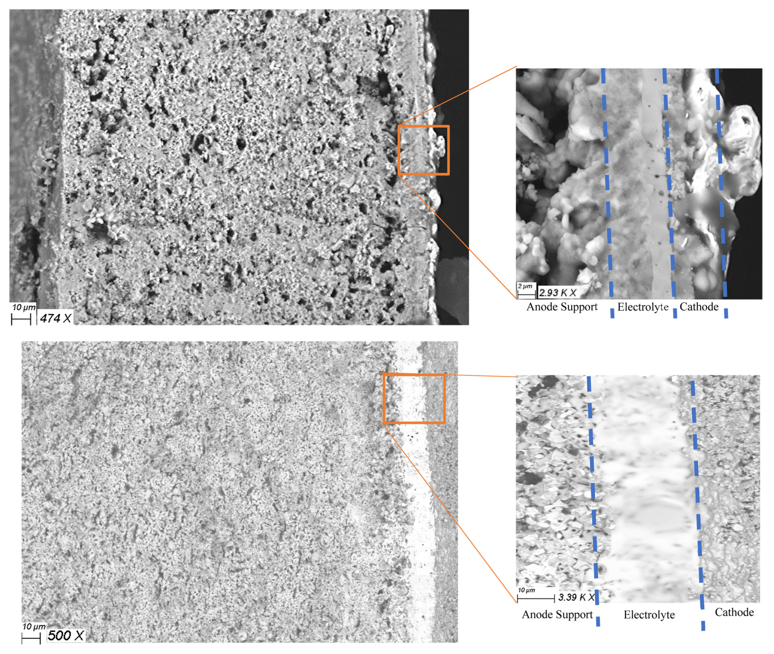
Fig. 6 shows the cross-section micrograph of both cells after electrochemical characterization. The distinctive longitudinal porosity which developed during conventional heating cannot be seen here. Instead, the support consisted of several big chunks with very little porosity inside and large vacancies around them. This swallowing behavior of MI to form a more prominent grain was also seen in an Al-SiC cermet [27]. These non-uniformities might be attributed to liquid phase formation during microwave sintering of Nickel powder [28].
The electrolyte region consisted of two unique features. The inner part (left side) consisted of almost melted particles of Nickel and YSZ sintered together, and the outer side (right side) forms a very dense layer with a small number of closed pores. The combination of exothermic oxidation of Nickel and microwave coupling can locally raise the temperature to melt Nickel, explaining this phenomenon [19]. Also, arcing and localized melting can occur as the local concentrations of electric field exceed the dielectric strength of the air inside [29].
Table 1 shows the measured open porosity of both microwaved and conventionally prepared supports. Raw porosity indicates the porosity after sintering and final is the open porosity after reducing the support to a cermet. The microwave sample shows lower porosity compared to the conventionally prepared sample. The microstructural findings are in line with the overall electrochemical behavior of the full cell with large concentration polarization bottleneck. This can be mitigated by additional optimization to preserve the open porosity during MI sintering, such as pre-coarsening the starting powder and increasing the pore-former content in the support. Since there is a limitation on the particle size of the metal to have non-superficial interaction with MI, this leaves the ceramic part of the support as the only viable part to be adjusted.
Geometry and composition uniformity of the support is essential to prevent thermal runaways. Extrusion would be a suitable method to maintain these properties for the substrate. In addition, with Nickel metal powder and YSZ as the starting powder of support, direct microwave sintering implementation can become much simpler and faster. The green body resulting from extrusion can be directly coated with ceramic electrolyte and sintered in one step in a microwave chamber with no pre-sintering or reduction necessary making it cheaper and faster compared to the conventional sintering process using an electric furnace. The cathode cannot be incorporated in this scheme as the high temperature of sintering process promote insulating phase formation such as lanthanium zirconate as the secondary phases, lowering the overall performance.
This study has some limitations. First is the lack of automation; for an ideal setup, a feedback loop system with direct temperature control of heating using thermometer and power regulation software of microwave output would be necessary, which enable a more precise sintering temperature and more uniform heating. The second limitation was using a household microwave oven. Although it provided a proof of concept, it was not optimized for high-temperature sintering; the non-uniform distribution of microwave irradiation, temperature and insulation were not perfect.
The lack of a susceptor in this process could make it ideal for practical applications as it would increase efficiency and decrease the processing time and the use of expensive setups. This process can easily be used for other similar devices that have (a) a portion of support that can be reduced to metal form and (b) poorly coupled coating material; heterogeneous catalysts, ceramic electrochemical cells and solid state batteries are some examples. Proton conductor oxides can be a great use case as they usually need higher sintering temperatures and thus expensive furnaces compared to Oxygen conductor counterparts; especially Barium Zirconate needs sintering temperatures exceeding 1600°C for a leak-free electrolyte [25]. Compared to previous results, we have a much simpler fabrication process that is faster and more cost-effective with a comparable power density [30].
4. Conclusions
In this study, we focused on a new method based on partial reduction of the substrate to enable the direct microwave sintering of a poorly coupled top layer without the need for any susceptor. The metal phase in the substrate can directly absorb the irradiation and increase the temperature of the whole sample, enabling direct microwave heating. The heat resulted in microwave interaction which along with substrate oxidation can then sinter the sample without a susceptor. The lack of a susceptor would increase the efficiency and decrease the complication of the system and processing time, making it ideal for practical applications. A solid oxide electrochemical cell was used as an example; YSZ electrolyte was coated on top of a Ni-YSZ support, and microwave sintering was used to sinter the half-cell. YSZ is poorly coupled with microwave irradiation, but we managed to sinter without any susceptor with this technique. The leakage test and full-cell power measurement results revealed a fully leak-free electrolyte. A similar sample using the conventional electric furnace was tested and compared.
The cell shows electrochemical performance comparable to traditional sintering techniques; some fuel starvation at high current was seen due to non-optimized microstructure of the support. Scanning electron microscopy was used to study the cross-section of the cell. It shows a distinct swallowed microstructure compared to the needle shape of conventional heat-treated samples. Density measurements also confirm lower open porosity of microwave prepared samples compared to traditional heating. In the end, we found this direct microwave irradiation technique very promising. Although the technique cannot be incorporated in all applications due to its requirements, it can be used extensively in heterogeneous catalysts and ceramic electrochemical cells such as solid oxide fuel cells and solid state batteries.