Corrosion Protection Performance of PVDF/PMMA-Blended Coatings by Electrochemical Impedance Method
Article information
Abstract
The effect of mixing ratio on the corrosion protection of carbon steel coated by a film composed of poly(vinylidene) fluoride (PVDF) and poly(methyl methacrylate) (PMMA) was examined using electrochemical impedance spectroscopy. Surface crystallization behavior and thermal properties of the PVDF/PMMA coated carbon steel were evaluated using polarized optical microscopy and differential scanning calorimetry, respectively. A Maltese cross-pattern spherulite crystal was observed in the PVDF/PMMA coating film, which became more apparent with increasing PVDF content. The highest corrosion protection performance was achieved with 60 wt.% PVDF-coated carbon steel, and delamination and corrosion reactions were observed for 20 wt.% PVDF-coated carbon steel. Further, corrosion protection performance with an amorphous/crystal mixture (PVDF/PMMA, 60/40 (w/w)) was better than those observed in the amorphous domain and the perfect-crystal domain of the PVDF/PMMA blended coating system.
1. Introduction
Organic coating materials are widely used to provide good appearance and protection from environmental corrosive agents like water, oxygen, and UV exposure. Numerous organic coatings, such as epoxy, urethane, and alkyd resins are used in industrial sites for various purposes. Poly(vinylidene fluoride) (PVDF) is high-performance coating material with semi-crystalline characteristics, which is commonly used in applications requiring excellent physical, chemical, and mechanical properties, including applications in outdoor environments [1]. Roll-to-roll coating application and spray methods are generally used to apply a PVDF coating to an underlying metal substrate and the coated substrate is baked at 200-250℃ to form a dry film. In industry, coating systems containing PVDF blended with acrylic polymers such as poly(methyl methacrylate) (PMMA) are applied, because of the good miscibility between such polymers and PVDF [2-6]. Coatings of blended PVDF and PMMA perform better than those using only PVDF, demonstrating good crack resistance and adhesion strength on metal substrates. During blending, PVDF and PMMA coatings are made miscible by melting them in a baking process at temperatures above 200℃. As the coating film cools, a PVDF crystal phase forms and coexists with an amorphous phase of PMMA. The crystal-to-amorphous ratio can be controlled by the PVDF-to-PMMA mixing ratio and the cooling speed of the blended coating film. Such a two-phase PVDF/PMMA coating affects its physical and mechanical properties, and provides improved flexibility and adhesion and reduced material cost compared to PVDF alone [7,8].
Many researchers have studied blended PVDF/PMMA coating systems, and have focused on crystal formation and their physical and chemical properties for different PVDF/PMMA mixing ratios [9-12]. As discussed above, PVDF/PMMA blended coatings are desirable materials for various applications. Nevertheless, the corrosion protection performance of PVDF/PMMA coatings and the effects of the PVDF/ PMMA mixing ratio and crystallinity on corrosion protection performance have rarely been reported.
The objective of this study is to examine the effects of the PVDF/PMMA mixing ratio on the corrosion protectiveness of PVDF/PMMA-coated carbon steel using electrochemical impedance spectroscopy analysis [13-15].
2. Experimental
2.1 Materials and preparation of PVDF/PMMA-blended coating
PVDF (HYLAR 5000, Solvay, Belgium, Mw: 600,000-700,000) and PMMA (PARALOID B-44, Dow Chemical, USA, Mw: 140,000) were used as coating materials, and glycol ester (supplied by Aldrich, USA) was used as a solvent. The blended PVDF/PMMA solution was prepared in various mixing ratios as listed in Table 1. To prepare the PVDF/PMMA coating films, PMMA solutions of different concentrations were added to the PVDF solutions. Then, the combined PVDF/PMMA solution was stirred vigorously by a mechanical homogenizer for 1 h and degassed for 10 min using sonication. After degassing, the PVDF/PMMA coating films were prepared via solution casting, using a bar coater on a carbon steel plate for the corrosion tests, and on a Teflon plate for microscopic observation and thermal analysis. To support better coating adhesion, the carbon steel surface was blasted with steel-grit resulting in an average surface roughness of 2.0 μm. The coated specimens were placed in a convection oven at 200℃ for 1 h. The PVDF/PMMA-coated carbon steel and Teflon plate were then removed from the convection oven and air-cooled to room temperature. The PVDF/PMMA coating films were removed from the Teflon plate for microscopic observation and thermal analysis of the samples.
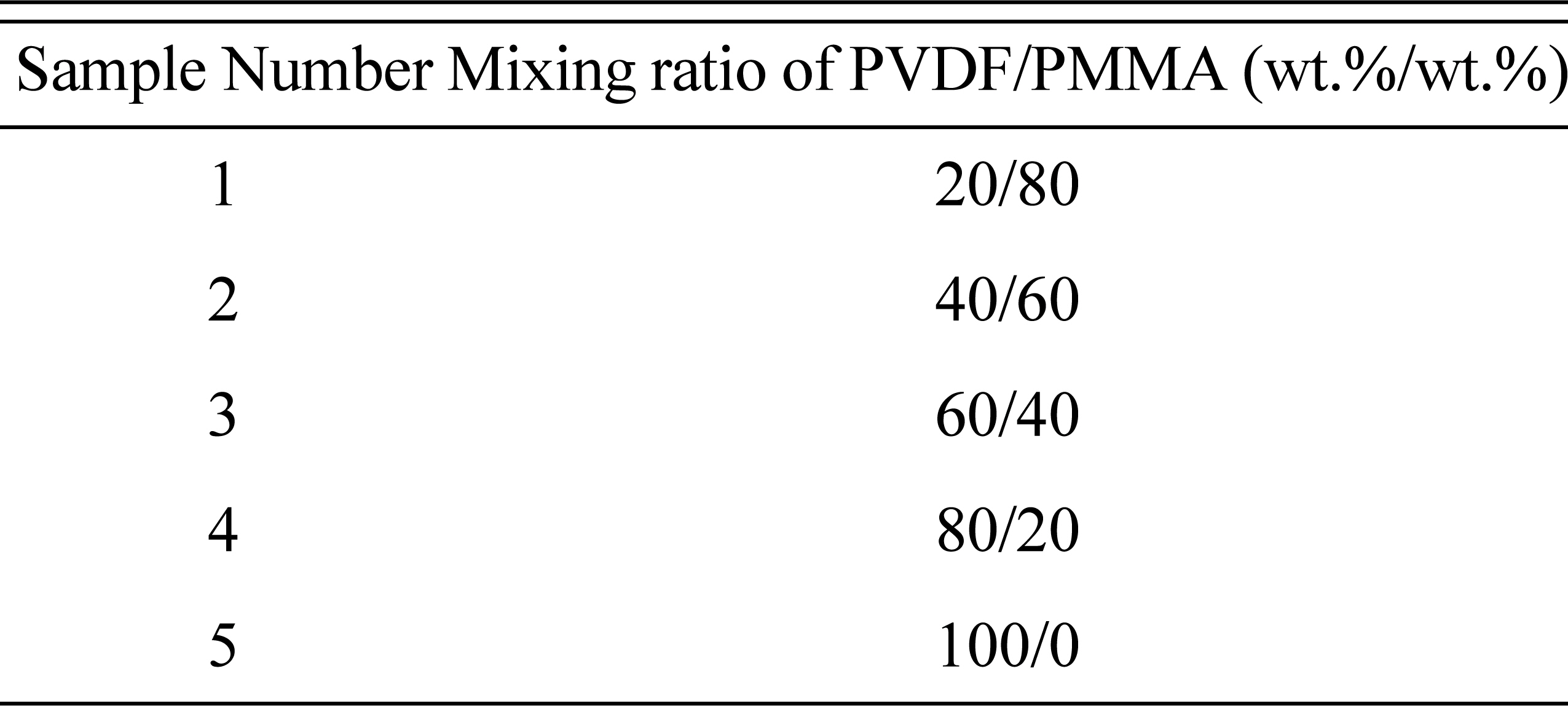
Sample preparation of PVDF/PMMA blend with different mixing ratio.
2.2 Characterization and Analysis
2.2.1 Polarization microscopic observation and X-ray diffraction studies
To characterize how the mixing ratio affected the crystallization behavior of the PVDF/PMMA coating materials, polarized optical microscopy (POM, Keyence VHX-1000) and X-ray diffraction analysis (Rigaku Japan, D/Max 2500) were used. For POM analysis, PVDF/PMMA films (1 cm × 1 cm) were prepared and placed on the microscope, and then the crystal-amorphous phase was observed. For X-ray diffraction analysis, PVDF/PMMA coating were mounted on the sample holder, and then the patterns were recorded in the range of 0-60° at a speed of 5°/min.
2.2.2 Thermal property Analysis
The thermal properties of PVDF/PMMA were evaluated by differential scanning calorimetry (DSC, Q10, USA) for different PVDF/PMMA mixing ratios. The PVDF/PMMA samples (~10 mg) were placed in an aluminum pan and heated from 25℃ to 200℃ at a 10℃/min heating rate, and then cooled to 25℃ at a 10℃/min cooling rate while purging with nitrogen gas. From the analysis, the melting (Tm) and crystallization temperatures (Tc) of PVDF/PMMA coatings were measured for different PVDF/PMMA mixing ratios.
2.2.3 Electrochemical impedance analysis
Electrochemical impedance spectroscopy (EIS) was performed to evaluate the corrosion protection performance of PVDF/PMMA-coated carbon steel with different mixing ratios. PVDF/PMMA-coated carbon steel specimens were immersed in a 3.5 wt.% NaCl solution at 40℃, and the effects of diffusive electrolyte accumulation on the corrosion-protective PVDF/ PMMA coatings on carbon steel were studied. A three-electrode system was applied during the EIS analysis of the PVDF/PMMA-coated carbon steel, including a working electrode (exposed area: 6.28 cm2), a saturated calomel reference electrode, and a platinum counter electrode (Fig. 1). The applied sine wave amplitude and frequency were 20 mV and 100 kHz to 10 mHz, respectively. An equivalent circuit model was used to evaluate the corrosion process of PVDF/PMMA-coated carbon steel.
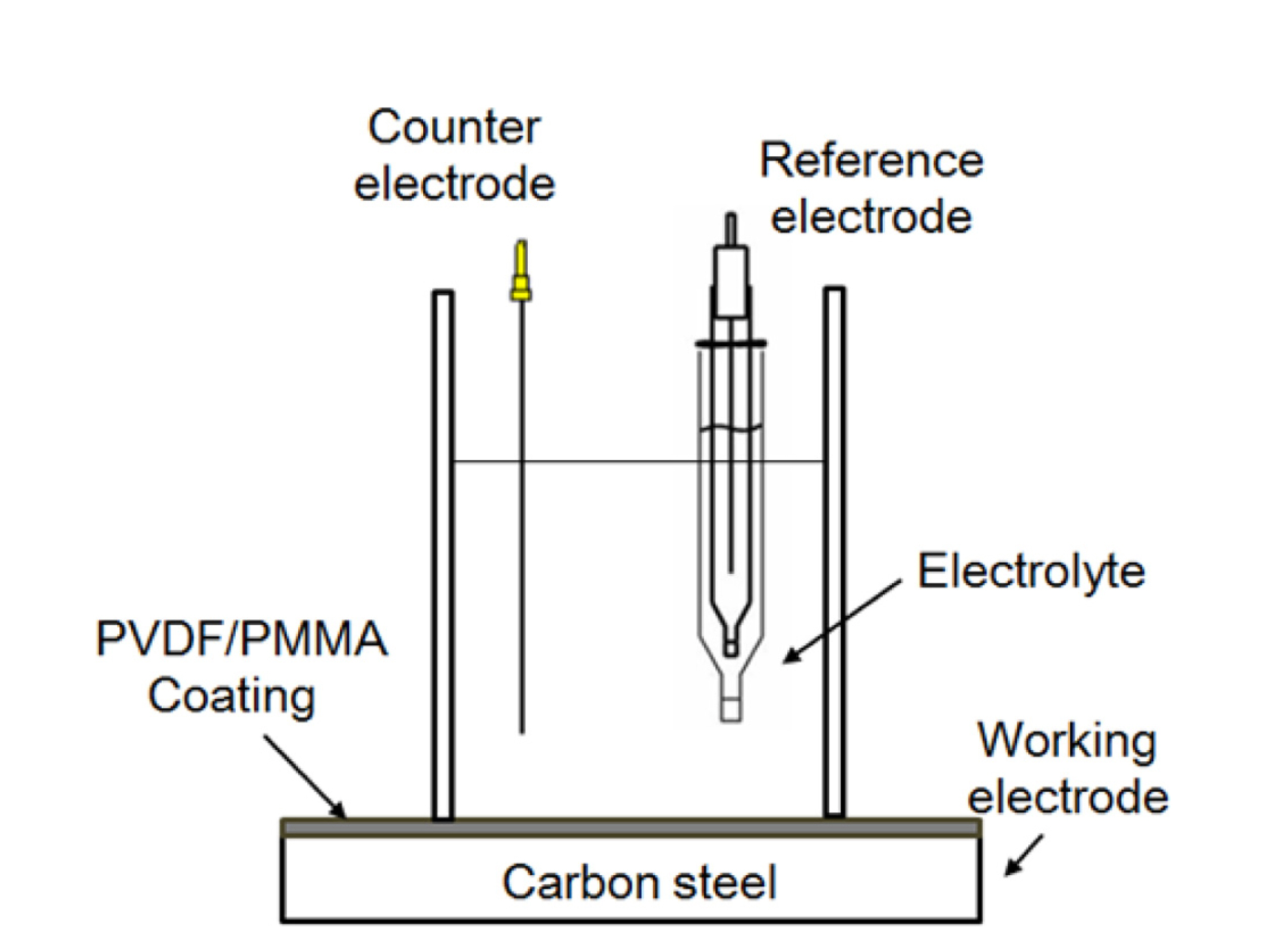
Schematic diagram of three-electrode EIS apparatus.
In the EIS spectrum analysis, the coating resistance (Rc), coating capacitance (Cc), charge transfer resistance (Rct) and double layer capacitance (Cdl) of PVDF/PMMA-coated carbon steel were measured in terms of its immersion time in 3.5 wt.% NaCl. Consequently, the accumulation of electrolytes into the coating and corrosion behavior of carbon steel was evaluated using the Rc, Cc, Rct, and Cdl values.
3. Results and Discussion
3.1 Crystal formation of PVDF/PMMA coatings by mixing ratio
The melting (Tm) and crystallization temperatures (Tc) were measured using DSC for different PVDF/PMMA mixing ratios (Fig. 2). The melting temperature decreased from 163℃ to 150℃ with increasing PMMA content; however, no clear melting temperature was observed when the PMMA content was 80 wt.% due to the dominant amorphous PMMA phase. The crystallization temperature also decreased, from 135℃ to 119℃, as the PMMA fraction increased to 40 wt.%; however, no crystallization temperature was observed when the PMMA volume exceeded 60 wt.%. In addition, exothermic heat flow due to crystallization decreased with increasing PMMA content, indicating decreasing crystal formation in the PVDF/PMMA coating film. Therefore, the blending ratio of PVDF/PMMA is an essential factor in studying the thermal behavior of the coating, and it can affect the formation of the crystal in them.
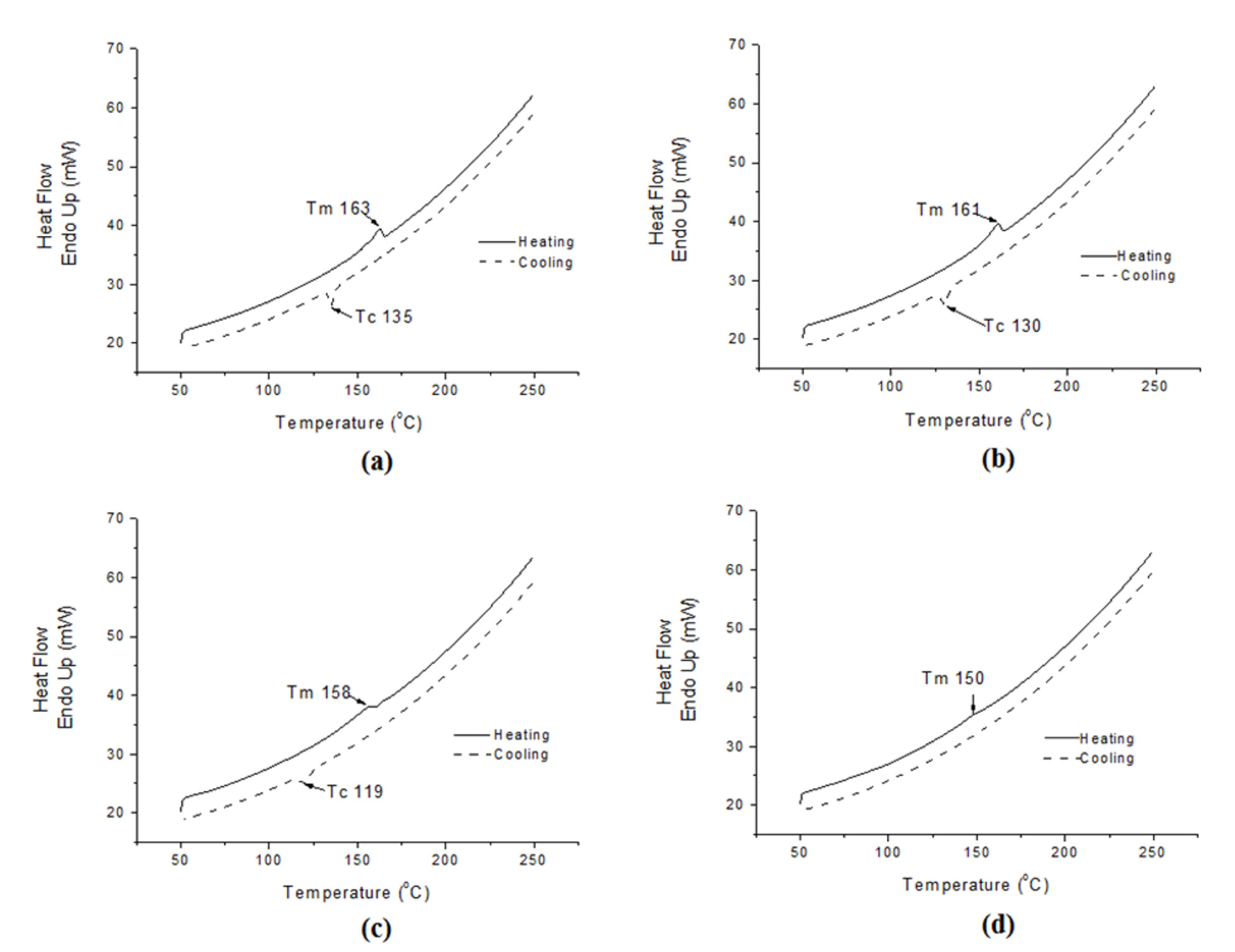
DSC analysis of PVDF/PMMA coating with different mixing ratio: (a) PVDF 100wt%, (b) PVDF 80wt%, (c) PVDF 60wt% and (d) PVDF 40wt%.
The formation of crystals on PVDF/PMMA coating films was observed by polarized optical microscopy by varying the PVDF/PMMA mixing ratio. The films were heated to 200℃ to entirely melt them, then cooled to 25℃ in air. Fig. 3 shows a polarized optical micrograph of PVDF/PMMA coating films for different mixing ratios. The 20 and 40 wt.% PVDF-blended coatings show many crystal seeds (white dots in Fig. 3 (d)), but no crystal phase growth in the coating film. On the other hand, the PVDF/PMMA coating films containing 60 and 80 wt.% PVDF had shown the formation of Maltese cross-pattern spherulite crystal structures (Fig. 3 (b) and (c)) with amorphous domains. The size of the spherulite crystals was 10-20 μm. When the PVDF fraction was increased to 100 wt.%, the sizes of the spherulite crystals increased to 30-40 μm, while their shape became more perfect (Fig. 3 (a)). Consequently, crystal formation was more apparent on PVDF/PMMA coating films with higher PVDF fraction, and agreed well with the DSC results showing crystallization exothermic heat flow. Fig. 4 shows the X-ray diffractograms of PVDF/PMMA coating films for different PVDF/PMMA mixing ratios. α-phase crystal peaks of PVDF were observed at 18.21°, 19.97° and these peaks increased in intensity with increasing PVDF contents; however, when the PVDF contents were 40 wt.%, only broad PMMA amorphous peak were observed. Consequently, X-ray diffraction results were agreed well with the results of polarized optical microscopy.

Polarized optical microscopic images of PVDF/PMMA coating with different mixing ratio: (a) PVDF 100wt%, (b) PVDF 80wt%, (c) PVDF 60wt% and (d) PVDF 40wt%.

X-ray diffractograms of PVDF/PMMA coating with different mixing ratio.
3.2 Corrosion protection performance of PVDF/PMMA coatings by mixing ratio
The corrosion protection performance of PVDF/PMMA-coated carbon steel was examined by EIS, after immersion in a 3.5 wt.% NaCl aqueous solution [16-20]. Fig. 5 (a) shows the EIS bode spectrum of PVDF/PMMA 20/80 (w/w)-coated carbon steel as a function of immersion time. The impedance modulus |Z| at 0.01 Hz was 5.2 × 10⁹ Ω cm2 after a 2-h immersion, and then dramatically decreased to 3.2 × 10⁵ Ω cm2 after an immersion time of 594 h. Additionally, the charge transfer resistance (Rct) and double layer capacitance (Cdl) were measured after an immersion time of 4 h. Fig. 7 (a) shows the Nyquist plot of PVDF/PMMA 20/80 (w/w)-coated carbon steel as a function of immersion time. Rct and Cdl were measured after 4-h immersion in 3.5 wt.% NaCl solution. After 4 h of immersion, Rct decreased and Cdl increased with increasing immersion time (Fig. 8), indicating an increase in the corroded area on the carbon steel underneath the PVDF/PMMA coating due to delamination. This also indicates that water permeated into the PVDF/PMMA 20/80 (w/w) coating during the immersion period, leading to reduced Rc and increased Cc, and consequently, a decrease in impedance modulus. The delamination was also confirmed at the interface between the coating and carbon steel by measuring Rct and Cdl.
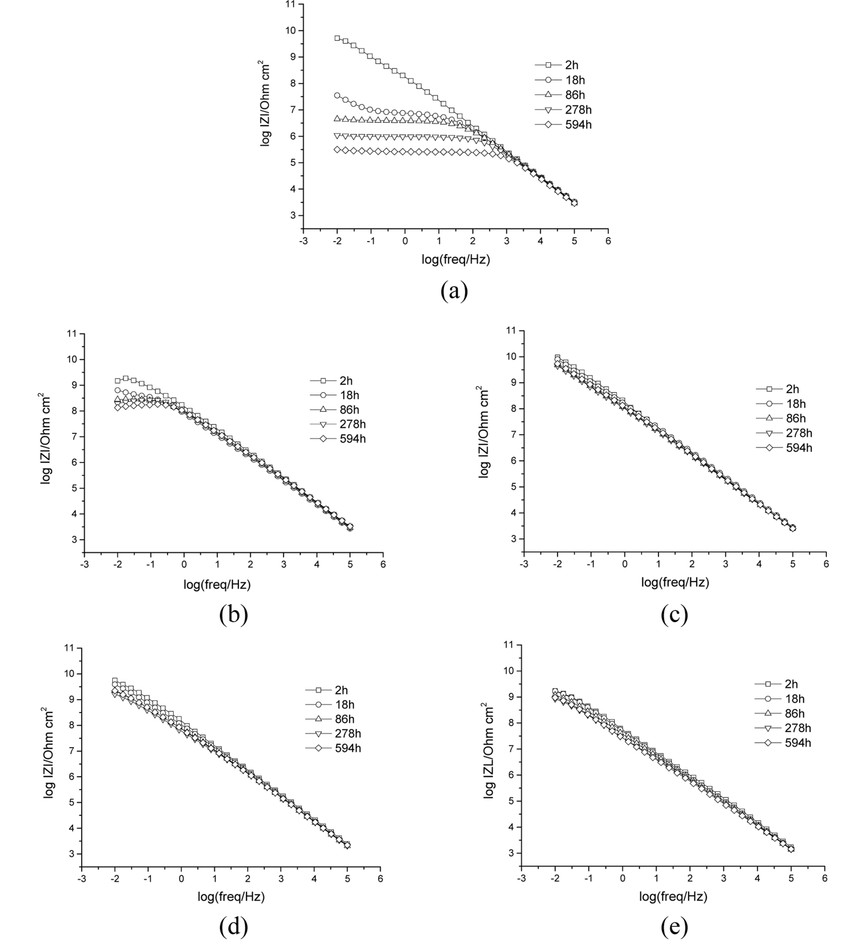
EIS spectra in Bode plot for PVDF/PMMA coating with different mixing ratio: (a) PVDF 20wt%, (b) PVDF 40wt%, (c) PVDF 60wt%, (d) PVDF 80wt%, (e) PVDF 100wt%.
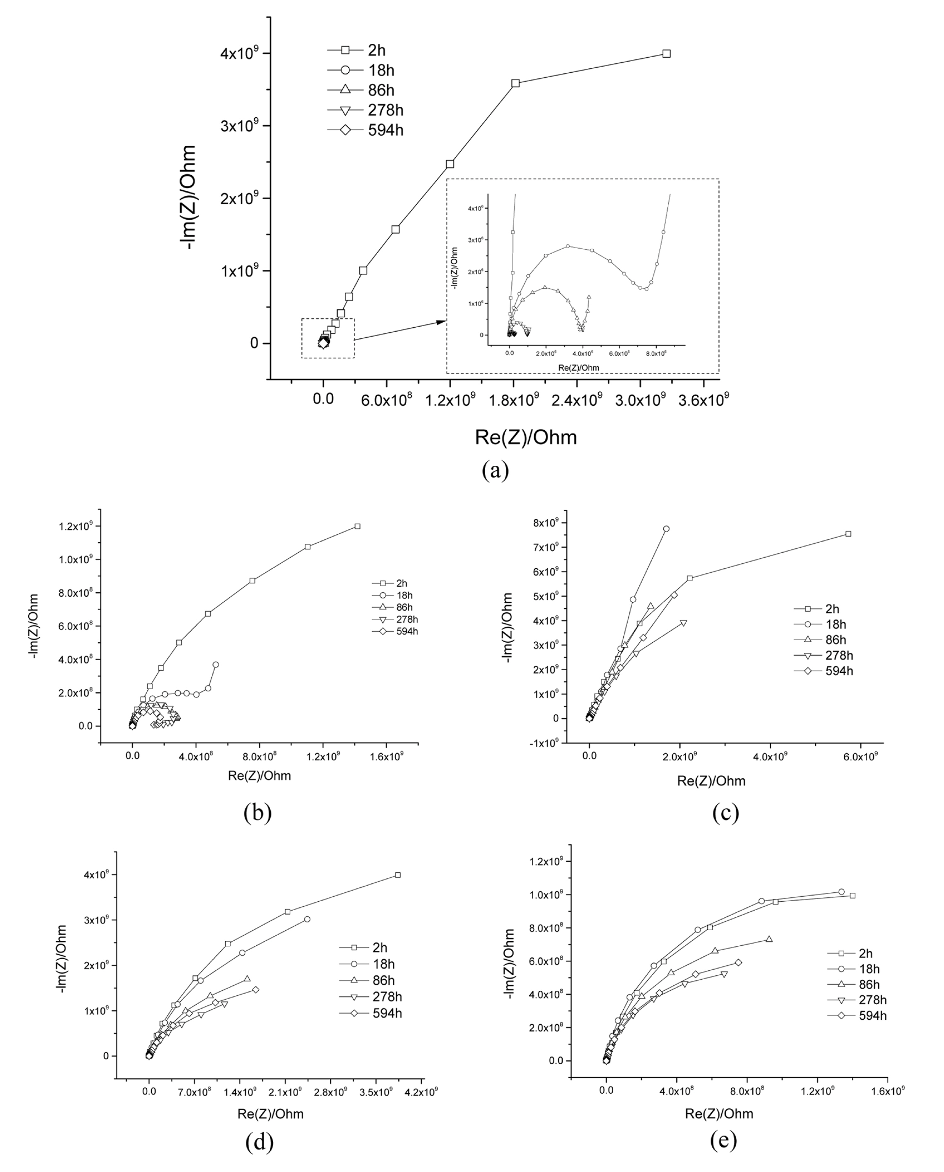
Nuquist plot of EIS analysis in terms of immersion time in 3.5 wt% NaCl solution: (a) PVDF 20wt%, (b) PVDF 40wt%, (c) PVDF 60wt%, (d) PVDF 80wt%, (e) PVDF 100wt%.
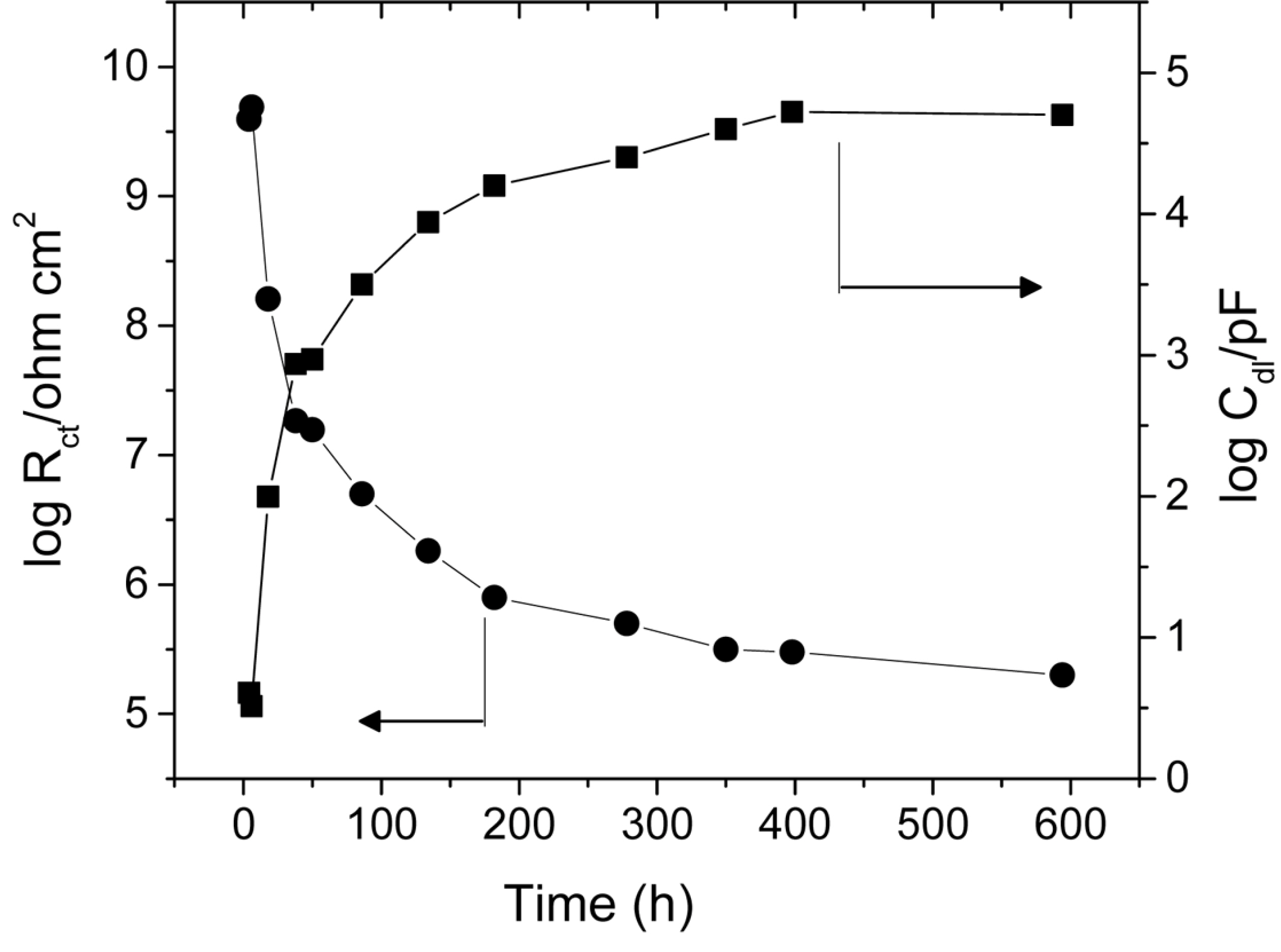
Charge transfer resistance (Rct) and Double-layer capacitance (Cdl) changes in terms of immersion time in 3.5wt% NaCl solution (PVDF 20 wt.%).
Fig. 5 (b) shows the EIS analysis results of PVDF/PMMA 40/60 (w/w)-coated carbon steel as a function of immersion time. The impedance modulus |Z| at 0.01 Hz was 1.5 × 10⁹ Ω cm2 after a 2-h immersion, slightly decreasing to 1.4 × 10⁸ Ω cm2 after 594 h of immersion. Rct and Cdl were not observed during the immersion time. The decreasing impedance was caused by the absorption of water into the coating; however, in this case, coating delamination from the carbon steel substrate did not occur. Fig. 5 (c) shows the EIS analysis results of PVDF/PMMA 60/40 (w/w)-coated carbon steel as a function of immersion time. The impedance modulus |Z| at 0.01 Hz was 9.5 × 10⁹ Ω cm2 after 2 h of immersion; it shows nearly constant values after 594 h of immersion. The Rct and Cdl were not observed during the immersion time. The constant impedance value indicates relatively lower water permeation into the coating and excellent barrier protection capability against corrosion. Fig. 5 (d) describes the EIS analysis results of PVDF/PMMA 80/20 (w/w)-coated carbon steel as a function of immersion time. The impedance modulus |Z| at 0.01 Hz was 5.5 × 10⁹ Ω cm2 after 2 h of immersion and slightly decreased to 2.2 × 10⁹ Ω cm2 after an immersion time of 594 h. Again, Rct and Cdl were not observed during the immersion time. The slightly decreased impedance value indicates low water permeation into the coating. Fig. 5 (e) shows the EIS analysis results of 100 wt.% PVDF-coated carbon steel as a function of immersion time. The impedance modulus |Z| at 0.01 Hz was 1.7 × 10⁹ Ω cm2 after 2 h of immersion, decreasing to 9.6 × 10⁸ Ω cm2 after immersion for 594 h. The Rct and Cdl were, again not observed during the immersion time.
The impedance moduli at 10 mHz for various PVDF/PMMA-blended coatings are shown in Fig. 6 as functions of immersion time. The corrosion resistance performance decreased in the following order: 60, 80, 100, 40, and 20 wt.% of the PVDF fraction in the PVDF/PMMA blended coatings.

Impedance modulus at 10mHz for PVDF/PMMA coating in terms of immersion.
The equivalent electrical circuit model for PVDF/PMMA-blended coating systems is shown in Fig. 9. These models are used widely to describe water penetration and corrosion reaction of organic coating coated metal systems [21-22]. Rs is the electrolyte solution resistance, Rc is the coating resistance, Cc is the coating capacitance, Rct is the charge-transfer resistance, and Cdl is the double layer capacitance. The EIS results were curve-fitted and the electrical circuits established (Fig. 9 (a) and (b)) for 40 wt.% to 100% and 20 wt.% PVDF-to-PMMA ratio coating systems, respectively.

Establishment of equivalent circuits for (a) PVDF contents (40 to 100 wt%) and (b) PVDF contents (20wt%).
Based on the EIS results, a 60 wt.% of PVDF-coated carbon steel shows the corrosion protection performance among the specimens studied. Coating delamination and corrosion reactions were not observed except for 20 wt.% PVDF-coated carbon steel. An analysis of the crystallization of the PVDF/PMMA coating with different mixing ratios reveals that water permeability into the amorphous/crystal mixture structure is lower than that of a perfect-crystal domain, indicating better corrosion protection and coating, with the fully amorphous domain showing the worst corrosion protection.
4. Conclusions
The conclusions drawn from the study are as follows:
Maltese cross-pattern spherulite crystals were formed in the PVDF/PMMA coating film that became more apparent with increasing PVDF fraction.
60 wt.% PVDF-coated carbon steel showed the highest corrosion protection performance, and delamination and corrosion reactions were observed for 20 wt.% PVDF. Further, the corrosion protection performance of amorphous/crystal mixture structures (PVDF/PMMA, 60/40 (w/w)) was better than that of amorphous domains, and perfect crystal domain structure was confirmed by the EIS results.
Acknowledgements
This work was supported by a Research Grant of Pukyong National University (2017), and This work was supported by the Korea Institute of Energy Technology Evaluation and Planning(KETEP) and the Ministry of Trade, Industry & Energy (MOTIE) of the Republic of Korea (No. 20174010201460)