Comparison of a Cation Exchange Membrane and a Ceramic Membrane in Electrosynthesis of Ammonium Persulfate by a Pilot Experimental Study
Article information
Abstract
In order to improve the current efficiency and reduce the energy consumption in the electrosynthesis of ammonium persulfate, electrolytic properties of a perfluorosulfonic cation exchange membrane named PGN membrane and the Al2O3 ceramic membrane in the electrosynthesis of ammonium persulfate were studied and compared in a pilot electrolytic cell using a welded platinum titanium as the anode and a Pb-Sb alloy as the cathode. The effect of cell voltage, electrolyte flow rate and electrolysis time of the electrolytes on the current efficiency and the energy consumption were studied. The results indicated that the PGN membrane could improve current efficiency to 95.12% and reduce energy consumption to 1110 kWh t−1 (energy consumption per ton of the ammonium persulfate generated) under the optimal operating conditions and the highest current efficiency of the Al2O3 ceramic membrane was 72.61% with its lowest energy consumption of 1779 kWh t−1. Among 5 times of the electrolysis of the electrolytes, the lowest current efficiency of the PGN membrane was 85.25% with the highest energy consumption of 1244 kWh t−1 while the lowest current efficiency of the Al2O3 ceramic membrane was 67.44% with the highest energy consumption of 1915 kWh t−1, which suggested the PGN membrane could be used in the 5-stage electrolytic cell for the industrially continuous electrosynthesis of ammonium persulfate. Therefore the PGN membrane can be efficient to improve the current efficiency and reduce the energy consumption and can be applied in the industrial electrosynthesis of ammonium persulfate.
1. Introduction
Ammonium persulfate ((NH4)2S2O8) with strong oxidizing property is widely used in the chemical industry, the light industry, the electronics, the petroleum industry and the food industry [1–3]. At present, the electrolytic production of ammonium persulfate is generated from the electrolysis of ammonium sulfate solution and then the crystallization of the ammonium persulfate forms by freezing the solution [4]. The principle of electrosynthesis of ammonium persulfate is as follows [5]:
Anode reaction:
Cathode reaction:
Anodic competing oxygen reaction:
Cathodic side reaction:
E0: standard electrode potential.
SHE: standard hydrogen electrode.
Nowadays, the ceramic membrane is the main membrane used in the industrial electrosynthesis of ammonium persulfate. Although the price of the ceramic membrane is lower than that of the ion exchange membranes, its lifespan is shorter with higher energy consumption, which increases the production costs [6–7]. At present, improving current efficiency and reducing energy consumption are important research aspects in the electrosynthesis of ammonium persulfate mainly involving anode materials, cathode materials, electrolytic cell structure, additives and the membranes [8–10].
In past decades, ion exchange membranes have been widely used in the electrodialysis, the water elctrolysis and other production processes [11–13]. And ion exchange membranes have played a significant role in improving current efficiency and reducing energy consumption in the electrosynthesis of ammonium persulfate in recent years [14–15].
The ion exchange membranes used in the chloralkali industry such as the Nafion® 427 [16] membrane and some new ion-exchange membranes [17] have been extensively studied in the electrosynthesis of ammonium persulfate using the laboratory device [18], however, there are few reports about their industrial applications in the electrosynthesis of ammonium persulfate. Wang Chao et al. [19] investigated the electrolytic properties of four cation exchange membranes in the electrosynthesis of ammonium persulfate in a lab scale electrolytic cell and obtained a self-made perfluorosulfonic ion exchange membrane, named PGN membrane that could improve the current efficiency and reduce the energy, which could not fully reflect the performance of the ion exchange membranes in the industrial electrosynthesis of ammonium persulfate. Besides, there are few reports about the comparison of the ion exchange membranes and the ceramic membranes in pilot elecrosynthesis of ammonium persulfate. In addition, some ion exchange membranes with low the mechanical strength such as Nafion® 117 is not easy to install in a pilot electrolytic cell.
In this paper, electrolytic performance of a perfluorosulfonic cation exchange membrane named PGN membrane in our previous work[19] and an Al2O3 ceramic membrane in the electrosynthesis of ammonium persulfate was studied and compared by a pilot electrolytic cell in a company to improve the current efficiency and reduce the energy consumption in the industrial electrosynthesis of ammonium persulfate.
2. Experimental
2.1. Materials and chemicals
The pilot experiment was carried out in a company producing ammonium persulfate in Hebei province. Ammonium sulfate ((NH4)2SO4), Sulfuric acid (H2SO4) and ammonium persulfate ((NH4)2S2O8) were provided by the company. Chemicals for volumetric titration analysis (potassium permanganate (KMnO4) and ferrous sulfate (FeSO4)) used were of analytical grade and were purchased from Tianjin Hongyan Chemical Reagent Factory.
The PGN membrane is made by solution coasting technology combined with polytetrafluoroethylene reinforced mesh with the equivalent weight of 0.8 (mmol g−1), the water content of 20% at 25°C and the density of 2.1 g cm−3 with the proper pH ranging from 1 to 14 [19]. The Al2O3 ceramic membrane was purchased from Beijing University of Chemical Technology. The physical properties of the two membranes are shown in Table 1 and Table 2.

The properties of the PGN membrane

The properties of the Al2O3 ceramic membrane
From Table 1 and s 2, it can be seen that the thickness of the PGN membrane is lower with lower strength compared with the Al2O3 ceramic membrane. However, the mechanical strength of the PGN membrane is sufficient with the reinforced mesh and its electrical conductivity is higher than that of the Al2O3 ceramic membrane. Although the thermal stability range of the PGN membrane is smaller than that of the Al2O3 ceramic membrane, the thermal stability range of the two membranes can meet the demand of the temperature of 20°C–40°C in the industrial electrosynthesis of ammonium persulfate.
2.2 Pilot Experimental electrolytic cell
Three dimensional diagram of the pilot electrolytic cell used in the experiment was shown in Fig. 1.

Three dimensional diagram of the pilot experimental electrolytic cell
As shown in Fig. 1, the anode and the cathode were placed in a polypropylene cuboid electrolytic cell. The anode chamber consisted of the anode, the membrane and the anode frame. Platinum wire with a total surface area of 1071.45 cm2 was welded onto the titanium plates of the anode that formed five cuboid cavities connected by circular titanium pipes as a heat exchanger. And the temperature of the anolyte was adjusted by cooling water flowing through the titanium pipes. The cathode was made from a lead antimony alloy orifice plate and the temperature of the catholyte was adjusted by a coil heat exchanger surrounding the cathode. The membrane with an effective surface area of 0.57 m2 was mounted on both sides of the anode frame and the membrane was supported by the polypropylene rib plate. The average distance between the membrane and the titanium plates of the anode was 1 cm with the average distance of 1 cm between the membrane and the cathode plate.
2.3 Experimental design
As shown in Fig. 2, the experimental apparatus for the pilot electrosynthesis of ammonium persulfate consists of a power converter (KGDF-1000 A/30V) from Beijing Chunshu Rectifier Co., Ltd., two flow regulating valves (Q11F-10S) from Ningbo Arkema Pipe Valve Technology Co., Ltd., a clamp type DC ammeter (BM2000B) from Shenzhen Riverside Electronic Technology Co., Ltd. and two plastic rotor flowmeters (ZN-LZS-15) from Jiangsu Instrument Technology Co., Ltd.

Diagram of the experimental apparatus
All pilot experiments were carried out using constant voltage method. As for studying the effect of cell voltage and electrolyte flow rate on current efficiency and energy consumption, the electrolytes were continually pumped from the inlet reservoir to the electrolytic cell and then flowed into the corresponding outlet reservoir and then, the anolyte was cooled and crystallized to produce ammonium persulfate particles with the catholyte recycled to prepare the inlet catholyte again. The cell voltage ranged from 4 V to 6.5 V and the electrolyte flow rate ranged from 1 L min−1 to 2 L min−1 with the temperature range of the anolyte and the catholyte from 30°C to 35°C. As for studying the effect of electrolysis times of the electrolytes on current efficiency and energy consumption, when one time electrolysis of the electrolytes was finished, the electrolytes were directly pumped from the outlet inlet reservoir to the corresponding inlet reservoir and then flowed into the electrolytic cell for the next electrolysis experiment. Samples were extracted from the anolyte outlet reservoir for analysis when each experiment was finished.
The electrochemical reaction was operated with the anolyte of 460 g L−1 (NH4)2SO4 and 90 g L−1 (NH4)2S2O8 and the catholyte of 400 g L−1 (NH4)2SO4 and 49 g L−1 H2SO4 that were the same as those in the industrial electrosynthesis of ammonium persulfate.
2.4 Analytical methods
The amount of the ammonium persulfate generated was determined using the potassium permanganate method. Samples of solutions were treated by excess 0.2 mol L−1 standard FeSO4 solution, which generated Fe2(SO4)3 with surplus FeSO4. The surplus FeSO4 was measured using 0.01 mol L−1 standard KMnO4 solution that could be used as an indicator to determine the end point of the titration.
The concentration of the ammonium persulfate (c, mol L−1) was calculated using Eqn. (1):
where c1 and c2 are the concentration of the FeSO4 solution and the KMnO4 solution, respectively, mol L−1; n is the number of electrons involved in the electrode reaction; V0, V1 and V2 are the titration volume of samples, FeSO4 solution and KMnO4 solution, respectively, L.
The experimental current efficiency (η, %) was calculated using Eqn. (2):
And
Therefore,
where c3 and c4 are the concentration of ammonium persulfate before electrolysis and after electrolysis, respectively, mol L−1; V is the total volume of the anolyte flowing through the anode chamber, L; Q is the electrolyte flow rate, L s−1; F is the Faraday constant, 96485 C mol−1; t is the total time of the constant cell voltage applied, s; I is the working current, A.
The experimental energy consumption per ton of the ammonium persulfate generated (W, kWh t−1) is calculated using Eqn. (5):
where M is the molar mass of ammonium persulfate, g mol−1; U is the constant cell voltage applied, V.
3. Results and Discussion
3.1 The effect of cell voltage on current efficiency and energy consumption
As shown in Fig. 3, the current efficiency of the PGN membrane and the Al2O3 ceramic membrane gradually increased with the increase of the cell voltage and reached their maximum value, 94.39% and 72.61% at the cell voltage 4.5 V and 5.5 V, respectively. As for the two membranes, the anode reaction producing ammonium persulfate was promoted with the oxygen evolution reaction inhibited when the current density increased, which increased the current efficiency. Besides, the S2O82− ion in the anolyte could pass through the Al2O3 ceramic membrane to the catholyte at a low cell voltage starting the cathodic side reaction because the Al2O3 ceramic membrane is a kind of mechanical membrane without the selective permeability to the ions[20]. With the increase of the cell voltage, the electric field force of the S2O82− ions in the anolyte increased improving the resistance of the S2O82− ions in the anolyte migrating to the catholyte, which improved the current efficiency. The current efficiency of the PGN membrane and the Al2O3 ceramic membrane gradually declined with cell voltage increasing beyond their optimal values, which was attributed to the enhanced oxygen evolution reaction caused by the increased anode potential and the increase of the electrolyte bubble coverage of the anode electrode reducing the effective area of the anode electrode when cell voltage increased[21]. As can be seen from Fig. 3, the cation exchange membrane named the PGN membrane has a good barrier on the S2O82− and can effectively prevent the S2O82− ion in the anolyte from migrating to the catholyte thereby increasing the current efficiency [22].

Current efficiency of the PGN membrane and the Al2O3 ceramic membrane at different cell voltage at an electrolyte flow rate of 1.5 L min−1
Fig. 4 shows that the energy consumption of the PGN membrane and the Al2O3 ceramic membrane gradually declined and then gradually increased with the increase of the cell voltage, and reached their minimum values, 1119 kWh t−1 and 1779 kWh t−1 at the cell voltage of 4.5 V and 5.5 V, respectively. For the increase of the energy consumption of the PGN membrane and the Al2O3 ceramic membrane with the cell voltage increasing, on the one hand, the bubble rate in the electrolytes increased continuously with the increase of the cell voltage, which reduced the conductivity of the electrolytes [23]. On the other hand, the increase of the cell voltage also contributed to the increase of energy consumption to according to Eqn. (5).

Energy consumption of the PGN membrane and the Al2O3 ceramic membrane at different cell voltage at an electrolyte flow rate of 1.5 L min−1
The electrical conductivity and the selective permeability of the ions of the PGN membrane was higher resulting in lower membrane voltage drop and lower cell voltage compared with the Al2O3 ceramic membrane, which caused higher current efficiency and lower energy consumption at the same cell voltage.
3.2 The effect of electrolyte flow rate on current efficiency and energy consumption
As shown in Fig. 5, the current efficiency of the PGN membrane gradually increased with the electrolyte flow rate increasing at the cell voltage of 4.5 V and reached the maximum 95.12% at the electrolyte flow rate of 2 L min−1. On the one hand, the increase of the electrolyte flow rate promoted the mass transfer of the electrolytes improving the current efficiency. On the other hand, the increase of the electrolyte flow rate also reduced the bubble coverage of the electrodes increasing the effective surface area of the electrodes, which also improved the current efficiency [24]. After the electrolyte flow rate exceeded 1.5 L min−1, there was no significant increase in the current efficiency with the electrolyte flow rate increasing, which suggested that the mass transfer was not the reaction rate determining step at the electrolyte flow rate from 1.5 L min−1 to 2 L min−1 in the present system apparatus [18]. The current efficiency of the Al2O3 ceramic membrane gradually increased reaching its maximum value 72.61% at the electrolyte flow rate of 1.5 L min−1 and then reduced slightly with the increase of the electrolyte flow rate. As the electrolyte flow rate increased over 1.5 L min−1, some of the ions failed to transfer between the electrolyte and the Al2O3 ceramic membrane, which caused that the part of the electrolytes did not participate in the anode reaction and then flowed out of the anode chamber thereby reducing the current efficiency.

Current efficiency of the PGN membrane and the Al2O3 ceramic membrane at different electrolyte flow rate at the cell voltage of 4.5 V and 5.5 V, respectively
As shown in Fig. 6, the energy consumption of the PGN membrane gradually reduced with the electrolyte flow rate increasing at the cell voltage of 4.5 V and reached the minimum value of 1110 kWh t−1 at the electrolyte flow rate of 2 L min−1. With the increase of electrolyte flow rate, the energy consumption of the Al2O3 ceramic membrane increased and then declined at the electrolyte flow rate of 1.5 L min−1 reaching the minimum value of 1874 kWh t−1. As seen from Fig. 6, the energy consumption of the PGN membrane was lower compared with the Al2O3 ceramic membrane, which resulted from the higher current efficiency and the lower cell voltage of the PGN membrane according to Eqn. (5) due to its higher electrical conductivity.

Energy consumption of the PGN membrane and the Al2O3 ceramic membrane at different electrolyte flow rate at the cell voltage of 4.5 V and 5.5 V, respectively
3.3 Effect of the electrolysis time of electrolytes on current efficiency and energy consumption
Fig. 7 shows that the current efficiency of the PGN membrane and the Al2O3 ceramic membrane gradually declined as the electrolysis time of the electrolytes increased. After 5 times of the electrolysis, the current efficiency of the PGN and the Al2O3 ceramic membrane reached 85.25% and 67.44% respectively. With the increase of the electrolysis times of the electrolytes, the concentration of the S2O82− in the anolyte increased with the decline of the concentration of SO42− in the anolyte, which reduced the anodic production rate of ammonium persulfate and the current efficiency. In addition, the increasing concentration of the S2O82− in the anolyte also promoted the diffusion of the S2O82− from the anolyte to the catholyte because the Al2O3 ceramic membrane was a kind of the mechanical membrane, which also resulted in the decrease of the current efficiency.

Effect of the electrolysis time of electrolytes on current efficiency
As shown in Fig. 8, the energy consumption of the PGN membrane and the Al2O3 ceramic membrane gradually increased with the electrolysis time of the electrolytes increasing. After 5 times of the electrolysis of the electrolytes, the energy consumption of the PGN membrane and the Al2O3 ceramic membrane reached 1244 kWh t−1 and 1915 kWh t−1, respectively. On the one hand, the increase of electrolysis times reduced the current efficiency. On the other hand, the increase of electrolysis times caused that the concentration of the ions in the electrolytes continuously reduced, which resulted in the continuous reduce of the conductivity of the electrolytes leading to the increase of energy consumption.
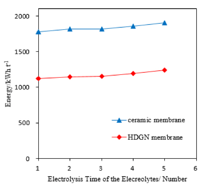
Effect of the electrolysis time of electrolytes on energy consumption
Nowadays, most of the studies on the electrosynthesis of ammonium persulfate by ion exchange membranes are carried out at the lab scale device. Nan Hu et al. [17] improved the current efficiency to 76.3% and reduced the energy consumption to 1485 kWh t−1 in the electrosynthesis of ammonium persulfate using several new developed self-made composite membranes in a small scale experiment, which could not fully reflect the electrolytic performance of the ion exchange membranes in the industrial electrosynthesis of ammonium persulfate. Wang Ying et al. [25] improved the current efficiency to 84.13% using the Nafion® 117 membrane with ammonium polyphosphate as the anode additive in the electrosynthesis of ammonium persulfate. But the Nafion® 117 membrane is not easy to install in a pilot electrolytic cell because of its low mechanical strength.
The electrolytic performance of PGN membrane and the Al2O3 ceramic membrane was studied and compared by a pilot electrolytic cell in a company of electrosynthesis of ammonium persulfate, which could better reflect the electrolytic performance of the ion exchange membrane in the industrial electrosynthesis of ammonium persulfate. Besides, the mechanical strength of the PGN membrane is sufficient with enhanced mesh.
Compared with the Al2O3 ceramic membrane, the PGN membrane with high electrical conductivity and the selective permeability of the ions has higher current efficiency and lower energy consumption in the pilot electrosynthesis of ammonium persulfate. It can be seen from Fig. 7 and Fig. 8 that the PGN membrane still has high current efficiency and low energy consumption after the 5 times of the electrolysis of the electrolytes, thus the PGN membrane can be used in the 5-stage electrolytic cell in the industrially continuous electrosynthesis of ammonium persulfate.
4. Conclusions
The results indicated that the current efficiency and the energy consumption of the PGN membrane and the Al2O3 ceramic membrane reached 95.12% and 1110 kWh t−1 at the cell voltage of 4.5 V and at the electrolyte flow rate of 2 L min−1 and 72.61% and 1779 kWh t−1 at the cell voltage of 5.5 V and at the electrolyte flow rate of 1.5 L min−1, respectively, using the anolyte with a mixture of 460 g L−1 (NH4)2SO4 and 90 g L−1 (NH4)2S2O8 and the catholyte with a mixture of 400 g L−1 (NH4)2SO4 and 49 g L−1 H2SO4 in the pilot electrosynthesis of ammonium persulfate. After 5 times of the electrolysis of the electrolytes, the minimum current efficiency of the PGN membrane was 85.25% with the maximum energy consumption of 1244 kWh t−1 while the minimum current efficiency of the Al2O3 ceramic membrane was 67.44% with the maximum energy consumption of 1915 kWh t−1, which suggested the PGN membrane could be applied to the 5-stage electrolytic cell for the industrially continuous electrosynthesis of ammonium persulfate. Besides, the mechanical strength of the PGN membrane was sufficient with enhanced mesh. Therefore, the PGN membrane will have a good application prospects in the industrial electrosynthesis of ammonium persulfate compared with the Al2O3 ceramic membrane.