Synthesis and Applications of Dicationic Iodide Materials for Dye-Sensitized Solar Cells
Article information
Abstract
Dye-sensitized solar cells (DSSCs) have been receiving growing attentions as a potential alternative to order photovoltaic devices due to their high efficiency and low manufacturing cost. DSSCs are composed of a photosensitizing dye adsorbed on a mesoporous film of nanocrystalline TiO2 as a photoelectrode, an electrolyte containing triiodide/iodide redox couple, and a platinized counter electrode. To improve photovoltaic properties of DSSCs, new dicationic salts based on ionic liquids were synthesized. Quite comparable efficiencies were obtained from electrolytes with new dicationic iodide salts. The best cell performance of 7.96% was obtained with dicationic salt of PBDMIDI.
1. Introduction
In the solar industry, now inorganic solid-state junction devices are challenged by emergence of a third generation of cell, based on nanocrystalline and conducting polymers films. These offer the prospective of very low cost fabrication and present attractive features that facilitate market entry[1–4]. The dye-sensitized solar cells (DSSCs), nanocrystalline solar cells, have been regarded as one of the most promising next-generation solar cells. DSSCs are composed of various materials such as titanium dioxide (TiO2), dyes, redox couple electrolyte and transparent conducting oxides. TiO2 is an n-type wide band gap semiconductor, which is transparent for visible light. DSSCs convert visible light energy to electrical energy through charge separation in sensitizer dyes on a surface of TiO2.
The interception of the oxidized dye by the electron donor, normally I−, is in the microsecond time domain. For a turnover number, that is, the cycle life of the sensitizer in the DSSC device, to be above, which is required for a DSSC lifetime of 20 years in outdoor conditions, the lifetime of the oxidized dye must be >100 s if the regeneration time is 1 μs. This is achieved by the best-performing Ru complexes.
The reduction of the oxidized sensitizer (S+) by iodide follows most likely the following reaction mechanism:
The first step is most likely a one-electron transfer reaction between S+ and I−. The oxidation of iodide to free iodine radical (I•) is, however, unlikely for energetic reasons: U0(I•/I−) is +1.33 V vs. NHE in aqueous solutions and has been reported to +1.23 V vs. NHE in acetonitrile [5], which is more positive than the U0(S+/S) of most of the dyes that are used as sensitizers in DSCs. The redox potential of the iodine radical bound to the dye (S ⋯ I) will be less positive in potential, and the formation of a (S ⋯ I) complex is therefore a likely first step in the dye regeneration. Addition of a second iodide leads to the formation of a (S ⋯ I2 −•) complex, which can dissociate into ground-state dye S and I2 −•. Finally, I2 −• disproportionates under the formation of triiodide and iodide. The second-order rate constant for this reaction is 2.3 × 10¹⁰ M−1s−1 in acetonitrile. Evidence for the formation of intermediate dye-iodide complexes comes from nanosecond laser spectroscopy studies.
As shown above, iodide ions are playing very important roles in turn over cycles[6–10], and their structures also affect the whole device functions. Herein, we suggest a newly synthesized types of cations for iodide release, and applied to DSC systems.
2. Experimental
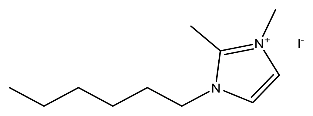
All chemicals and solvents used over the course of this investigation were of reagent grade purchased from Aldrich or Fluka, except 1-hexyl-2,3-dimethyl imidazolium iodide(C-tri).
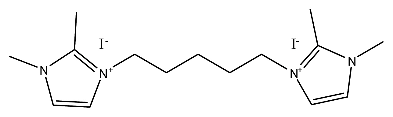
2.1 Synthesis of 3,3′-(pentane-1,5-diyl)bis(1,2-dimethyl-1H-imidazol-3-ium) diiodide [PBDMIDI]
1,2-dimethyl imidazole (1.335 g, 13.88 mmol) and 1,5-diiodo pentane (1.500 g, 6.439 mmol) in 5mL of toluene was heated to 110°C(reflux) for 12 h. The solvent was removed by rotary evaporator. After this step, white solid was obtained. For recrystallization the white solid was dissolved in acetonitrile and then added excess ethyl acetate. The mixture of products and the solvent was filtrated. The filtrated material was dried in a vacuum oven for 2 h. Finally, pure white powders were obtained at yield of 96.2% (2.3 g). The final product was confirmed with NMR. 1H NMR (D2O) (Fig. S1)
2.2 Synthesis of 3,3′-(2,2′-oxybis(ethane-2,1-diyl))bis(1,2-dimethyl-1H-imidazol-3-ium) diiodide [EBDMIDI]
The same procedure was used, with 1.28 g (13.8 mmol) of 1,2-dimethyl imidazole, and 1.45 g (4.45 mmol) of 2-iodoethyl ether in 5mL of toluene. 2.18g, 94.6% yield. 1H NMR (D2O) (Fig. S2)
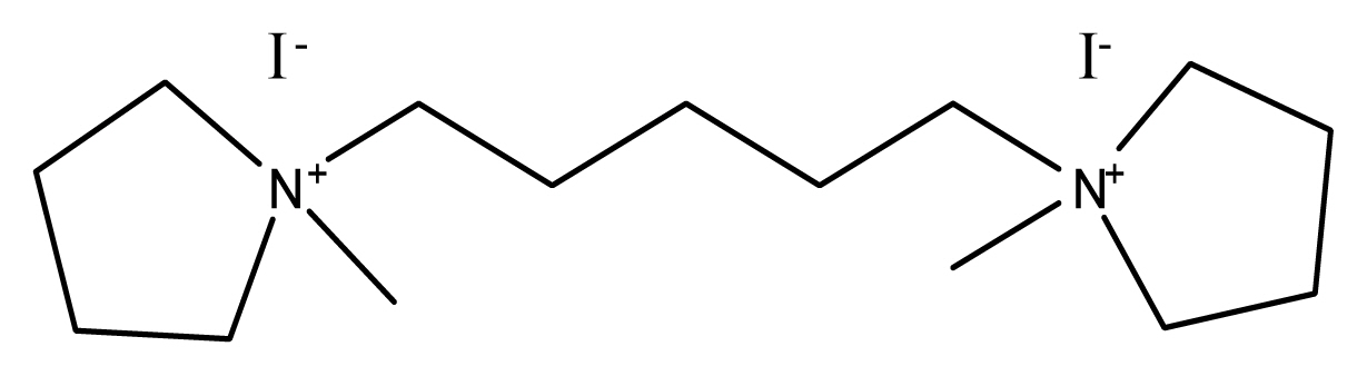
2.3 Synthesis of 1,1′-(pentane-1,5-diyl)bis(1-methylpyrrolidinium) diiodide [PBMPyDI]
The same procedure was used, with 1.11 g (13.0 mmol) of N-methylpyrrolidine, and 1.41 g (4.33 mmol) of 2-iodoethyl ether in 5mL of toluene. 2.05 g, 95.6% yield. 1H NMR (D2O) (Fig. S3)
2.4 Preparation of Electrolytes
1-hexyl-2,3-dimethyl imidazolium iodide (HDMII) was used to prepare the reference electrolyte. 0.6 M 1-hexyl-2,3-dimethyl imidazolium iodide (HDMII), 0.1 M lithium iodide (LiI), 0.05 M iodine (I2), 0.1 M guanidinium thiocyanate and 0.5 M tert-butyl pyridine (TBP) dissolved in acetonitrile and mixture of acetonitrile, propylene carbonate, ethylene carbonate and γ-Butyrolactone. In order to investigate the different kinds of dicationic iodide on photovoltaic performance three different iodide electrolytes prepared by using 0.3 M PBMIDI, EBDMIDI and PBMPyDI with same composition of reference electrolyte instead of HDMII.
2.5 Ionic Conductivity
Ionic conductivity of the electrolytes was determined by the electrochemical impedance spectroscopy method. Electrochemical impedance spectroscopy (EIS) measurement was carried out with CHI 660C. The frequency range in EIS measurement was 0.05–105 Hz. The magnitude of the alternative signal was 10 mV, and the applied bias is 0 V. Conductivity of a liquid was measured from the obtained solution resistance or bulk resistance, followed equation:
where σ is the conductivity (Ω−1 cm−1 or S cm−1), l is the distance between two electrodes, which is the thickness of the solution (cm), A is the electrode area (cm2), and Rs is the bulk resistance (Ω).
2.6 Fabrication of Dye-sensitized Solar Cells
Preparation of TiO2 photoelectrodes were made following steps. The TiO2 paste (20 nm TiO2, ENB korea) was deposited on the conducting glass with a fluorine-doped tin oxide layer (FTO, TEC 8/2.3 mm, Pilkington) by doctor blade method. After depositing of 20 nm particle size TiO2 paste, 200 nm TiO2 scattering paste put on the top of previous layer. Working electrodes were sintered at 500°C in a muffle furnace. Dye absorption was carried out 0.3 mM tert-butanol/acetonitrile (1:1, v/v) solution of the ruthenium dye, N719 (eversolar). Counter electrodes were prepared by thermal reduction of chloroplantinic acid hexahydrate 10 mM in 2-propanol. This solution dropped on FTO glass with a hole and drop casted electrodes annealed at 450°C. The counter electrodes were assembled with dye-coated working electrodes like sandwich. Two electrodes were separated by 50 μm thick thermoplastic polymer film Surlyn and sealed by heating. The internal space was filled with electrolyte by vacuum. Finally, the hole was sealed with peace of Surlyn and cover glass.
2.7 Photovoltaic Characterization
Measurements were carried out with the solar cells by using a high quality optical fiber to guide the light from the solar simulator equipped with a Keithley 2635A source measurement unit. The current-voltage (I-V) curves were recorded on the equipment. The photocurrent was measured under simulated AM1.5G irradiation (100 mW cm−2), using a xenon lamp-based solar simulator. The fill factor (FF) was calculated by FF = (VmaxJmax)/(JscVoc), where Vmax and Jmax are the voltage and the current density in the maximum power point of the I-V curve in the fourth quadrant. The normal power conversion efficiency was calculated from the expression.
where Voc, Isc, FF, and Pin are the open circuit voltage, short circuit current, FF, and incident light power, respectively
3. Results and Discussion
3.1 Dicationic Salts in Acetonitrile
There are ionic salts for the experiment with detail structure and full names (Table 1). 1-hexyl-2,3-dimethyl imidazolium iodide (HDMII) was used to prepare the reference electrolyte. 0.6 M 1-hexyl-2,3-dimethyl imidazolium iodide (HDMII), 0.1 M lithium iodide (LiI), 0.05 M iodine (I2), 0.1 M guanidinium thiocyanate and 0.5 M tert-butyl pyridine (TBP) dissolved in acetonitrile. However, synthesized ionic salts are used half amount of HDMII, 0.3 M concentrations, the other electrolytes compositions are the same of reference electrolyte. Their ionic conductivities are very different depending on ionic salts, from 0.08~38.68 mS cm−1. These differences of electrolyte ion conductivity came from solubility difference in acetonitrile. Especially EBDMIDI and PBMPyDI have very poor solubility in acetonitrile. PBDMIDI electrolyte is better soluble than other synthesized ionic salts. In this reason, PBDMIDI electrolyte showed the best efficiency among electrolytes. Fig. 1 and Table 2 show J-V characteristics of the cells with each electrolyte, photovoltaic parameters, respectively. The Jsc ranges from 14.7 mA cm−2 to 15.7 mA cm−2. PBDMIDI has the highest Jsc value, and PBDMID cell showed the best efficiency.

Ionic salts for the experiment and their abbreviations
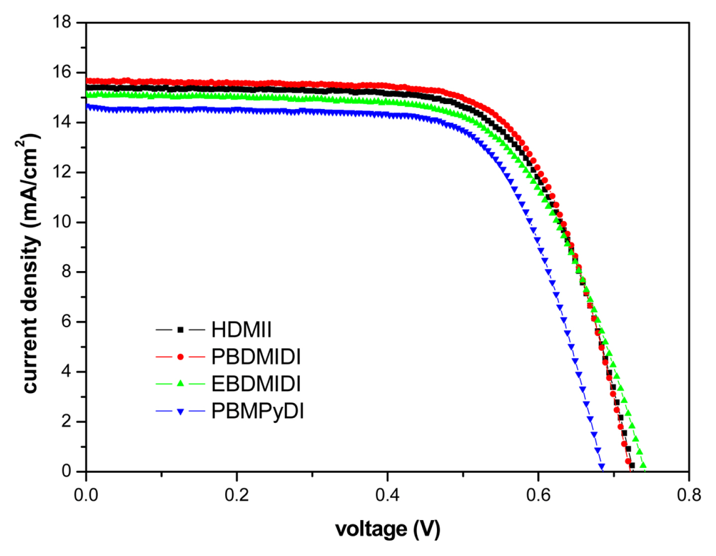
Current density-voltage (J–V) characteristics of the each devices with different ionic salt in acetonitrile HDMII (■), PBDMIDI (
 ), EBDMIDI (
 ), PBPyDI (
 ) measured under AM1.5G illumination from a calibrated solar simulator with irradiation intensity of 100 mW cm−2

Electrolyte ionic conductivity and photovoltaic parameters of the devices different salts dissolved in acetonitrile
Quite comparable efficiencies were obtained from electrolytes with synthesiszed dicationic iodide salts. Bulky cation, EBDMIDI, shows higher Voc than HDMII.
3.2 Dicationic Salts in Mixture of Acetonitrile (AcCN) and Propylene Carbonate (PC)
Synthesized dicationic salts did not well dissolve in acetonitrile. Dicationic salts might have stronger ionic bond than HDMII, therefore, these salts may need strong polar solvent. Propylene carbonate (PC) is an organic compound which is useful as a high polar solvent. Like previous experiment, 1-hexyl-2,3-dimethyl imidazolium iodide (HDMII) was used to prepare the reference electrolyte. 0.6 M 1-hexyl-2,3-dimethyl imidazolium iodide (HDMII), 0.1 M lithium iodide (LiI), 0.05 M iodine (I2), 0.1 M guanidinium thiocyanate and 0.5 M tert-butyl pyridine (TBP) dissolved in acetonitrile. However, synthesized ionic salts are used half amount of HDMII, 0.3 M concentrations, the other electrolytes compositions are the same of reference electrolyte. Acetonitrile and propylene carbonate solvent ratios were controlled. The Acetonitrile:PC solvents were mixed with different ratios, 7:3, 5:5, 3:7 and 0:1 (v/v). Fig. 2 and Table 3 show J-V characteristics of the cells with each electrolyte, photovoltaic parameters, respectively. In case of HDMII, HDMII with 7:3 (AcCN:PC) volume ratio solvent has the best efficiency compared with other ratios, but it did not reach the efficiency of the cell with only acetonitrile solvent. There is a rough tendency. When PC ratio increasing, the series resistance was also increased. The increased series resistance caused a low FFs. Therefore, the higher concentrations of PC there are, the poorer efficiencies were observed. The reason why higher concentration of PC solvent has poor efficiency is due to high viscosity of PC. Except PBPyDI, in most cases synthesized materials have higher Voc than HDMII. Owing to the existence of bulky dications on TiO2 photoelectrode surface, these bulky dications prohibited Li+ ion from affecting on conduction band of TiO2. Dicationic salts are available on the surface, occupy a much larger area than Li+ ions. Therefore, bulker cations on the TiO2 surface relieved lowering of the conduction band edge by Li+ ions [11].
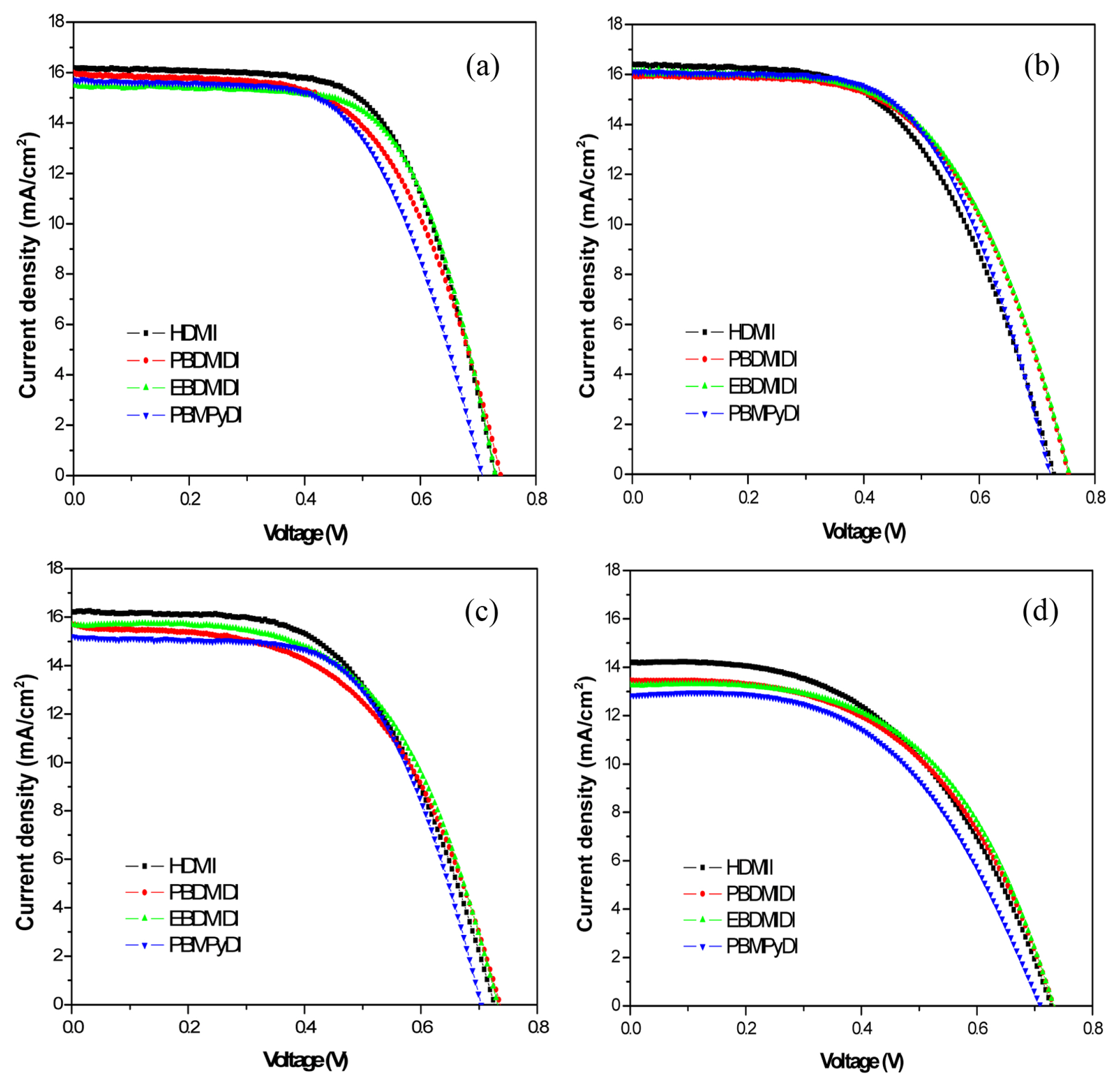
Current density-voltage (J–V) characteristics of the each devices with different ionic salt HDMII (■), PBDMIDI (
), EBDMIDI (
), PBPyDI (
) with different ratios of solvent (a) AcCN:PC=7:3, (b) AcCN:PC=5:5, (c) AcCN:PC=3:7, (d) PC, (v/v) measured under AM1.5G illumination from a calibrated solar simulator with irradiation intensity of 100 mW cm−2

Photovoltaic parameters of the devices different salts dissolved in different acetonitrile (AcCN):propylene carbonate (PC) volume ratios.
When 7:3 (AcCN:PC) volume ratio solvent was used, PBDMIDI electrolyte has the efficiency among different solvents with a good FF. Likewise, EBDMIDI and PBPyDI electrolytes were observed similar tendencies. While PC concentration was increasing, synthesized materials well dissolved, which did not have connection between solubility and efficiency. Increasing PC concentration, one of photovoltaic device characteristics, Jsc and FF were dropped. Both Jsc and FF are influenced by the ionic conductivity of electrolyte, because low conductivity causes rate determining of charge transportation and increasing the series resistance [12]. Ionic conductivity directly related by viscosity of electrolyte [13].
3.3 Dicationic Salts in Mixture of Acetonitrile (AcCN) and Ethylene Carbonate (EC)
Synthesized dicationic salts did not well dissolve in acetonitrile. Because dicationic salts may have stronger ionic bond than HDMII, these salts may need strong polar solvent. Ethylene carbonate (EC) is used as a polar solvent with a molecular dipole moment of 4.9 D [14], only 0.1 D lower than that of propylene carbonate. Like previous experiment, 1-hexyl-2,3-dimethyl imidazolium iodide (HDMII) was used to prepare the reference electrolyte. 0.6 M 1-hexyl-2,3-dimethyl imidazolium iodide (HDMII), 0.1 M lithium iodide (LiI), 0.05 M iodine (I2), 0.1 M guanidinium thiocyanate and 0.5 M tert-butyl pyridine (TBP) dissolved in various ratio of solvents. However, synthesized ionic salts are used half amount of HDMII, 0.3 M concentrations, the other electrolytes compositions are the same of reference electrolyte. Acetonitrile and propylene carbonate solvent ratios were controlled. The Acetonitrile:EC solvents were mixed with different ratios, 1:0, 7:3, 5:5 and 3:7 (v/v). Because the melting point of ethylene carbonate is higher than room temperature, EC based solvent electrolyte wasn’t carried out. Fig. 3 and Table 4 show J-V characteristics of the cells with each electrolyte, photovoltaic parameters, respectively. Instead of using PC on electrolyte, Jsc did not observe significantly. PBDMIDI electrolyte had the highest efficiency in every composition of AcCN and EC mixture. The reason why PBDMIDI electrolyte cells have higher efficiencies than others is PBDMIDI electrolyte cells have slightly higher voltages and FFs than others. In case of EC, also except PBPyDI, synthesized dication salt electrolytes have higher Voc than HDMII. The reason is the same effect of bulky cation on TiO2 surface [11].
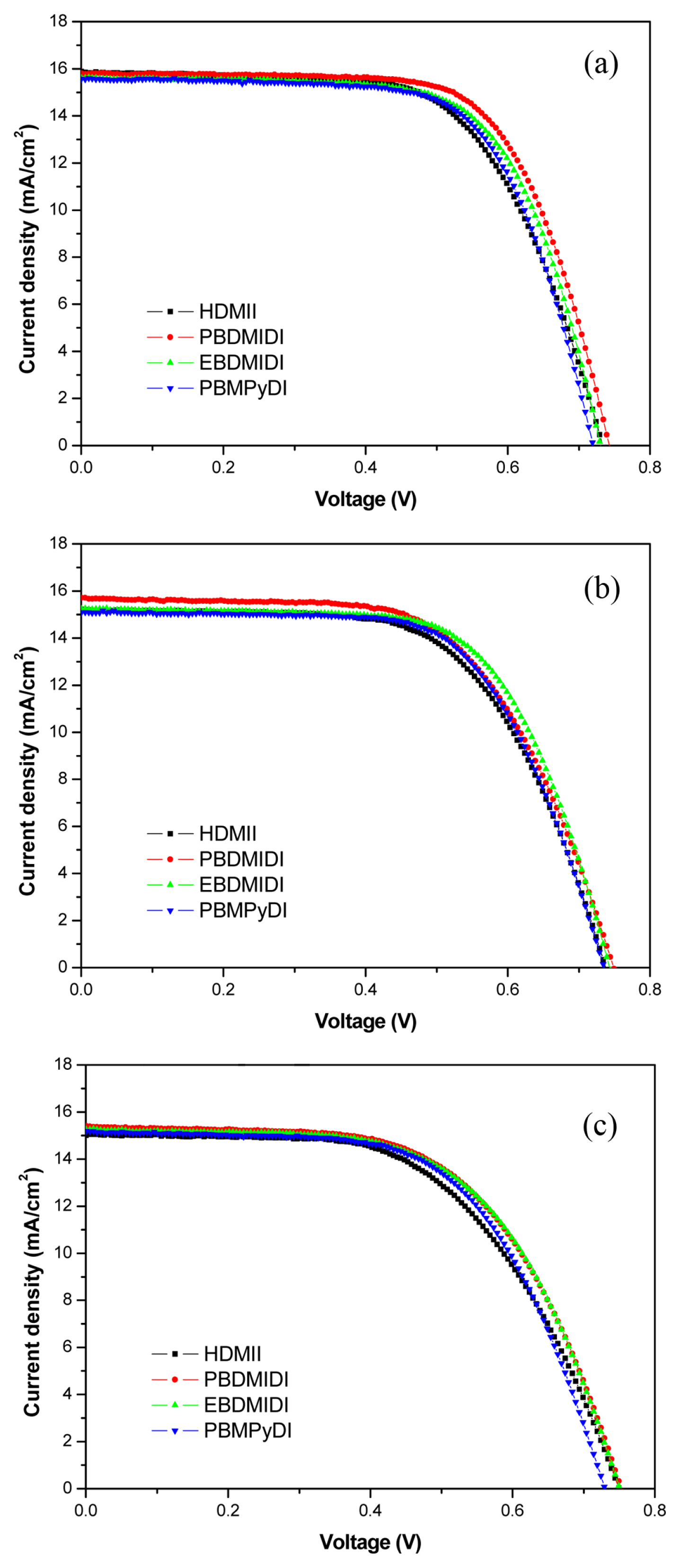
Current density-voltage (J–V) characteristics of the each devices with different ionic salt HDMII (■), PBDMIDI (
), EBDMIDI (
), PBPyDI (
) with different ratios of solvent (a) AcCN:EC=7:3, (b) AcCN:EC=5:5, (c) AcCN:EC=3:7 (v/v), measured under AM1.5G illumination from a calibrated solar simulator with irradiation intensity of 100 mW cm−2

Photovoltaic parameters of the devices different salts dissolved in different acetonitrile (AcCN):propylene carbonate (EC) volume ratios
3.4 Dicationic Salts in Mixture of γ-Butyrolactone and Ethylene Carbonate
In addition, mixed solvent of ethylene carbonate (EC) and γ-Butyrolactone (GBL) is used for high temperature stable electrolyte system. The boiling point of EC is 248°C. γ-Butyrolactone (GBL) is also a good candidate for solvent due to its high boiling point of 204°C. In addition, its dielectric constant of 42 and low viscosity of 1.7 mPas−1 are preferable characteristics for DSSC applications. A mixture of EC + GBL (30:70, v/v, chosen based on the phase diagram) has been employed as a stable solvent at high temperatures [15,16]. Like previous experiment, 1-hexyl-2,3-dimethyl imidazolium iodide (HDMII) was used to prepare the reference electrolyte. 0.6 M 1-hexyl-2,3-dimethyl imidazolium iodide (HDMII), 0.1 M lithium iodide (LiI), 0.05 M iodine (I2), 0.1 M guanidinium thiocyanate and 0.5 M tert-butyl pyridine (TBP) dissolved in EC + GBL (30:70, v/v). However, synthesized ionic salts are used half amount of HDMII, 0.3 M concentrations, the other electrolytes compositions are the same of reference electrolyte. Fig. 4 and Table 5 show J-V characteristics of the cells with each electrolyte, photovoltaic parameters, respectively. In this experiment, there are little different in Jsc and Voc. However, dicationic salts have better FFs than HDMII. It caused higher efficiencies. The best performance among them is EBDMIDI electrolyte which is 6.022% with 14.8 mA cm−2 (Jsc), 0.719 V (Voc) and 56.7% (FF).
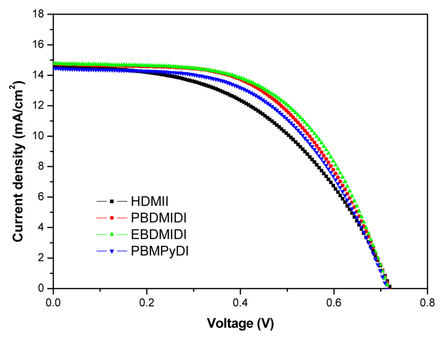
Current density-voltage (J–V) characteristics of the each devices with different ionic salt in GBL: EC=7:3 (v/v), HDMII (■), PBDMIDI (
), EBDMIDI (
), PBPyDI (
) measured under AM1.5G illumination from a calibrated solar simulator with irradiation intensity of 100 mW cm−2

Photovoltaic parameters of the devices different salts dissolved in acetonitrile(AcCN): γ-Butyrolactone=7:3 (v/v)
4. Conclusions
DSSCs are recognized as the promising device in the solar industry. These offer the prospective of very low-cost fabrication and present attractive features that facilitate market. In this work, it has been investigated to improve photovoltaic properties of DSSCs. New dicationic salts-based on ionic liquids were synthesized. Synthesized bulky cationic salts have been used in DSSC electrolyte systems as iodide sources with various solvent (mixture of acetonitrile, ethylene carbonate, propylene carbonate and γ-butyrolactone) systems. In this case, quite comparable results to the conventional imidazolium salts are obtained. For the experiments, dicationic salts with different structures of cation are applied. Possible reasons are suggested for Voc changes, Jsc drops and FF depending on composition of electrolyte solvent. Future directions of dicationic iodides should not only find better molecules than generally used one but also need to investigate mechanisms of dications behavior in the electrolyte. They are quite comparable to conventional mono-cationic device efficiencies with best efficiency of 7.96% with PBDMIDI.
Acknowledgement
This paper was supported by Konkuk University Researcher Fund in 2017. This work is supported by the Korea Institute of Energy Technology Evaluation and Planning (KETEP) and the Ministry of Trade, Industry and Energy (MOTIE, 20174010201490) and Korean Institute for Advancement of Technology(N0002431). This research was also supported by the National Research Foundation (NRF), which is funded by the Ministry of Science, ICT & Future Planning (2018M1A2A2058204).
Supporting Information
Additional electrochemical data and tables. This material is available from the author upon request.