1. Introduction
Since the ordered mesoporous materials based on the silica such as SBA-15 and MCM-41 were developed in 1990ŌĆÖs, the mesoporous materials have drawn great attraction due to the high surface area and narrow pore size distribution [1,2]. The silica based mesoporous materials have been usually fabricated by hydrolysis and condensation of silica precursor such as tetraethyl orthosilicate [3]. The porous structure can be easily controlled by changing the concentration of precursor or synthesis temperature [4ŌĆō6]. For the synthesis of ordered mesoporous non-silica materials, on the other hand, various strategies have been employed utilizing the diverse chemistry of non-silica materials [7ŌĆō10]. Especially, mesoporous transition metal oxides have shown promise in numerous fields such as energy storage, catalysis, adsorption, and separation, because they possess the high surface area and high redox properties [11ŌĆō17].
The preparation of the ordered mesoporous materials can be classified into hard template and soft template method by the type of template [18]. In case of the hard template method which is called as nanocasting or repeated templating method, the mesoporous materials such as anodic aluminum oxide (AAO), mesoporous carbon, and mesoporous silica have been generally used as templating agents [19ŌĆō21]. The advantage of hard template method is easy control of porous structure, relative and higher stability of template than the soft template method. Also, the synthesized materials should be stable in the base or acid solution such as NaOH and HF because these solutions are used to remove the template.
On the other hand, the soft template method generally utilizes the surfactant such as hexadecyltrimethylammonium chloride, Pluronic F127, or Pluronic P123 as a templating agent [22ŌĆō24]. Typically, the surfactant is added in relatively high concentration for the formation of micelles. This method is conducted under relatively mild conditions, and various ordered mesoporous materials can be synthesized by changing the experimental conditions. Also, when the soft template method is combined with electrodeposition, an ordered mesoporous structure can be fabricated at milder conditions because electrofabrication of mesoporous materials utilizes the micelles of adsorbed surfactants on the electrode surface [25].
The rapid development of industry has inspired vigorous research on energy storage. Among the various energy storage applications, supercapacitors have been attracting attention because of their high specific power density. Generally, a supercapacitor has hundreds of times power density of conventional secondary batteries [26]. Therefore, since the 1990s, supercapacitors have begun to attract attention as a means to improve the power of electric vehicles [27].
Supercapacitors are typically divided into two typesŌĆö electric double layer capacitors (EDLCs) and pseudocapacitors. EDLCs have high power density and a long-life cycle because the charge accumulates on the electrode surface by electrostatic force [28]. Therefore, the high surface area of the electrode and the contact between electrode and electrolyte are crucial for these supercapacitors. In contrast, the pseudocapacitor is based on a faradaic charge storage mechanism such as a surface redox reaction. The energy density of this type of supercapacitor is higher than that of EDLCs. Generally, transition metal oxides have been used as the electrode material due to high redox properties [29ŌĆō32]. Among the various transition metal oxides, manganese oxide is one of the promising materials due to its high abundance, low cost, eco-friendliness, and excellent redox properties [33].
In this work, highly ordered mesoporous manganese oxide (Mn2O3) films were prepared by electrodeposition onto indium tin oxide coated (ITO) glass in the presence of sodium dodecyl sulfate (SDS) and ethylene glycol (EG) which was used as a templating and structure stabilizer, respectively. The manganese oxide films synthesized with surfactant exhibited a highly mesoporous structure with well-ordered interspacing framework. The unique porous structure provides a more favorable diffusion path for mass transfer and excellent ionic conductivity. The Mn2O3 prepared with SDS and EG displayed an outstanding capacitance of 72.04 F gŌłÆ1, which outperform nonporous Mn2O3 (32.13 F gŌłÆ1) at a scan rate of 10 mV sŌłÆ1. These results were mainly ascribed to the well-ordered mesoporous structure and high surface area.
2. Experimental
2.1. Electrodeposition of mesoporous manganese oxide films
To electrodeposit the mesoporous manganese oxide, an electrolyte composed of 6 mM sodium dodecyl sulfate (SDS), 6 mM ethylene glycol (EG) and 10 mM manganese nitrate (Mn(NO3)2) in 100 mL of deionized (DI) water was prepared. Then, the mixture was vigorously stirred at 40┬░C for 30 min. All electrodeposition of manganese hydroxide films was performed at 70┬░C on indium tin oxide (ITO)-coated glass under constant potential (ŌłÆ1.6 V vs. Ag/AgCl/KCl (3 M)) in a standard three-electrode system with a Pt mesh and Ag/AgCl/KCl (3 M) as counter electrode and reference electrode, respectively. After deposition, the working electrodes were washed with ethanol several times and the heat treatment was performed at 200┬░C for 3 h. Finally, to remove the remaining surfactant, the synthesized electrodes were immersed in ethanol for 18 h. The synthesized sample was denoted as Mn2O3-SDS+EG. For comparison, manganese oxide films were also deposited without EG and SDS or with only SDS. The films were denoted as pristine-Mn2O3 and Mn2O3-SDS, respectively.
2.2. Physicochemical and electrochemical characterizations of mesoporous manganese oxide films
The porous structure was characterized using small-angle X-ray diffraction (SAXRD; RIGAKU, D/MAX 2200V/PC, Cu K╬▒ (1.54 ├ģ) X-ray irradiation source) and transmission electron microscopy (TEM; Philips, CM200). The oxidation states of manganese oxide were obtained via X-ray photoelectron spectroscopy (XPS; Thermo scientific, KAlpha).
Electrochemical properties such as the Tafel plot and cyclic voltammetry (CV) were measured using a three-electrode system with a Pt mesh and Ag/AgCl/ KCl (3 M) as the counter electrode and reference electrode, respectively. The Tafel plots was measured over a potential range of ŌłÆ1.2 V to ŌłÆ1.8 V vs. Ag/AgCl with a scan rate of 10 mV sŌłÆ1 to study the influence of the surfactants and additives on electro-deposition. CV for the measurement of capacitance was performed in a 0.5 M Na2SO4 solution for a sweep between 0 and 0.8 V vs. Ag/AgCl.
3. Results and Discussion
3.1. Cathodic deposition of manganese hydroxide
The mesoporous manganese oxide film was prepared by following two steps. In the first step, manganese hydroxide was cathodically electrodeposited using an aqueous solution with nitrate ions according to following reactions [34]:
Finally, the manganese oxide was synthesized on the ITO glass by heat treatment at 200┬░C for 3 h.
For the synthesis of manganese oxide, tree kinds of electrolytes were used; 1) without surfactant (pristine-Mn2O3), 2) with only SDS (Mn2O3-SDS), and 3) with a mixture of SDS and EG (Mn2O3-SDS+EG). To investigate the influence of the surfactants on electrodeposition, the Tafel slopes for three different electrolytes were investigated in the potential range from ŌłÆ1.2 to ŌłÆ1.8 V (vs. Ag/AgCl/KCl (3 M)). As shown in Fig. 1, a similar plateau was observed for the three electrolytes, and the Tafel slopes of all electrolytes were calculated to be about 145 mV decŌłÆ1. Therefore, it could be concluded that the electrodeposition reaction was identical in all of the electrolytes, and there was no serious side reaction with the addition of surfactants.
3.2. Physicochemical characterization of the synthesized manganese oxide
The oxidation states of the synthesized manganese oxide films after calcination at 200┬░C were evaluated by XPS. The binding energies obtained from XPS analysis were aligned by referencing the C 1s peak to 284.8 eV. As shown in Fig. 2, the Mn 3s spectra for all samples exhibited a spin energy separation of 5.6 eV regardless of the electrolyte. The synthesized manganese oxides after heat treatment at 200┬░C were confirmed to be Mn2O3, which was consistent with the XPS spectra reported by H. Xia et al. [35]. Based on the Tafel slope and XPS results, it was confirmed that the surfactant (SDS) and additive (EG) used in the synthesis of the mesoporous structure did not affect the formation of the manganese oxide films.
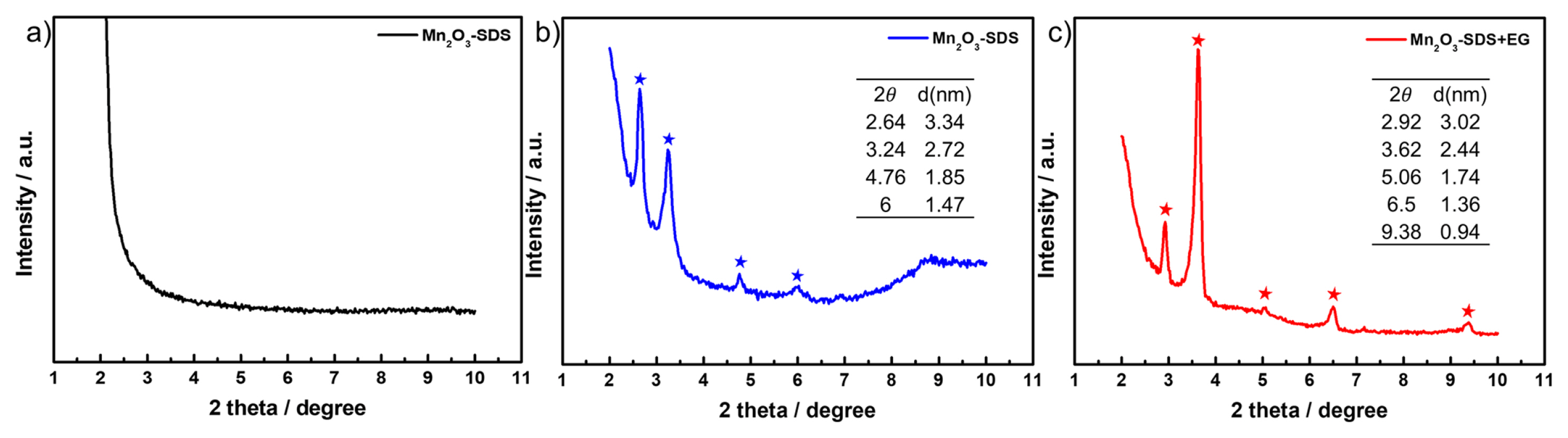
Small-angle X-ray diffraction (SAXRD) was used as a general tool to confirm the existence of an ordered mesoporous structure. Fig. 3 shows the SAXRD spectra of the manganese oxide films synthesized from three different electrolytes. The measurements were carried out between 2┬░ and 10┬░ at a scan rate of 0.3┬░ minŌłÆ1. The inter-pore distance of the deposited films was calculated based on the following BraggŌĆÖs law:
where n is a positive integer, ╬╗ is the wavelength of the X-ray (Cu K╬▒ = 1.5406 ├ģ), d is the inter-pore distance (in other words, the center-to-center distance between neighboring pores), and ╬Ė is BraggŌĆÖs angle. In the case of pristine-Mn2O3 which was synthesized without surfactant, no SAXRD peaks were observed, which indicated the absence of an ordered mesoporous structure. On the other hand, Mn2O3-SDS showed peaks at 2.64┬░, 3.24┬░, 4.76┬░, and 6┬░, corresponding to d-spacings of 3.34 nm, 2.72 nm, 1.85 nm, and 1.47 nm, respectively. Similarly, Mn2O3-SDS+EG films exhibited several peaks at 2.92┬░, 3.62┬░, 5.06┬░, and 6.5┬░, which were assignable to 3.02 nm, 2.44 nm, 1.74 nm, and 1.36 nm, respectively. These diffraction patterns demonstrated that the electrodeposited Mn2O3 displayed a highly ordered mesoporous structure, expecting enhanced electrochemical performance for a supercapacitor.
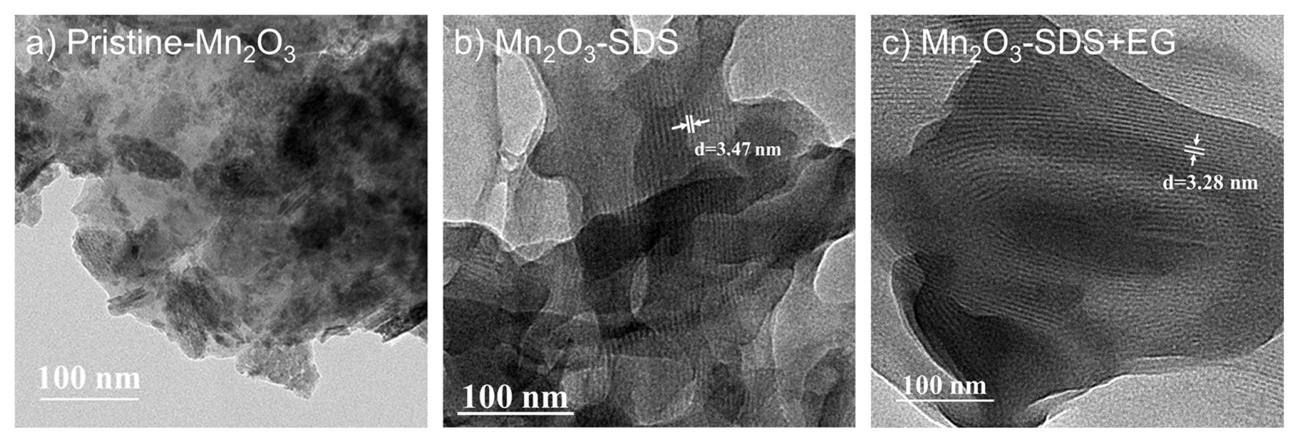
TEM images of the deposited manganese oxide films prepared with surfactants are shown in Fig. 4. Compared with featureless and dense structure of manganese oxide fabricated without surfactant (Fig. 4a), a highly ordered mesoporous structure was clearly observed in the manganese oxide films electrodeposited with surfactants as a templating agent. This ordered mesoporous structure could be very helpful in increasing the accessible electrochemical surface area. The inter-pore distance was estimated to be 2.5ŌĆō3.5 nm from the TEM images in Fig. 4, which was consistent with the small-angle XRD results. The highly ordered mesoporous structures synthesized with surfactants were thus confirmed using SAXRD and TEM. It has been known that EG can modify the construction of micelle structure of surfactant, leading to formation of rod-like array. Tan et al. [36] fabricated the two-dimensional mesoporous nickel hydroxide films by electrochemical deposition in dilute surfactant solutions in the presence of EG. In the solutions, EG gradually enlarges the spherical micelle volume of SDS as an expander, resulting in modification of micelle shape from the sphere to rod-like hexagonal structure. The unique mesoporous structure derived from the stable cylinder micelles can provide a high specific surface area, pore volume and a uniform mesopore size distribution, thus expecting the enhanced specific capacitance.
3.3. Electrochemical properties of ordered mesoporous manganese oxide
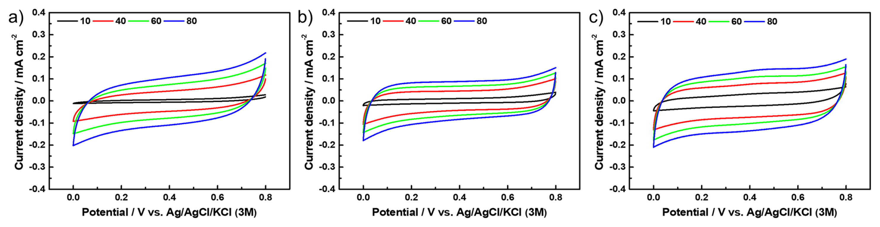
To investigate the electrochemical properties of the ordered mesoporous manganese oxides, cyclic voltammetry (CV) was conducted at scan rates of 10, 40, 60, 80, 100, and 200 mV sŌłÆ1 in the potential range of 0ŌĆō0.8 V using a 0.5 M Na2SO4 aqueous solution. Because all samples were electrodeposited at the identical conditions (at ŌłÆ1.6 V vs. Ag/AgCl/KCl (3 M) until reaching 200 mC) and the currents were almost similar as confirmed from Tafel slope measurement in Fig. 1, the deposited amounts of manganese oxide in each film was almost same. The deposited amount of manganese oxide was calculated from the weight difference between bare electrode (ITO coated glass) and manganese oxide coated electrode using a micro balance. As shown in Fig. 5, all CV plots regardless of scan rate exhibited a roughly rectangular plateau with broad quasireversible redox peaks. In cases of ordered mesoporous manganese oxides, the areas of CV were much higher than that of the non-porous sample (pristine-Mn2O3). which was attributed to their high electrochemical surface area. These results indicated an increase in accessible sur face sites for supercapacitive behavior in the ordered mesoporous samples relative to the non-porous sample.
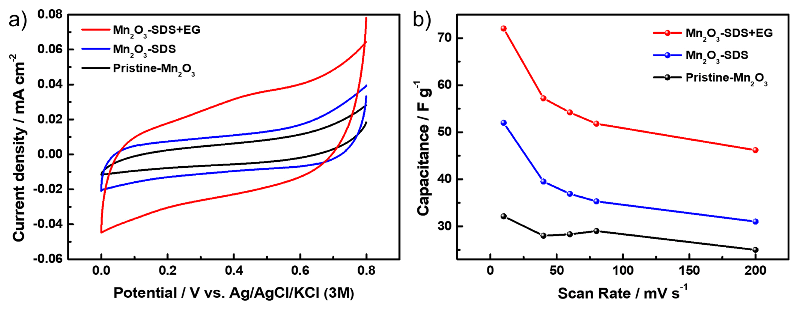
Fig. 6(a) shows the CV plots of each sample at 200 mV sŌłÆ1. Based on the CV plots, the specific capacitance of the deposited films was calculated using the following equation:
where I is the current, dt is the scan time interval, m is the sample mass, ╬öV is the potential range of each scan, and C is the specific capacitance of the synthesized electrode, respectively. The ordered mesoporous samples exhibited higher electrochemical performance than the non-porous sample, as shown in Fig. 6(a). The specific capacitances at 10 mV sŌłÆ1 were calculated to be 32.13 F gŌłÆ1, 51.25 F gŌłÆ1, and 72.04 F gŌłÆ1 for pristine-Mn2O3, Mn2O3-SDS, and Mn2O3-SDS+EG, respectively. These results indicate that the ordered mesoporous samples exhibited higher capacitance due to the higher electrochemically active surface area and well-developed porous structure. In addition, an ordered structure can increase the ionic mobility between the electrolyte and electrode surface by reducing the ionic diffusion path [37]. Interestingly, manganese oxide synthesized with a mixture of SDS and EG (Mn2O3-SDS+EG) exhibited much higher specific capacitance than manganese oxide synthesized with only SDS (Mn2O3-SDS) at all scan rates investigated. This result can be explained by the well-developed mesoporous structure with the addition of EG, as mentioned above. For all samples, the specific capacitance decreased with an increase of scan rate, as shown in Fig. 6(b). It is well known that a low scan rate allows sufficient electrolyte penetration into pores, leading to a more efficient contact between ions in electrolyte and the active materials. At high scan rates, in contrast, the high ion consumption rate (reaction rate) compared with the diffusion rate results in a low capacitance [38]. Among the synthesized samples, Mn2O3-SDS+EG exhibited the best electrochemical activity for a supercapacitor in the wide range of scan rate, which was attributed to an increase in the numerous active sites and enhanced accessibility of electrolyte caused by the unique mesoporous structure derived from cylindrical micelles.
4. Conclusions
In summary, we successfully synthesized highly ordered mesoporous manganese oxide by cathodic electrodeposition using SDS as a structure template. The fabricated ordered mesoporous structures exhibited inter-pore distance with a spacing of 2.5 to 3.5 nm. The synthesized porous structures were slightly changed by adding EG because these additives alter the interaction among SDS molecules and change the micellar structure. Based on Tafel and XPS results, the surfactant and additive had no effect on the electrodeposition of manganese oxide. With respect to electrochemical performance in supercapacitors, the ordered mesoporous samples exhibited higher capacitance and rate capability than the nonporous sample due to the high electrochemical surface area and increased ionic mobility. Among the synthesized samples, Mn2O3-SDS+EG showed the highest electrochemical performance for supercapacitors due to the increased active sites of the Mn2O3 with unique mesoporous structure derived from the addition of EG.