Investigation of Nanometals (Ni and Sn) in Platinum-Based Ternary Electrocatalysts for Ethanol Electro-oxidation in Membraneless Fuel Cells
Article information
Abstract
In the present work, Carbon supported Pt100, Pt80Sn20, Pt80Ni20 and Pt80Sn10Ni10 electrocatalysts with different atomic ratios were prepared by ethylene glycol-reduction method to study the electro-oxidation of ethanol in membraneless fuel cell. The electrocatalysts were characterized in terms of structure, morphology and composition by using XRD, TEM and EDX techniques. Transmission electron microscopy measurements revealed a decrease in the mean particle size of the catalysts for the ternary compositions. The electrocatalytic activities of Pt100/C, Pt80Sn20/C, Pt80Ni20/C and Pt80Sn10Ni10/C catalysts for ethanol oxidation in an acid medium were investigated by cyclic voltammetry (CV) and chronoamperometry (CA). The electrochemical results showed that addition of Ni to Pt/C and Pt–Sn/C catalysts significantly shifted the onset of ethanol and CO oxidations toward lower potentials. The single membraneless ethanol fuel cell performances of the Pt80Sn10Ni10/C, Pt80Sn20/C and Pt80Ni20/C anode catalysts were evaluated at room temperature. Among the catalysts investigated, the power density obtained for Pt80Sn10Ni10/C (37.77 mW/cm2 ) catalyst was higher than that of Pt80Sn20/C (22.89 mW/cm2 ) and Pt80Ni20/C (16.77 mW/ cm2 ), using 1.0 M ethanol + 0.5 M H2SO4 as anode feed and 0.1 M sodium percarbonate + 0.5 M H2SO4 as cathode feed.
1. Introduction
Fuel cells are electrochemical devices that directly convert chemical energy from a fuel oxidation reaction into electrical energy. Compared with other power sources, fuel cells have much higher energy efficiency, less CO2 emissions and other negative environmental impacts [1-3]. One class of microstructured power supply is microfluidic fuel cells or laminar flow-based fuel cells and membraneless fuel cells [1]. A microfluidic fuel cell defined as a fuel cell with fluid transport, reaction sites and electrode structures all confined to a microfluidic channel. This type of fuel cell operates without a physical barrier, such as a membrane to separate the anode and the cathode, and can use both metallic and biological catalysts. For a most typical architecture of microfluidic fuel cell, it operates in a co-laminar flow which is able to delay convective mixing of fuel and oxidant [1,2]. Microfluidic membraneless fuel cells avoid several issues associated with polymer electrolyte membrane-based fuel cells such as humidification, membrane degradation, water management, and fuel crossover. Moreover, miniaturization of membraneless fuel cells has drawn significant interest because of their potential advantages, including compact design, high-energy conversion efficiency, low operating temperature, environmental-friendly emissions, and elimination of the moving parts [4]. Ethanol as a hydrogen-rich liquid for microfluidic fuel cells is a very promising regarding its high energy density, non-toxicity, renewability, large-scale production from biomass, and easy storage and transportation [5]. This fuel is renewable, and its complete oxidation to CO2 and H2O produces a high yield of 12 electrons/molecule. Until date, microfluidic fuel cells, which operate at lower temperatures, have been based on platinum catalysts dispersed on carbon; however, ethanol electro-oxidation (EOR) on pure Pt does not display good catalytic activity due to poisoning of its active sites by intermediates generated from the reactions occurring in parallel with the oxidation of ethanol, which utilizes overpotential for oxidation of the target fuel [6,7]. Considerable efforts have been directed toward the development of effective electrocatalysts that can oxidize ethanol at lower potentials [8-10]. For example, alloys of Pt with other elements such as Ru, Rh, Ir, Mo, W, Sn, and Ni have been frequently studied as co-catalysts to minimize the effect of Pt poisoning with CO and other byproducts, thereby improving the catalytic activity [11-16].
Numerous investigations have reported that the Pt-Sn composition displays excellent activity for the oxidation of ethanol. Purgato et al. [17] investigated the introduction of different ratios of Sn into Pt catalysts prepared by the Pechini method, concluding that Sn enhances the catalytic activity of Pt. Neto et al. [7] have shown that the addition of Sn contributes to the formation of a more selective catalyst for the oxidation of ethanol. Song et al. [18] verified that the Pt–Sn catalyst presents greater selectivity for the oxidation of this alcohol compared with Pt alone via gas chromatography. Nevertheless, most of the products formed in the presence of Pt-Sn contains C-C bonds. Therefore, it is mandatory that the activity of the Pt-Sn/C catalyst is enhanced by the addition of a third element, such that the dehydrogenation reaction can be improved and the C-C bond can be cleaved during the oxidation of ethanol. The main advantage of the introduction of the third metal is the reduction of the oxidation potential of small organic molecules, coupled with the increase in the current density. The enhanced activity of the ternary catalyst is due to the promoting effect of the second or third elements added to Pt. Among the number of ternary compositions tested, Pt-Sn-M (M = Ni, Ir and Rh) has been repeatedly reported to enhance the catalytic activity for EOR in direct ethanol fuel cells (DEFCs) [19]. Pt-Sn-M has also been used in the microfluidic membraneless fuel cell system to improve the catalytic activity of EOR. In the present study, we evaluated the catalytic activity for the EOR reaction by incorporating a third metal Ni to the Pt–Sn catalyst on a carbon support in MLEFC. The performance of the Pt-Sn-Ni/C catalyst was compared with that of the Pt-Sn/C and Pt-Ni/C catalysts obtained by the alcohol-reduction method.
2. Experimental
2.1 Material
The metal precursors used for the preparation of electrocatalysts were H2PtCl6.6H2O (from Aldrich), SnCl2.2H2O (from Alfa Aesar), and NiCl2.6H2O (from Aldrich). Vulcan XC-72R carbon black (from Cabot Corp.,) was used as a support for the catalysts. Graphite plates (3-cm long and 1-cm wide from E-TEK) were used as substrates for the catalyst to prepare the electrodes. Polytetrafluoroethylene (PTFE) (6%; Aldrich) dispersion was used to prepare the catalyst slurry. Ethylene glycol (Merck) was used as the solvent and reduction agent. Ethanol (Merck), sodium percarbonate (Riedel), and sulphuric acid (H2SO4; Merck) were used as the fuel, oxidant, and electrolyte for electrochemical analysis, respectively. All the chemicals were of analytical grade. Pt/C (40 wt%; E-TEK) was used as the cathode catalyst.
2.2 Catalyst preparation
Carbon-supported ternary Pt-Sn-Ni catalysts with different atomic ratios were synthesized by the alcohol-reduction process [20]. Initially, the precursors were suspended in ethylene glycol and water (75/25 v/v), followed by the addition of carbon support. The resulting mixtures were treated in an ultrasound bath and were refluxed for 3 h under the open atmosphere. Then, the solution was made alkaline (adjusted to pH 12) and heated at 140℃ for 3 h under agitation to enable reduction of the metal. Finally, the precipitate was collected by filtration, washed with deionized (DI) water, and dried at 70℃ for 2 h. For comparison purpose, the monometallic Pt/C and bimetallic Pt-Sn/C and Pt-Ni/C catalysts were synthesized under the same conditions. The electrocatalytic mixtures and the atomic ratios were Pt100/C, Pt80Sn20/C, Pt80Ni20/C, and Pt80Sn10Ni10/C. The nominal loading of metals in the electrocatalysts was 40% wt and the remaining was 60%wt carbon.
2.3 Physical characterization
The morphology, microstructure, and elemental composition of catalysts were investigated by transmission electron microscopy (TEM) and energy-dispersive X-ray (EDX) analysis under the Philips CM 120 microscope/EDX analyzer equipped with a LaF6 filament. The particle size distribution and the mean particle size were also evaluated under TEM. The crystal structure of the synthesized electrocatalysts was characterized by powder X-ray diffraction (XRD) by using the Rigaku multiflex diffractometer (model RU-200 B) equipped with a Cu-Kα1 radiation source (λKα1= 1.5406 Å) operating at the room temperature. The tube current was 40 mA, with a tube voltage of 40 kV. The 2θ angular regions between 20° and 90° were recorded at a scan rate of 5° min−1. The mean particle size analyzed by TEM was verified by determining the crystallite size from the XRD pattern by using the Scherrer formula. Pt (220) diffraction peak was selected to calculate the crystallite size and lattice parameter of platinum.
According to the Scherrer’s equation [21]

Where, d is the average crystallite size, θmax is the angle at the position of the peak maximum, β2θ is the width of the peak (in radians), 0.9 is the shape factor for spherical crystallite, and λKα1 is the wavelength of the X-rays used. The lattice parameters of the catalysts were estimated according to Equation 2 [21]:
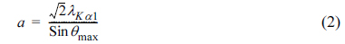
Where, a is the lattice parameter (nm) and all other symbols have the same meanings as in Equation 1 [22].
2.4 Electrochemical measurement
Electrochemical studies of the electrocatalysts were performed by using the thin porous coating technique [23]. All electrochemical measurements were performed on an electrochemical workstation (model CHI6650; CH Instruments, USA) interfaced with a personal computer using the CHI software at the room temperature. A common three-electrode electrochemical cell based on the cyclic voltammetry (CV) and chronoamperometry (CA) techniques for the measurements. Catalyst-coated glassy carbon electrode (GCE; 3-mm diameter and 0.071 cm2 of electrode area, CHI, USA) was used as the working electrode and platinum foil was used as the counter electrode. Ag/AgCl in saturated KCl was used as the reference electrode. The working electrode was prepared by applying the catalyst ink composed of 20 mg of the electrocatalysts in a solution of 50-mL water containing three drops of 6% PTFE suspension. The resulting mixture was treated in an ultrasound bath for 10 min to obtain a uniform dispersion. The catalyst slurry was then drop-cast on to a glassy carbon electrode and allowed to dry at 100℃ for 30 min. For assessing the electrocatalytic activity of the working electrode, CV was obtained in 1.0 M ethanol and 0.5 M H2SO4 solution with a scan rate of 50 mV s−1. For the durability test, the chronoamperometric experiments were conducted at 0.1 V for 3000 s in the same electrolyte. Before each measurement, the solution was purged with high-purity nitrogen gas for at least 30 min to ensure oxygen-free measurements.
2.5 Single cell test
In the present study, we fabricated the membraneless ethanol fuel cell (MLEFC) by using a laminar flow-based fuel cell configuration [4,24-25]. In this MLEFC, ethanol was used as a fuel, sodium percarbonate as an oxidant, and H2SO4 as an electrolyte. Ethanol is considered as one of the most promising combustible materials used in microfluidic fuel cells, because of its high-energy density, low toxicity, large scale production from biomass, easy storage and transportation. Sodium percarbonate is a true peroxo salt and is a convenient source of hydrogen peroxide [24,25].

The sodium percarbonate fuel cell is unique from previous fuel cells using H2O2, as mentioned in our earlier study sodium percarbonate can be used as not only as an oxidant but also as a reductant.
The MLEFC has some advantages, such as sodium percarbonate is a cheap, non-toxic, large scale industrial chemical used primarily in detergents and as a mild oxidant [24]. The cell being more environmentally friendly than the other fuel cells and the sodium percarbonate can be handled more simply than hydrogen, as it is well known fact that sodium percarbonate solution is a widespread safe disinfectant. The byproduct is completely innocuous and this stable and easily handled crystalline substance is used as oxidant in MLEFC.
In MLEFC, the aqueous fuel and oxidant streams flow in parallel in a single microchannel with the anode and cathode on the opposing sidewalls (Fig. 1). Graphite plates of 1-cm thickness served as the current collectors and catalyst support structures. The different anode and cathode catalysts were coated onto the graphite plates. For a single cell, the anode catalysts with different atomic ratios were prepared as follows: the catalyst ink was prepared by mixing the required quantity of catalyst with a solution of 50 mL water containing three drops of 6% PTFE dispersion in an ultrasonic bath for 10 min to obtain a uniform dispersion. The catalyst slurry was then spread onto the graphite plate by brushing, followed by drying at 100℃ for 30 min to obtain the anode and cathode electrodes. The catalysts tested on the anode side were Pt100/C, Pt80Sn20/C, Pt80Ni20/C, and Pt80Sn10Ni10/C with a catalyst loading 2 mg/cm2 . On the cathode side, Pt100/C with catalyst loading 2 mg/cm2 was used in all the experiments. The two catalyst-coated graphite plates were aligned to form a channel with 0.1 cm electrode-to-electrode distance (width), a 3 cm length, and a 0.1 cm height. The anolyte (fuel and electrolyte) and catholyte (oxidant and electrolyte) streams flow in a laminar fashion over the anode and cathode, respectively. The electrode area along a microchannel wall between the inlets and the outlet (3 cm long and 0.1 cm wide) was used as the geometric surface area of the electrodes in this study (0.3 cm2 ). The design has been described in detail elsewhere [1,27]. The anolyte used in the anode side was 1.0 M ethanol + 0.5 M H2SO4 and the catholyte used in the cathode side was 0.1 M percarbonate + 0.5 M H2SO4. The flow rate of each of the streams was 0.3 mL min−1 (total flow rate of 0.6 mL min−1). The MLEFC was operated at the room temperature. The current-voltage characteristics of MLEFC were measured on an electrochemical workstation and the data was verified by using a multi-meter (MAS-TECH® MAS830L).

Schematic of the E-shaped membraneless laminar flow-based fuel cell with graphite plates molded with poly(dimethylsiloxane) (PDMS) and sealed with poly (methylmethacrylate) (PMMA).
3. Results and Discussions
3.1 Physical characterization
3.1.1 X-ray diffraction (XRD)
XRD patterns revealed the bulk structure of the catalyst and its support. Fig. 2 shows the XRD patterns of Pt 100 /C, Pt 80Sn20 /C, Pt 80Ni20 /C, and Pt80Sn10Ni10/C catalysts. The peak at 25-30° observed in all diffraction patterns of the carbon-supported catalysts is attributed to the (0 0 2) plane of the hexagonal structure of the Vulcan XC-72R carbon support [28]. The diffraction peaks at around 40°, 47°, 68°, and 82° are attributed to the Pt (1 1 1), (2 0 0), (2 2 0), and (3 1 1) crystalline planes, respectively, which represents the typical character of crystalline Pt with face-centered cubic (FCC) crystalline structure. In the case of Pt80Ni20/C and Pt80Sn10Ni10/C, the addition of Ni to Pt promoted a shift in the Pt-peaks to slightly higher 2θ values, indicating the formation of an alloy upon incorporation of Ni into the platinum structure [29]. No peaks related to the metallic Ni or its oxides were observed. Addition of Sn shifts the Pt-peaks from 40° and 68° to lower diffraction angle of 39° and 67° . The shift of the Pt-peaks to the lower angles reveals alloy formation between the angle Pt and Sn, which is caused by the incorporation of Sn in the fcc structure of Pt [30]. For the Pt80Sn20/C catalyst, two additional small diffraction peaks were observed at around 34° and 52° , which can be attributed to SnO2 with the (1 0 1) and (2 1 1) planes, respectively, as reported by Jiang et al. [31] The presence of a small amount of SnO2 in the vicinity of Pt nanoparticles can supply oxygen-containing species for the oxidation of adsorbed species from ethanol adsorption on the neighboring Pt sites, enhancing their catalytic activity for EO at lower potentials. Pt (2 2 0) was selected to calculate the particle size and the crystalline lattice parameters of Pt in order to avoid the disturbance of C and Sn, which have no peaks near this angle [32,33]. The lattice parameters and the average crystallite size of the catalysts obtained from the XRD patterns are listed under Table 1.
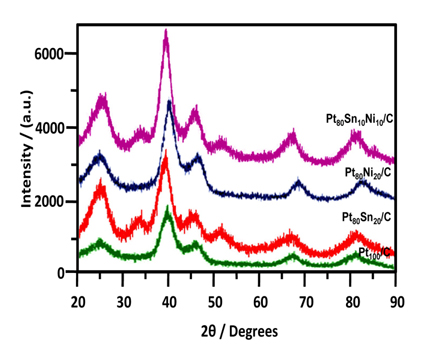
X-ray diffraction patterns of Pt100/C, Pt80Sn20/C, Pt80Ni20/C, and Pt80Sn10Ni10/C catalysts.
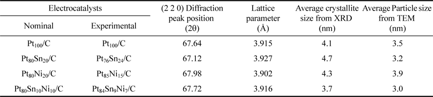
The results in Table 1 depict that the lattice parameter of the ternary Pt80Sn10Ni10/C catalyst were larger than those of Pt80Ni20/C and smaller than those of Pt80Sn20/C. This intermediate value of the lattice parameter of the Pt80Sn10Ni10/C catalyst indicates the partial substitution of Pt with Ni and Sn atoms, which can be introduced by shifting of the XRD peaks in the opposite directions [21]. The average crystallite sizes calculated by the Scherrer formula [20] at the peak position Pt (2 2 0) were approximately 4.7, 4.3, and 3.7 nm for Pt 80Sn20 /C, Pt 80Ni 20/C, and Pt80Sn10Ni10/C, respectively.
3.1.2 Transmission electron microscopy (TEM)
TEM images of the Pt100/C, Pt80Sn20/C, Pt80Ni20/C, and Pt80Sn10Ni10/C catalysts are shown in Fig. 3, together with the averaged value of the particle diameter distribution histograms. The micrographs of the electrocatalysts showed that all the catalysts had a good dispersion on the Vulcan XC-72R with a size in the same range and following a log-normal size distribution [34-36]. The average particle size for Pt100/C, Pt80Sn20/C, Pt80Ni20/C, and Pt80Sn10Ni10/C catalysts was 3-4 nm. In comparison to Pt80Sn20/C and Pt80Ni20/C, the mean particle size of Pt80Sn10Ni10/C was smaller. The variation in the mean particle size for these catalysts was quite similar in both the cases (TEM and XRD), indicating a good particle dispersion without formation of large particle aggregates (Table 1).
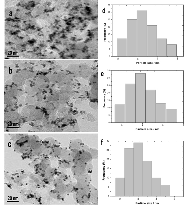
TEM images and particle size histograms of a and d) Pt80Sn20/C, b and e) Pt80Ni20/C, and c and f) Pt80Sn10Ni10/C catalysts.
3.1.3 EDX analysis
EDX analyses of all the Pt80Sn20/C, Pt80Ni20/C, and Pt80Sn10Ni10/C catalysts are shown in Fig. 4. Fig. 4a-c indicates the presence of Pt, Sn, and C; Pt, Ni, and C; and both the combinations of Pt, Sn, Ni, and C, respectively. The EDX results are shown in Table 1. The prepared catalysts had the desired elements with some variation in their composition. The EDX results of the binary Pt-Sn/C and Pt-Ni/C and the ternary Pt-Sn-Ni/C catalysts were extremely close to the nominal values, indicating that the metals were loaded onto the carbon support without any obvious loss.
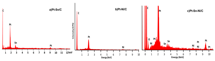
EDX spectra of a) Pt80Sn20/C, b) Pt80Ni20/C, and c) Pt80Sn10Ni10/C catalysts.
3.2 Electrochemical characterization
3.2.1 Cyclic voltammetry
Fig. 5a illustrates the CV curves of the Pt100/C, Pt80Sn20/C, Pt80Ni20/C, and Pt80Sn10Ni10/C catalysts, obtained in a half cell at a scan rate of 50 mVs1 between 0.05 and 0.8 V in the absence of ethanol. The curves stabilized after 20 cycles, and no severe changes were noted in the shape or size of the voltammograms during the entire period of measurements for all catalysts. As shown in Fig. 5a, the base CV of Pt100/C presents the characteristic features of polycrystalline Pt electrodes [37,38], regarding the hydrogen adsorption (1) and desorption (1’) signals (the hydrogen region), a double-layer region (2), surface oxide formation (3), and oxide reduction (3’) currents (the oxygen region). The voltammograms of the electrocatalysts did not display a well-defined hydrogen region between 0.05 and 0.4 V, as the catalyst’s features in this region are influenced by their surface composition [22]. Taking the Pt100/C composition as a reference, the binary Pt80Ni20/C catalyst showed a voltammetric charge similar to that of the pure Pt catalyst. However, a considerable increase in the voltammetric charge of Pt80Sn20/C and Pt80Sn10Ni10/C catalysts was noted observed in the double-layer region between 0.4 and 0.8 V, which may be attributed to the increase in the SnO2 species [39], as observed on the XRD images.
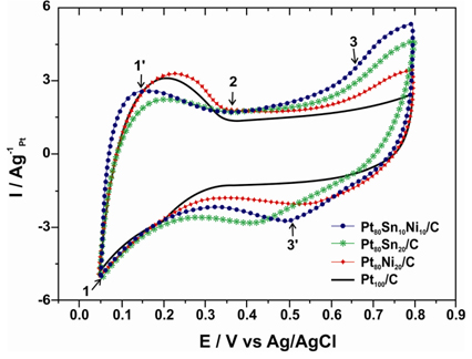
Cyclic voltammetry of Pt100/C, Pt80Sn20/C, Pt80Ni20/C, and Pt80Sn10Ni10/C electrocatalysts in 0.5 M H2SO4 at room temperature at a scan rate of 50 mV/s.
Fig. 5b shows the cyclic voltammograms of ethanol oxidation under acidic conditions (1.0 M C2H5OH and 0.5 M H2SO4) catalyzed by Pt100/C, Pt80Sn20/C, Pt80Ni20/C, and Pt80Sn10Ni10/C catalysts. All of the current values were normalized by the geometric surface area of the electrode used. The CV curves (Fig. 5b) depict the presence of a peak in the potential range of the positive sweep and another peak in the negative sweep. The peak in the positive sweep is associated with the ethanol oxidation, and the peak in the negative sweep is related to the oxidation of carbonaceous intermediate products from incomplete ethanol oxidation. Table 2 summarizes the CV results of Pt100/C, Pt80Sn20/C, Pt80Ni20/C, and Pt80Sn10Ni10/C electrocatalysts including the positive peak potentials and the corresponding peak current densities of EOR. The CV results show that pure Pt100/C catalysts (Fig. 5b) do not behave as an appropriate anode for EOR due to its poisoning by strongly adsorbed intermediates such as COads [40]. However, the introduction of Sn and Ni promotes the electrocatalytic activity. The EOR starts at approximately 0.3 V on the Pt80Sn20/C electrode, while the onset potential on Pt80Ni20/C was noted at 0.4 V vs. Ag/AgCl. This observation can be explained by the more pronounced oxophilic character of tin at low potentials in comparison with nickel [20,41-42]. Furthermore, the presence of both co-catalysts, Ni and Sn, significantly reduced the onset potential to approximately 0.2 V vs. Ag/AgCl and raised the current density at the Pt80Sn10Ni10/C electrocatalyst. The superior activity of the Pt80Sn10Ni10/C electrocatalyst can be attributed to the modification of electronic properties of platinum and to the presence of nickel oxide species resulting in a combination of electronic effect and bifunctional mechanism [43-45]. Again, the ternary compositions (Pt80Sn10Ni10/C) presented much higher current densities than the binary catalysts, indicating that the activity of the ternary electrocatalysts toward EOR was much better than that of the binary compositions.

3.2.2 Chronoamperometry
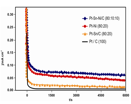
The Pt100/C, Pt80Sn20/C, Pt80Ni20/C, and Pt80Sn10Ni10/C electrocatalyst performances for etha-nol oxidation were studied by CA at 0.4 V vs Ag/AgCl for 2 h to evaluate both the electrocatalytic activity of the catalysts and the poisoning of the active surface under continuous operation conditions. Fig. 6 shows the representative chronoamperograms obtained for the different electrocatalysts whose current densities were normalized by Pt mass. During the first 5 min, a sharp decrease in the current density. Followed by relative stabilization was noted. This occurs because the active sites were initially free from the adsorbed/oxidized ethanol molecules. However, as the reaction proceeds, the adsorption rate of a new ethanol molecule depends on the availability of the catalyst active site. This reaction is metal-dependent and proceeds faster (high current density) in the case of metals with a good ability to oxidize the intermediate species responsible for poisoning of the catalytic sites (CO, CHx, CH3CHO, and CH3COOH) [46]. Thus, the surface becomes unstable, and the phenomena such as crystallization, segregation of the metal surface, and agglomeration of particles may occur to create new catalytic sites. The latter are quickly poisoned, thereby contributing to the continuous decrease in the current [21]. The compositions Pt100/C, Pt80Sn20/C, Pt80Ni20/C, and Pt80Sn10Ni10/C gave rise to extremely rapid rates of poisoning of the catalytic sites, resulting in a very low activity. However, ternary material (Pt80Sn10Ni10/C) had a good ability to overcome catalyst poisoning, thus furnishing a high current density [6].

Cyclic voltammetry of Pt100/C, Pt80Sn20/C, Pt80Ni20/C, and Pt80Sn10Ni10/C electrocatalysts in 0.5 M H2SO4 and 1.0 M ethanol at room temperature at a scan rate of 50 mV/s.
The ternary Pt80Sn10Ni10/C electrocatalysts demonstrated higher current than the binary Pt80Sn20/C and Pt80Ni20/C electrocatalysts. Higher current obtained for the ternary electrocatalysts may be explained by the operation of a beneficial synergistic effect between Sn and Ni, which may indicate an increase in the structural defects or roughness, making the ternary electrocatalysts better candidates for EOR. Furthermore, the addition of Ni to the Pt-Sn alloy electrocatalysts can lead to an increase in the surface oxophilic character, thus increasing the Sn-O bond strength and the acidity of the Sn-OH sites, favoring the bifunctional character of EOR [47]. The beneficial effect of Ni addition has been reported earlier for Pt-Sn/C and Pt-Ru/C catalysts. Indeed, significant improvements in ethanol and methanol oxidation were observed [48-50]. These observations suggest that the performance of Pt-Sn-Ni/C electrocatalysts depends greatly on its atomic ratios and its preparation.
3.3 Single cell performance
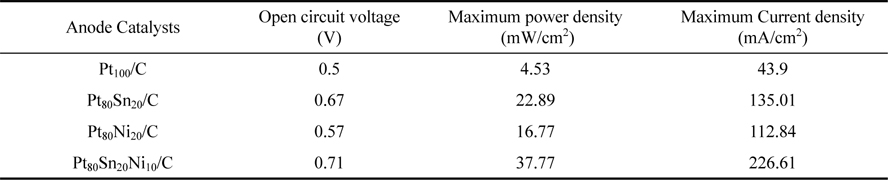
The Pt100/C, Pt80Sn20/C, Pt80Ni20/C, and Pt80Sn10Ni10/C catalysts were evaluated as anode catalysts for EOR by single MLEFC. The polarization and power density curves of different catalyst are presented in Fig. 7. When Pt100/C was used as the anode catalyst, the performance of MLEFC was found to be poor. The open-circuit potential (OCP) of Pt100/C was 0.5 V, which is far less than that of the reversible OCP (1.145 V) [16], which can be attributed mainly to the poor catalytic activity toward EOR. The results of MLEFC adopting to different catalysts are summarized in Table 3. When the current was normalized to the geometric area of a single cell, it was observed that the cell performance of the Pt80Sn10Ni10/C catalyst was better than that of other catalysts. In the low-current discharging region, the power drawn from a single cell was almost the same for all catalysts, except for Pt80Ni20/C and Pt100/C. However, as the voltage reached approximately 0.3 V, Pt80Sn10Ni10/C started drawing more current compared to others. The OCP for Pt80Sn20/C catalyst was 0.67 V lower than that for Pt80Sn10Ni10/C (0.71 V). In addition, a rapid initial fall in the cell voltage was noted for all catalysts, which was due to the slow initial EOR reaction at the electrode surface. After an initial drop of 0.5 V, the change in the slope of the polarization curve for Pt80Sn10Ni10/C decreased, and it started drawing more current. This event can be attributed to the more effective catalytic ability of Pt80Sn10Ni10/C, once the EOR reaction is initiated. Based on the peak power density drawn from a single cell, Pt80Sn10Ni10/C is the best anode catalyst with a peak power density value of 37.77 mW/cm2.
Chronoamperometry of Pt100/C, Pt80Sn20/C, Pt80Ni20/C, and Pt80Sn10Ni10/C electrocatalysts at the room temperature.
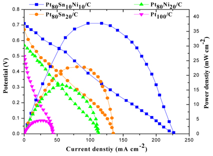
Polarization and power density curves of different catalyst at 2 mg cm−2 catalyst loading on the anode and cathode at the room temperature.
The addition of Sn clearly enhanced the EOR reaction as observed from the polarization curves that the electrocatalysts containing Sn showed higher open circuit voltage (OCV). Pt80Sn20/C (Sn 20 at.%) and Pt80Sn10Ni10/C (Sn 10 at.%) showed OCV of 0.67 V and 0.71 V, respectively, in comparison to Pt80Ni20/C and Pt100/C, which showed OCV of 0.57 V and 0.5 V, respectively. The comparison of both the bimetallic catalysts showed a peak power density of Pt80Sn20/C (22.89 mW/cm2), which was higher than that of Pt80Ni20/C (16.77 mW/cm2).
The addition of Ni is conducive to the breaking of C-C bonds in Pt80Sn10Ni10/C, and intensifies the further oxidation of the intermediates. This event may be due to the adsorption of the intermediates on the active sites of the catalysts. In the tri-metallic combinations of Pt, Sn, and Ni, the addition of Sn increases the cell performances. It can be observed that, for Pt80Ni20/C and Pt80Sn10Ni10/C combination containing 20 and 10 atomic ratios of Ni, the peak power densities were 16.77 and 37.77 mW/cm2 , respectively. This observation indicates that the presence of only a small amount of Sn in the PtSnNi/C catalyst aids in the EOR. Even under working conditions of the fuel cells, the best performance is achieved with lower Sn atomic ratios (near 10 wt%). Similar results were observed by Ribeiro et al. [51] for ethanol oxidation by using catalysts prepared by the Pechini-Adams modified method.
4. Conclusions
In this paper, we observed that the alcohol-reduction process could be effectively used for the preparation of Pt100/C, Pt80Sn20/C, Pt80Ni20/C, and Pt80Sn10Ni10/C eletrocatalysts for ethanol oxidation in H2SO4 solution. The X-ray diffractograms of the Pt– Ni/C electrocatalyst showed a typical fcc structure of the Pt alloys. The Pt-Sn/C and Pt-Sn-Ni/C electrocatalysts showed a typical fcc structure of platinum alloys in the presence of a separated SnO2 phase. The Pt metal was the predominant material in all the samples, with peaks attributed to the face-centered cubic (fcc) crystalline structure. TEM measurements revealed a decrease in the mean particle size of the catalysts for the ternary compositions, because the structural change was beneficial for the catalytic activity of the compositions. EDX analysis indicated that the experimental composition is in agreement with the nominal composition of the catalyst, which confirms the formation of Pt80Sn20/C, Pt80Ni20/C, and Pt80Sn10Ni10/C metal catalysts with the typical Pt crystalline structure and the formation of PtSn alloy. CV results showed that Pt80Sn10Ni10/C is more active in EOR than in other catalysts. The onset potential for this reaction was found to be 0.2 V vs. Ag/AgCl, which suggests that the activation occurs at the electrode surface by a ligand effect. CA results showed that the ternary Pt80Sn10Ni10/C catalysts gave higher current than the binary Pt80Sn20/C and Pt80Ni20/C catalysts at a steady condition. The enhanced ethanol oxidation activity by the ternary Pt80Sn10Ni10/C catalyst was mainly ascribed to the synergistic effect between Sn and Ni and to the smaller particle size. In this study, carbon-supported binary Pt80Sn20/C, Pt80Ni20/C, and ternary Pt80Sn10Ni10/C anode catalysts were successfully tested in a single membraneless fuel cell using 1.0 M ethanol as fuel and 0.1 M sodium percarbonate as the oxidant in the presence of 0.5 M H2SO4 as the electrolyte. Based on the peak power density drawn from a single cell, Pt80Sn10Ni10/C was found to be the best anode catalyst with a peak power density of 37.77 mW/cm2 among the tested catalysts. Further work is necessary to characterize the catalysts by using different surface analysis tech-niques and to conduct tests of these electrocatalysts in microfluidic membraneless fuel cells.
Acknowledgements
The financial support for this research from University Grants Commission (UGC), New Delhi, India through a Major Research Project 42-325/2013 (SR) is gratefully acknowledged.
References
E.R. Choban, L.J. Markoski, A. Wieckowski, and P.J.A. Kenis, J. Power Sources, 128, 54(2004).
Choban E.R., Markoski L.J., Wieckowski A., Kenis P.J.A.. J. Power Sources 2004;128:54. 10.1016/j.jpowsour.2003.11.052.E. Kjeang, N. Djilali, and D. Sinton, J. Power Sources, 186, 353(2009).
Kjeang E., Djilali N., Sinton D.. J. Power Sources 2009;186:353. 10.1016/j.jpowsour.2008.10.011.M.S. Whittingham, R.F. Savinell, and T.A. Zawodzinski, Chem. Rev., 104, 4243(2004).
Whittingham M.S., Savinell R.F., Zawodzinski T.A.. Chem. Rev. 2004;104:4243. 10.1021/cr020705e.A. Kowal, M. Li, M. Shao, K. Sasaki, M.B. Vukmirovic, J. Zhang, N. S. Marinkovic, P. Liu, A. I. Frenkel, and R. R. Adzic, Nature Mater., 8, 325(2009).
Kowal A., Li M., Shao M., Sasaki K., Vukmirovic M.B., Zhang J., Marinkovic N. S., Liu P., Frenkel A. I., Adzic R. R.. Nature Mater. 2009;8:325. 10.1038/nmat2359.J. Ribeiro, D.M. dos Anjos, J.-M. Leger, F. Hahn, P. Olivi, A.R. de Andrade, G. Tremiliso-Filho, and K.B. Kokoh, J. Appl. Electrochem., 38, 653(2008).
Ribeiro J., dos Anjos D.M., Leger J.-M., Hahn F., Olivi P., de Andrade A.R., Tremiliso-Filho G., Kokoh K.B.. J. Appl. Electrochem. 2008;38:653. 10.1007/s10800-008-9484-8.T.S. Almeida, L.M. Palma, C. Morais, K.B. Kokoh, and A.R. de Andrade, J. Electrochem. Soc., 160, F965(2013).
Almeida T.S., Palma L.M., Morais C., Kokoh K.B., de Andrade A.R.. J. Electrochem. Soc. 2013;160:F965. 10.1149/2.025309jes.A.O. Neto, R.R. Dias, M.M. Tusi, M. Linardi, and E.V. Spinace, J. Power Sources, 166, 87(2007).
Neto A.O., Dias R.R., Tusi M.M., Linardi M., Spinace E.V.. J. Power Sources 2007;166:87. 10.1016/j.jpowsour.2006.12.088.M.L. Calegaro, H.B. Suffredini, S.A.S. Machado, and L.A. Avaca, J. Power Sources, 156, 300(2006).
Calegaro M.L., Suffredini H.B., Machado S.A.S., Avaca L.A.. J. Power Sources 2006;156:300. 10.1016/j.jpowsour.2005.06.015.L. Jiang, G. Sun, Z. Zhou, W. Zhou, and Q. Xin, Catal. Today, 93-95, 665(2004).
Jiang L., Sun G., Zhou Z., Zhou W., Xin Q.. Catal. Today 2004;93-95:665. 10.1016/j.cattod.2004.06.029.M. Zhu, G. Sun, S. Yan, H. Li, and Q. Xin, Energy & Fuels, 23, 403(2009).
Zhu M., Sun G., Yan S., Li H., Xin Q.. Energy & Fuels 2009;23:403. 10.1021/ef800726b.C. Lamy, E.M. Belgsir, and J.-M. Léger, J. Appl. Electrochem., 31, 799(2001).
Lamy C., Belgsir E.M., Léger J.-M.. J. Appl. Electrochem. 2001;31:799. 10.1023/A:1017587310150.F. Wang, Y. Zheng, and Y. Guo, Fuel cells, 6, 1100(2010).
Wang F., Zheng Y., Guo Y.. Fuel cells 2010;6:1100.L. Jiang, G. Sun, S. Sun, J. Liu, S. Tang, H. Li, B. Zhou, and Q. Xin, Electrochim. Acta, 50, 5384(2005).
Jiang L., Sun G., Sun S., Liu J., Tang S., Li H., Zhou B., Xin Q.. Electrochim. Acta 2005;50:5384. 10.1016/j.electacta.2005.03.018.W.J. Zhou, W.Z. Li, S.Q. Song, Z.H. Zhou, L.H. Jiang, and G.Q. Sun, J. Power Sources, 131, 217(2004).
Zhou W.J., Li W.Z., Song S.Q., Zhou Z.H., Jiang L.H., Sun G.Q.. J. Power Sources 2004;131:217. 10.1016/j.jpowsour.2003.12.040.H. Bönnemann, W. Brijoux, R. Brinkmann, R. Fretzen, T. Joussen, R. Köppler, B. Korall, P. Neiteler, and J. Richter, J. Mol. Catal., 86, 129(1994).
Bönnemann H., Brijoux W., Brinkmann R., Fretzen R., Joussen T., Köppler R., Korall B., Neiteler P., Richter J.. J. Mol. Catal. 1994;86:129. 10.1016/0304-5102(93)E0148-A.E.M. Cunha, J. Ribeiro, K.B. Kokoh, and A. R. de Andrade, Int. J. Hydrogen Energy, 36, 11034(2011).
Cunha E.M., Ribeiro J., Kokoh K.B., de Andrade A. R.. Int. J. Hydrogen Energy 2011;36:11034. 10.1016/j.ijhydene.2011.06.011.F.L.S. Purgato, P. Olivi, J.-M. Léger, A.R. de Andrade, G. Tremiliosi- Filho, and E.R. Gonzalez, J. Electroanal.Chem., 628, 81(2009).
Purgato F.L.S., Olivi P., Léger J.-M., de Andrade A.R., Tremiliosi- Filho G., Gonzalez E.R.. J. Electroanal.Chem. 2009;628:81. 10.1016/j.jelechem.2009.01.010.E.M. Crabb, R. Marshall, and D. Thompsett, J. Electrochem. Soc., 147, 4440(2000).
Crabb E.M., Marshall R., Thompsett D.. J. Electrochem. Soc. 2000;147:4440. 10.1149/1.1394083.F. Colmati, E. Antolini, and E.R. Gonzalez, J. Alloys Compd., 456, 264(2008).
Colmati F., Antolini E., Gonzalez E.R.. J. Alloys Compd. 2008;456:264. 10.1016/j.jallcom.2007.02.015.E.V. Spinace’, M. Linardi, and A.O. Neto, Electrochem. Commun., 7, 365(2005).
Spinace’ E.V., Linardi M., Neto A.O.. Electrochem. Commun. 2005;7:365. 10.1016/j.elecom.2005.02.006.V. Radmiloviae, H.A. Gasteiger, and P.N. Ross Jr., J. Catal., 154, 98(1995).
Radmiloviae V., Gasteiger H.A., Jr. Ross P.N.. J. Catal. 1995;154:98. 10.1006/jcat.1995.1151.S. Beyhan, J.-M. Leger, and F. Kadýrgan, Appl. Catal., B: Environ., 130-131, 305(2013).
Beyhan S., Leger J.-M., Kadýrgan F.. Appl. Catal., B: Environ. 2013;130-131:305. 10.1016/j.apcatb.2012.11.007.F. Colmati, E. Antolini, and E.R. Gonzalez, Appl. Catal. B, 73, 106(2007).
Colmati F., Antolini E., Gonzalez E.R.. Appl. Catal. B 2007;73:106. 10.1016/j.apcatb.2006.06.013.K. Ponmani, S. Durga, M. Gowdhamamoorthi, S. Kiruthika, and B. Muthukumaran, Ionics, 20, 1579(2014).
Ponmani K., Durga S., Gowdhamamoorthi M., Kiruthika S., Muthukumaran B.. Ionics 2014;20:1579. 10.1007/s11581-014-1118-z.A. Arun, M. Gowdhamamoorthi, S. Kiruthika, and B. Muthukumaran, J. Electrochem. Soc., 161, F311(2014).
Arun A., Gowdhamamoorthi M., Kiruthika S., Muthukumaran B.. J. Electrochem. Soc. 2014;161:F311. 10.1149/2.067403jes.F.A. Cotton, and G. Wilkinson, Advanced inorganic chemistry, Wiley Interscience, New York, pp. 812(1988).
Cotton F.A., Wilkinson G.. Wiley Interscience. New York: 1988. p. 812.R.S. Jayashree, S.K. Yoon, F.R. Brushett, P.O. Lopez-Montesinos,D. Natarajan, L.J. Markoski, and P.J.A. Kenis, J. Power Sources, 195, 3569(2010).
Jayashree R.S., Yoon S.K., Brushett F.R., Lopez-Montesinos P.O., Natarajan D., Markoski L.J., Kenis P.J.A.. J. Power Sources 2010;195:3569. 10.1016/j.jpowsour.2009.12.029.J. Tayal, B. Rawat, and S. Basu, Int. J. Hydrogen Energy, 36, 14884(2011).
Tayal J., Rawat B., Basu S.. Int. J. Hydrogen Energy 2011;36:14884. 10.1016/j.ijhydene.2011.03.035.T.S. Almeida, K.B. Kokoh, and A.R. de Andrade, Int. J. Hydrogen Energy, 36, 3803(2011).
Almeida T.S., Kokoh K.B., de Andrade A.R.. Int. J. Hydrogen Energy 2011;36:3803. 10.1016/j.ijhydene.2010.12.066.A. Bonesi, W.E. Triaca, and A.M. Castro Luna, Port. Electrochim. Acta, 27, 193(2009).
Bonesi A., Triaca W.E., Castro Luna A.M.. Port. Electrochim. Acta 2009;27:193. 10.4152/pea.200903193.L. Jiang, L. Colmenares, Z. Jusys, G.Q. Sun, and R.J. Behm, Electrochim. Acta, 53, 377(2007).
Jiang L., Colmenares L., Jusys Z., Sun G.Q., Behm R.J.. Electrochim. Acta 2007;53:377. 10.1016/j.electacta.2007.01.047.S. Mukarjee, S. Srinivasan, M.P. Soriaga, and J. Mcrreen, J. Electrochem. Soc., 142, 1409(1995).
Mukarjee S., Srinivasan S., Soriaga M.P., Mcrreen J.. J. Electrochem. Soc. 1995;142:1409. 10.1149/1.2048590.C. Audo, J.F. Lambert, M. Che, and B. Didillon, Catal. Today, 65, 157(2001).
Audo C., Lambert J.F., Che M., Didillon B.. Catal. Today 2001;65:157. 10.1016/S0920-5861(00)00589-7.C.G. Granqvist, and R.A. Buhrman, J. Catal., 42, 477(1976).
Granqvist C.G., Buhrman R.A.. J. Catal. 1976;42:477. 10.1016/0021-9517(76)90125-1.C.G. Granqvist, and R.A. Buhrman, J. Appl. Phys., 47, 2200(1976).
Granqvist C.G., Buhrman R.A.. J. Appl. Phys. 1976;47:2200. 10.1063/1.322870.P. Ehrburger, and P.R. Walker Jr., J. Catal., 55, 63(1978).
Ehrburger P., Jr. Walker P.R.. J. Catal. 1978;55:63. 10.1016/0021-9517(78)90187-2.R. Woods, in: A.J. Bard (Ed.), Electroanalytical Chemistry, Marcel Dekker, New York (1976).
Woods R.. In : Bard A.J., ed. Electroanalytical Chemistry Marcel Dekker. New York: 1976.D.A.J. Rand, and R. Woods, J. Electroanal. Chem. Interfacial Electrochem., 36, 57(1972).
Rand D.A.J., Woods R.. J. Electroanal. Chem. Interfacial Electrochem. 1972;36:57. 10.1016/S0022-0728(72)80445-5.E.V. Spinace’, A.O. Neto, and M. Linardi, J. Power Sources, 129, 121(2004).
Spinace’ E.V., Neto A.O., Linardi M.. J. Power Sources 2004;129:121. 10.1016/j.jpowsour.2003.11.056.F. Vigier, C. Coutanceau, F. Hahn, E.M. Belgsir, and C. Lamy, J. Electroanal. Chem., 563, 81(2004).
Vigier F., Coutanceau C., Hahn F., Belgsir E.M., Lamy C.. J. Electroanal. Chem. 2004;563:81. 10.1016/j.jelechem.2003.08.019.A. Bonesi, G. Garaventa, W.E. Triaca, and A.M. Castro Luna, Int. J. Hydrogen Energy, 33, 3499(2008).
Bonesi A., Garaventa G., Triaca W.E., Castro Luna A.M.. Int. J. Hydrogen Energy 2008;33:3499. 10.1016/j.ijhydene.2007.12.056.A.R. Bonesi, M.S. Moreno, W.E. Triaca, and A.M. Castro Luna, Int. J. Hydrogen Energy, 35, 5999(2010).
Bonesi A.R., Moreno M.S., Triaca W.E., Castro Luna A.M.. Int. J. Hydrogen Energy 2010;35:5999. 10.1016/j.ijhydene.2009.12.093.J.-H. Choi, K.-W. Park, B.-K. Kwon, and Y.-E. Sung, J. Electrochem. Soc., 150, A973(2000).
Choi J.-H., Park K.-W., Kwon B.-K., Sung Y.-E.. J. Electrochem. Soc. 2000;150:A973–973.K.-W. Park, J.-H. Choi, B.-W. Kwon, S.-A. Lee, and Y.-E. Sung, J. Phys. Chem. B, 106, 1869(2002).
Park K.-W., Choi J.-H., Kwon B.-W., Lee S.-A., Sung Y.-E.. J. Phys. Chem. B 2002;106:1869. 10.1021/jp013168v.K.-W. Park, J.-W. Choi, S.-A. Lee, C. Pak, H. Chang, and Y.-E. Sung, J. Catal., 224, 236(2004).
Park K.-W., Choi J.-W., Lee S.-A., Pak C., Chang H., Sung Y.-E.. J. Catal. 2004;224:236. 10.1016/j.jcat.2004.02.010.J. Ribeiro, D.M. dos Anjos, J.-M. Leger, F. Hahn, P. Olivi, A.R. de Andrade, G. Tremiliso-Filho, and K.B. Kokoh, J. Appl. Electrochem., 38, 653(2008).
Ribeiro J., dos Anjos D.M., Leger J.-M., Hahn F., Olivi P., de Andrade A.R., Tremiliso-Filho G., Kokoh K.B.. J. Appl. Electrochem. 2008;38:653. 10.1007/s10800-008-9484-8.Z. Liu, X.Y. Ling, X. Su, J.Y. Lee, and L.M. Gan, J. Power Sources, 149, 1(2005).
Liu Z., Ling X.Y., Su X., Lee J.Y., Gan L.M.. J. Power Sources 2005;149:1. 10.1016/j.jpowsour.2005.02.009.M.L. Calegaro, H.B. Suffredini, S.A.S. Machado, and L.A. Avaca, J. Power Sources, 156, 300(2006).
Calegaro M.L., Suffredini H.B., Machado S.A.S., Avaca L.A.. J. Power Sources 2006;156:300. 10.1016/j.jpowsour.2005.06.015.D.-H. Lim, D.-H. Choi, W.-D. Lee, and H.-I. Lee, Appl. Catal. B-environ., 89, 484(2009).
Lim D.-H., Choi D.-H., Lee W.-D., Lee H.-I.. Appl. Catal. B-environ. 2009;89:484. 10.1016/j.apcatb.2009.01.011.S.Q. Song, W.J. Zhou, Z.H. Zhou, L.H. Jiang, G.Q. Sun, and Q. Xin, et al., Int. J. Hydrogen Energy, 30, 995(2005).
Song S.Q., Zhou W.J., Zhou Z.H., Jiang L.H., Sun G.Q., Xin Q.. et al. Int. J. Hydrogen Energy 2005;30:995. 10.1016/j.ijhydene.2004.11.006.J. Ribeiro, D.M. dos Anjos, K.B. Kokoh, C. Coutanceau, J.-M. Léger, P. Olivi, A.R. de Andrade, and G. Tremiliosi-Filho, Electrochim. Acta, 52, 6997(2007).
Ribeiro J., dos Anjos D.M., Kokoh K.B., Coutanceau C., Léger J.-M., Olivi P., de Andrade A.R., Tremiliosi-Filho G.. Electrochim. Acta 2007;52:6997. 10.1016/j.electacta.2007.05.017.