Recent Developments of Polymer Electrolyte Membrane Fuel Cell Design
Article information
Abstract
PEMFC has high potential for future development due to its high energy density, eco-friendliness, and high energy efficiency. When it becomes small, light and flexible, it can be competitive as an energy source for portable devices or flexible electronic devices. However, the use of hard and heavy materials for structural rigidity and uniform contact pressure transmission has become an obstacle to reducing the weight and flexibility of PEMFCs. This review intends to provide an example of the application of a new structure and material for lightweight and flexibility. As a lightweight PEMFC, a tubular design is presented and structural advantages through numerical modeling are explained. Manufacturing methods to realize the structural advantages and possibilities of tubular PEMFCs are discussed. In addition, the materials and manufacturing processes used to fabricate lightweight and flexible PEMFCs are described and factors affecting performance are analyzed. Strategies and structural improvements of light and flexible movements are discussed according to the component parts.
1. Introduction
Energy consumption continues to rise as the economy expands and technology advances. However, carbon-based fossil fuels, such as coal and oil, which were previously used to power industrial and economic development, cause problems such as reduced resource conservation, emission of pollutants, and climate change, including global warming; thus, there is a limit to demanded growth. Therefore, it is essential to replace such forms of energy with low-carbon energy that emits minimal or no pollutants or greenhouse gases [1]. Hydrogen is emerging as an energy source that enables low-carbon conversion, and the hydrogen economy is expected to increase its energy independence and eco-friendly energy ratio [2]. The polymer electrolyte membrane fuel cell (PEMFC) is a key element in establishing the hydrogen economy, since it directly converts chemical energy into electrical energy through an electrochemical reaction using hydrogen as a fuel [3]. Therefore, it has the advantage of not emitting pollutants, such as NOx, SOx, and COx, which are generated by fossil fuels. In addition, its material selection and cell manufacturing are relatively simple, and its low-temperature operation and fast start-up allow it to be used in various applications, such as small-scale, distributed power generation, and transportation power supplies [4].
In particular, small and lightweight power supplies have become essential, owing to the growing demand for portable electronic products. Furthermore, flexible power sources are also required in applications such as flexible electronic devices, military, wearable computers and smartphones, biomedical diagnostic devices, roll-up displays, and electronic papers [5–8]. Accordingly, efforts have been made to miniaturize and improve the flexibility of various power sources, such as batteries, solar cells, and supercapacitors [9–13]. However, the energy density of supercapacitors and lithium-ion batteries, as well as the light-source requirements of solar panels, are significant limitations. On the other hand, because of their high energy density (39.4 kWh kg−1), eco-friendliness, high energy efficiency (>70%), and compact design, fuel cells have a high potential for future development as a portable flexible energy source [14,15].
It is necessary to reduce the volume and weight of the fuel cell, in order for it to be competitive and efficient in the fields of transportation, power supplies, portable power devices, and drones. PEMFC consists of several layers of various materials. On both sides of the polymer electrolyte membrane that transmits protons, a hydrogen oxidation reaction catalyst layer and an oxygen reduction reaction catalyst layer are positioned, followed by the gasket, gas diffusion layer (GDL), bipolar plate, and end plate (Fig. 1a) [16]. Of these, the end plate, the bipolar plate together account for 60–80% of the total weight and 80% of the total volume [17,18]. In PEMFC, the end plate delivers the cell-to-cell contact pressure, and it is an important factor in maintaining high performance [19]. It should be possible to apply constant pressure across the entire membrane electrode assembly (MEA) reaction area, so that no performance gradients occur, and fuel leaks can be prevented. Therefore, it is generally made of thick metal to maintain the structural rigidity and uniform surface pressure of the stack. For weight reduction, design evaluation using structural analysis of fuel cell and topology optimization model are being studied, but there are limitations [19]. Also, the bipolar plate performs the following functions: 1. separation of the anode and cathode reactants, 2. transfer of electrons, 3. providing a flow field to feed and distribute the reactants, and 4. removal of products and heat [20]. It is not easy to manufacture a bipolar plate that satisfies the above characteristics, and weight reduction and flexibility are limited. Therefore, the application of lightweight and flexible materials and changes in design can reduce the weight and volume of the fuel cell and make it flexible.
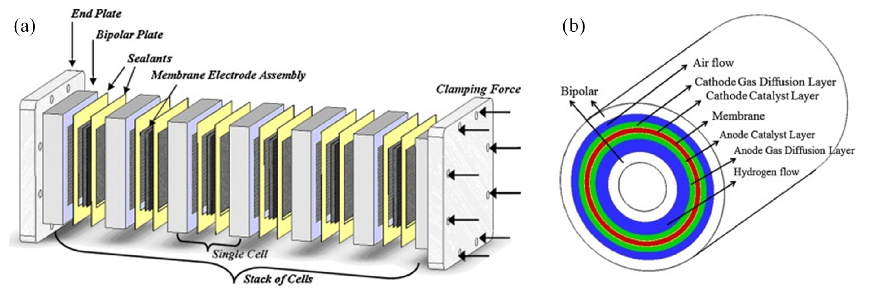
In this review, we focus on the tubular PEMFC (Fig. 1b) rather than the typical planar rectangular shape and summarize the structural advantages of this design and ongoing research. Afterwards, the development potential and improvement points of the tubular PEMFC as a lightweight energy source are discussed. It also covers lightweight, flexible PEMFCs, the materials used, and the manufacturing processes. Each of the improvements needed to make fuel cells competitive as portable energy sources is discussed.
2. Tubular shape PEMFC
The main form of the current PEMFC is a rectangular parallelepiped design, in which the MEA, bipolar plate, and end plate are vertically stacked. However, this planar-type PEMFC has limitations in terms of reducing the thickness and weight of the end plate to deliver a uniform contact pressure to the entire MEA area, and fastening parts are required. In addition, a gasket is required to prevent gas leakage, and a flow field is required for reactant supply and product removal. A new cylindrical PEMFC (Fig. 1b) design was proposed that can reduce the role of each part of the PEMFC. Cylindrical PEMFC has the following advantages over planar PEMFC. 1. Because the inside of the tubular tube act as a flow field, there is no need for a separate flow field and low pressure drop. 2. It delivers uniform contact pressure to the entire MEA area without end plates and increases the cathode surface area. 3. Active surface area increases, as the entire area of the flow channel becomes the active surface. 4. When sealed, a separate gasket is not required to prevent gas leakage. 5. Depending on the design, a separate clamp may not be required [21]. With the above advantages, research on the design, material, and manufacturing method of the tubular PEMFC can be a method for realizing a lightweight fuel cell.
2.1 Numerical modeling analysis of tubular PEMFC
Computational fluid dynamics (CFD) models are important tools in the modeling process. The CFD modeling approach helps to understand many design applications, and electrochemical reactions, which are difficult to realize experimentally. In particular, it helps to predict and understand mass transfer, fluid flow, and heat transfer phenomena and is used for design evaluation. It is a good research method that can control various variables and predict performance compared to manufacturing the cell.
Numerical studies were performed to predict the design effect and performance based on the shape of the tubular fuel cell, which is a new design [21–27]. Coursange et al. confirmed the advantages of tubular PEMFC design for material transport through CFD [21]. Through modeling, compared to the planar PEMFC, the tubular PEMFC showed better performance in the high current density region. It has been found that it is easier to maintain the humidification of the membrane as well as a more uniform mass transfer of the reactant gases. Al-Baghdadi et al. proposed a CFD model for the analysis of transport phenomena, such as convective and diffusive heat and mass transfer, electrode kinetics, transport and phase change mechanisms of water, and potential fields of tubular PEMFCs (Fig. 2) [22,23]. The model analysis helped to identify important parameters and provided insight into the physical mechanisms that lead to fuel cell performance and durability under various material conditions. Sierra et al. performed a 3D numerical study on a cylinder PEMFC model [24]. The Cylindrical PEMFC design with three other Geometries flow fields was compared with the Planar PEMFC. The pressure, flow concentration, and current density were uniformly distributed according to the cylindrical geometry compared to the rectangular design, confirming the development potential of the cylindrical PEMFC. Saghali et al. studied the superiority of conical pipe PEM fuel cells compared to cylindrical PEM fuel cells [25]. The authors confirmed that the performance of the conical PEMFC was better than the cylindrical PEMFC, and the fuel cell performance increased as the conical angle increased. Tubular PEMFCs with various MEA structures are also being studied. Mohammadi-Ahmar et al. modeled for a tubular PEMFC with a different MEA arrangement, not a cylindrical MEA [26]. A square tubular PEMFC has also been proposed [27]. It was shown that the difference in performance occurred due to the effect of the distance between the MEA and the core of flow.

Through CFD, the performance and potential of the tubular PEMFC in several controlled variables were confirmed, but the applied design was limited. As there are many design variables, optimization of design parameters through CFD modeling for various tubular designs will be very important for commercialization of tubular PEMFCs.
2.2 Fabrication of tubular PEMFC
It is also important to produce a numerically organized design as a real model. There have also been studies that analyzed the structural advantages of tubular PEMFCs as actual models. In addition, research on materials and manufacturing methods to implement the tubular PEMFC design is ongoing. Lee et al. developed a cylindrical air-breathing PEMFC to integrate a serpentine flow-channel structure into a cylindrical configuration (Fig. 3a) [28]. Aluminum was used as the current collector, as well as the support material of the anode, and a spiral channel for the hydrogen supply was located on the surface of the cylinder. The MEA was rolled into the middle of the anode cylinder as the current collector of the cathode, 0.5 mm gold-coated stainless steel was used, and there were slits and ribs; therefore, it was designed to supply air (oxygen) through the slits. The cathode current collector was wrapped around the anode current collector, where the MEA was wound, and the bolts and nuts were tightened to reduce the contact resistance between the cathode and anode. The volume of the manufactured cylinder PEMFC was 30 cc and the weight was 82 g. The difference in contact pressure between the planar PEMFC and the tubular PEMFC was compared through pressure-sensitive film as well as numerical analysis. Experimentally, it was proved that the elastic modulus of the current collector has a great effect on the contact pressure of the planar PEMFC, whereas the contact pressure of the tubular design is determined by the design characteristics and even pressure is transmitted to all surfaces. It was confirmed that the planar PEMFC had contact pressure concentrated at the edge, while the cylinder-shaped PEMFC delivered uniform contact pressure to the entire MEA area; thus, the performance of the cylinder PEMFC was better. Although it could not be made lighter with the support of the anode and the fixing parts such as bolts and nuts, it is meaningful in manufacturing the tubular PEMFC.

The manufacture of tubular PEMFC focused on lighter weight was attempted [29]. The MEA was wound on an anode support with holes without a flow field, and a copper mesh was used as a current collector instead of a bipolar plate. The MEA of PEMFC is fixed through a copper wire, so it has a lighter material and assembly method (Fig. 3b). The authors found that cylindrical PEMFC removed liquid water better than planar PEMFCs and had much higher volumetric and gravimetric power density. The electrochemical impedance spectroscopy (EIS) measurements confirmed that contact resistances have a significant influence on the performance of tubular PEMFCs and are important factors in tubular design. It was considered that fixation via copper mesh and wire did not deliver a sufficiently uniform contact pressure across the entire MEA. Suseendiran et al. proposed a cylindrical PEMFC design in which two semi-cylindrical cathode current collectors were used (Fig. 3c) [30]. A contact pressure was applied to the active area through a compression cable, and a lighter fuel cell was manufactured by applying a thinner current collector (0.355 mm). The ohmic resistance is further reduced by the electrodeposition of the gold layer. In addition, sealing without a gasket was possible using an acrylic-based adhesive. Through optimization of the slots and ribs, a current density of 400 mA cm−2 at 0.6 V was obtained, which is the best performance reported for air-breathing cylindrical PEMFCs to date.
After that, research for lighter PEMFC was also conducted, and the design was applied to remove more parts. Hwang et al. developed a novel design for lightweight tubular PEMFCs that are fabricated without fixtures (Fig. 3d) [31]. The conical design unit is assembled by accommodating the cell units like paper cups overlapping each other. Therefore, assembly parts such as clamps, bolts, and nuts for holding the parts are not needed. Moreover, the flow field is removed using the inside of the tube as a channel, and a compact bipolar plate can be applied using a 50-μm thin stainless-steel mesh as the current collector. By applying a conical design, an easy serial connection is possible using a bended-type connection without an external serial connection. The 2-cell PEMFC stack was very light at 0.22 g and had a specific weight power density of 897.7 W kg−1.
As mentioned above, studies on tubular PEMFC have been conducted in various ways. Various designs, manufacturing methods, and materials were applied. The cylindrical design of PEMFC has full potential as a lightweight PEMFC fabrication method. At the same time as design optimization of light weight, material transport, or electrochemical performance through numerical modeling, research on materials and manufacturing methods that can implement it is necessary. For performance improvement, material and design approaches to improve ohmic resistance and contact pressure are possible. It is also important to improve the sealing method that can be maintained during operation by improving the adhesive method such as Nafion thermal bonding, rubber/resin or acrylic based adhesives. In addition, it is necessary to consider how to maintain the driving temperature of the cell. In future research, it will be necessary to develop a cylindrical PEMFC stack that uses cheaper, stronger, and lighter materials to reduce the weight and volume of the fuel cell, and improve durability and performance.
3. Flexible PEMFC
3.1 Flexible end plates and bipolar plates
A flexible power supply is required, as the demand for devices with movement, such as wearable and roll-up devices, increases. There is a limit to realizing a flexible or stretchable PEMFC through the materials and designs of commonly used commercial PEMFC components. Hard metal materials are used for the end plate, and hard materials, such as metal and graphite composites, are used for the bipolar plate. The realization of a flexible PEMFC is possible only when the plate is replaced with another flexible material.
The fabrication of flexible fuel cells using flexible polymer substrates was first reported by Ito et al. [32]. Ten micro-direct methanol fuel cells can be fabricated on one substrate using a 0.3 mm thick polysulfide substrate with a diameter of 0.5 mm. The performance was maintained even during the bending tests. Tominaka et al. proposed a flexible on-chip fuel cell by fabricating inexpensive and flexible cycloolefin polymer films instead of brittle silicon films [33,34]. They allowed the current to flow through the circuit of the Au film on the substrate and applied a design that does not require a separate flow field using methanol without gas flow as fuel by making it micro-sized.
A study on a flexible PEMFC with a gas flow field and a slightly larger MEA active area is also being conducted. Chang et al. reported a bendable PEMFC fabricated on a polydimethylsiloxane (PDMS) substrate with a flow field through a stainless-steel mold [35]. A current collector was fabricated by sputtering Ni and Au directly onto PDMS with a flow field. A PEMFC fabricated with the flexible properties of PDMS is bendable. However, in the metal film produced through sputtering, the electrode was delaminated after the bending test and the ohmic resistance increased, resulting in a difference in performance before and after bending.
Polymer-based flexible PEMFCs are affected by the tensile and compressive stresses generated during bending. A film-type metal electrode produced through sputtering is vulnerable to mechanical movements such as bending, leading to an increase in ohmic loss. Therefore, electrodes such as metal meshes and nanowire (NW) networks have been studied as flexible electrodes that do not delaminate or break after bending. Park et al. developed a flexible, lightweight, and thin PEMFC using a PC plate and stainless metal mesh (Fig. 4) [36]. A flow field was formed on the PC film by pressing the flow-channel mold on the PC film, and a gold-coated metal mesh was used as the current collector. As a result, it was possible to fabricate a lightweight (2.23 g) and flexible PEMFC with a roll-up shape and an S-shape with an area of 9 cm2. The metal mesh electrode was confirmed to have good durability, maintaining its performance even after repeated bending tests over 200 times. Chang et al. reported a flexible PEMFC based on PDMS coated with a flexible current-collecting layer of an Ag NW infilrated network [37]. The synthesized Ag NW were placed on a stainless-steel mold and annealed to improve the connection between the Ag NWs. Subsequently, PDMS was spread on the mold to ensure good bonding between PDMS and the Ag NW network. Consequently, when bent, the performance increased further.

The process of creating a flow field on a polymer film through a stainless-steel mold is relatively complicated, thus 3D printing has been proposed as a simple method [38]. Manufacturing a flexible flow field plate through 3D printing not only simplifies the process but also saves time and cost.
3.2 Contact pressure of flexible fuel cells
In comparison to metal, the cells fabricated as described above use a relatively soft and thin polymer as a substrate. Therefore, a uniform high clamping force provided by the end plate cannot be expected in the existing PEMFC. The performance varies depending on the compression pressure and degree of bending. Chang et al. studied the change in performance, with respect to bending [39]. It was confirmed that performance increased as the bending radius decreased. Structural modeling results showed that the decrease in resistance and the resulting improvement in performance were due to an increase in the compressive force perpendicular to the membrane electrode assembly, which was investigated through finite element simulations of bendable fuel cell internal stress. Furthermore, it was demonstrated that by adjusting the stiffness of the PDMS plate, the pressure transmitted to the MEA could be controlled and the performance could be improved. Park et al. investigated the effect of the assembly pressure on the performance of a bendable PEMFC based on Ag NW current collectors [40]. As the applied pressure increased, the peak power density of the fuel cell increased, and the value converged when a certain amount of pressure was applied. In addition, the torsional performance of the bendable PEMFCs was studied [41]. It was confirmed that when bending was added to torsion, higher compressive stress was applied and a higher performance was observed, confirming that bending had a greater effect on fuel cell performance than torsion.
Through the above studies, it is confirmed that the contact pressure and performance change according to the movement is large. This deviation can be a problem for stable use of flexible PEMFC. Therefore, it is necessary to consider a structure that transmits a constant contact pressure. In addition, it is necessary to improve the sealing method to fix the components and prevent the outflow of gas, and the contact problem of the components according to the operating conditions such as temperature and humidity should be considered. Research into materials and technologies that can fabricate thinner plates for more flexible movement and smaller volumes is also needed.
3.3 Thin and flexible GDL
For flexible PEMFC, not only the bipolar plate and end plate, but also the flexibility of the GDL is required. Among the components of MEA, the membrane and catalyst layer are bendable materials, but in the case of the GDL, they can be damaged by repeated bending [42]. The Carbon Paper GDL, which is intertwined with the Carbon Fiber, has lowered performance due to damage to carbon fiber when applied to Flexible PEMFC. Carbon Cloth GDL is not damaged by bending, but has the disadvantage of low performance. Therefore, it is necessary to develop a thin, flexible, and capable GDL that can maintain high performance.
Ning et al. manufactured a new composite electrode with a porous CNT membrane and carbon paper, which had advantages such as excellent conductivity, flexibility, and high gas permeability [43]. By combining this with a flow field made of a PC plate, a specific volume power density of 5190 W L−1 and a specific mass power density of 2230 W kg−1 were obtained. In addition, this flexible PEMFC has good durability, maintaining 89.1% of its original performance even after 600 bending cycles and maintaining its original performance even after being dropped five times from a height of 30 m. Kang et al. fabricated the bendable MEA by simply coating conventional carbon papers with manually fabricated Ag NWs [44]. The coated Ag NW effectively connected the carbon fiber damaged by mechanical bending and maintained the electrical conductivity of the GDL. The performance was maintained even in more than 100 repetitive bending. Wei et al. further developed a flexible GDL by coating a CNT powder and PTFE mixture on a CNT membrane (Fig. 5) [45]. It has advantages such as a thickness of less than 40 μm, high flexibility, and mass productivity. The flexible fuel cell manufactured using the thin GDL was very thin (less than 90 μm) (Fig. 5c). Furthermore, when the new GDL is applied, a performance improvement of approximately 58% is observed. The air-breathing PEMFC fabricated from the new GDL significantly increased the power density by volume to 15,600 WL−1 and the power density by weight to 9,660 W kg−1. Both thin and good performances resulted in improved results.
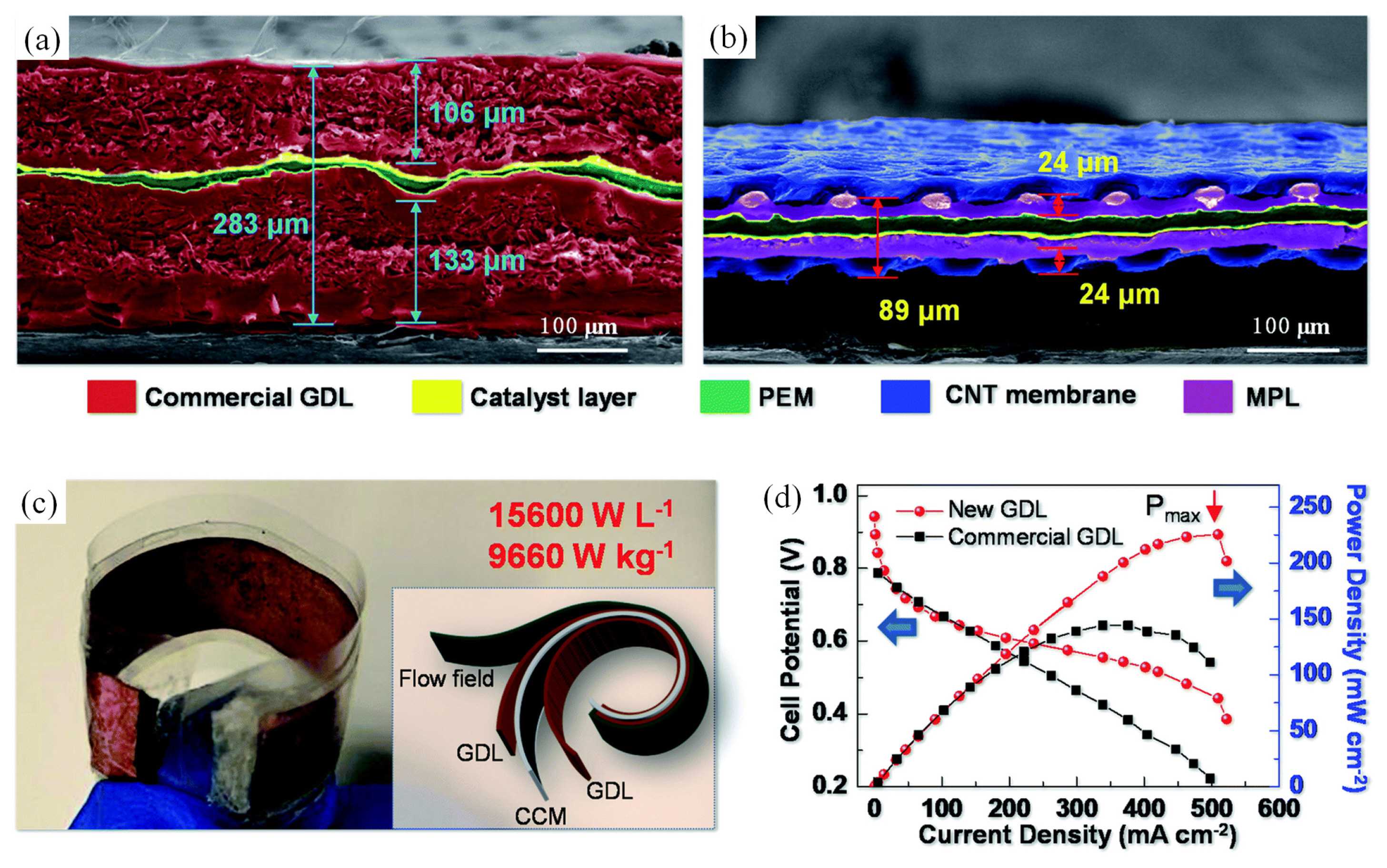
Application of the new GDL in flexible PEMFCs. (a) MEA made with a commercial GDL with carbon paper after hot-pressing. (b) MEA made with our new GDL. (c) Flexible PEMFC with a MEA made with the new GDL. The length and width are 5 cm and 1 cm, respectively, and the working area is 5 cm2. The inset shows the structure of the flexible air-breathing PEMFC made with the new GDL. (d) Polarization curves of PEMFCs made with the commercial GDL and the new GDL. Reproduced with permission from Ref. [45].
3.4 Flexibility of fuel supply
Even if the fuel cell becomes flexible, the method of supplying fuel is also a challenge that needs to be addressed. The hydrogen fuel for a PEMFC is supplied by a large, rigid, high-pressure cylinder or storage vessel for low-temperature liquid hydrogen. Therefore, there is a problem in applying the flexible PEMFC system to the device, and the flexibility of fuel storage and supply is also a consideration. Recently, a flexible fuel cell pack that combines a hydrogen supply to the anode has been developed. Wang et al. fabricated a flexible and adaptable hydrogen generator by storing liquid formic acid in the pores of a silica aerogel [46]. Even with flexible movement, hydrogen can be constantly generated at room temperature. However, the output power and power density need to be improved.
3.5 Flexibility through structural design
In general, the tubular shape is not easy to bend. Flexible movement requires a special structural approach, such as a bendable straw. Even with tubular PEMFC design, efforts are being made to realize flexible fuel cells. Hwang et al. applied a conical reverse-truss origami design to a tubular PEMFC, to enable flexible movement (Fig. 6) [31]. Origami is a representative method used to make 3D structures flexible, reducing volume and enabling 3D movement. The bending angle can be adjusted using the origami method, and the performance was maintained at over 90% at all angles from 0 to 90 degrees (Fig. 6e). Furthermore, the volume can be controlled by folding. However, the durability of stainless steel is insufficient and the application of other materials is required.

4. Conclusions and future outlook
Here, the design and materials of PEMFC for light weight and flexibility were reviewed. Design, materials, and assembly methods for lightweight and flexible PEMFCs that can replace rigid end plates and bipolar plates have been extensively investigated. First, we mentioned the tubular PEMFC design that can simplify the end plate and bipolar plate and eliminate the fixed parts. Tubular PEMFC has potential as a lightweight PEMFC design, but it is insufficient to have industrial competitiveness compared to other energy sources. Design optimization of weight reduction, mass transfer, and electrochemical performance is progressing through numerical modeling, and at the same time, it is necessary to explore materials and manufacturing technologies that can implement them. Second, the materials and designs applied for lightweight flexible PEMFC were described. It is judged that the biggest obstacle is the change in the contact pressure applied to the MEA according to the change in shape due to the application of a flexible polymer. Therefore, methods of transmitting contact pressure and materials that can be made thinner for more flexible movement and smaller volumes will need to be explored.
For competitive lightweight flexible PEMFC, additional research on lightweight and flexible materials and innovative design is needed. Efforts are required to develop the energy density per volume and energy density per weight of the fuel cell system, such that PEMFC can be applied to small and flexible devices. Furthermore, it will be useful not only for PEMFCs, but also for water electrolyzers, anion exchange membrane fuel cells, and CO2 conversion devices in the form of MEA, composed of polymer membrane electrolytes and catalysts with similar structures.
Acknowledgements
This work was supported by Project IBS-R006-A2 in Korea.