A Feasibility Study for a Stratospheric Long-endurance Hybrid Unmanned Aerial Vehicle using a Regenerative Fuel Cell System
Article information
Abstract
In the stratosphere, the air is stable and a photovoltaic (PV) system can produce more solar energy compared to in the atmosphere. If unmanned aerial vehicles (UAVs) fly in the stratosphere, the flight stability and efficiency of the mission are improved. On the other hand, the weakened lift force of the UAV due to the rarefied atmosphere can require more power for lift according to the weight and/or wing area of the UAV. To solve this problem, it is necessary to minimize the weight of the aircraft and improve the performance of the power system. A regenerative fuel cell (RFC) consisting of a fuel cell (FC) and water electrolysis (WE) combined PV power system has been investigated as a good alterative because of its higher specific energy. The WE system produces hydrogen and oxygen, providing extra energy beyond the energy generated by the PV system in the daytime, and then saves the gases in tanks. The FC system supplies the required power to the UAV at night, so the additional fuel supply to the UAV is not needed anymore. The specific energy of RFC systems is higher than that of Li-ion battery systems, so they have less weight than batteries that supply the same energy to the UAV. In this paper, for a stratospheric long-endurance hybrid UAV based on an RFC system, three major design factors (UAV weight, wing area and performance of WE) affecting the ability of long-term flight were determined and a simulation-based feasibility study was performed. The effects of the three design factors were analyzed as the flight time increased, and acceptable values of the factors for long endurance were found. As a result, the long-endurance of the target UAV was possible when the values were under 350 kg, above 150 m2 and under 80 kWh/kg H2.
1. Introduction
Stratospheric long-endurance hybrid UAVs have been developed to perform not only military missions, such as surveillance and reconnaissance of a very wide range, but also commercial missions, such as meteorological observation, aerial photography, communication relaying, internet network construction and disaster observation, at higher altitudes than normal atmospheric airplanes. Because the UAV flies in the stratosphere, where the weather barely changes, it is possible to ensure stability, which is one of the most important factors when the UAV is operated. Additionally, PV systems can generate more power there because they are exposed to a greater quantity of solar radiation than in the atmosphere. Because the UAV is operated at a lower altitude than satellites, it is easy to maintain and can minimize data loss and delay. Therefore, it is possible to improve the results of the mission and provide continuous services by operating the UAV in the stratosphere [1].
Many research teams have developed high-altitude long-endurance (HALE) hybrid UAVs. NASA developed the Pathfinder series and Helios until 2003 under the Environmental Research Aircraft and Sensor Technology (ERAST) project [2-4]. These UAVs apply hybrid systems that consist of PVs, batteries, and FC systems. The total weight of the Pathfinder-plus is 317 kg, its wing area is 87.12 m2 and its maximum altitude is approximately 24 km. Helios is 907 kg, with a wing area of 183.58 m2, and can fly at 29.5 km [3]. Thales Alenia Space developed StratoBus, an airship driven by hybrid systems that consist of solar cells, batteries, polymer electrolyte membrane fuel cells (PEMFCs) and polymer electrolyte membrane water electrolysis (PEL) systems. The target altitude is 20 km, and its endurance is 5 years [1]. Boeing developed the Solar Eagle, which applies hybrid systems that consist of solar cells, solid oxide fuel cells (SOFCs), and PEL systems. Solar Eagle has a target 20-km altitude and 5-year endurance [1,4]. QinetiQ developed Zephyr, which uses solar cells and Li-S batteries. Zephyr achieved an approximately 21.5 km altitude and 336 h, 21 min endurance in 2010 [3-6]. Despite these developments of stratospheric long-endurance UAVs, there are still issues that should be solved to maintain stratospheric long-endurance flight. Providing an additional supply of fuel is impossible in the stratosphere, and PV systems cannot generate power at night. Thus, a secondary power system is necessary. Furthermore, stratospheric long-endurance UAVs should endure extreme conditions, such as a very low temperature of -56.5 ℃, high ultraviolet index, and low air density [1]. Additionally, because the lift force of the UAV in the stratosphere is less than in the atmosphere, it is necessary to make the weight of the UAV light and the wing area large.
RFC systems can continuously produce hydrogen and oxygen using the extra PV energy after the PV systems, which supply the power required for the UAV in the daytime, and hydrogen and oxygen, which are used to generate power through the FC systems at night. Water is generated by an electrochemical reaction in the FC stack and is used to generate hydrogen and oxygen by electrolysis in the PEL stack. Hence, additional fuel is not necessary. RFC systems can be a great solution to the need for an additional fuel supply and power generation at night.
In this paper, we studied the feasibility of a stratospheric long-endurance hybrid UAV based on an RFC system. The specific energy of RFC systems is 400~1000Wh/kg, higher than the 240 Wh/kg of Li-ion battery systems [4,7], making them lighter than batteries to supply a given energy to the UAV. The use of RFC systems would therefore make the UAV lighter. However, because the present technical level of the RFC systems and the generation efficiency of hydrogen-oxygen is low, achieving a long-endurance mission is hard. Therefore, 3 design factors (weight of the UAV, wing area and performance of WE) that affect the performance of the UAV were set to find objective values to enable meeting the long-endurance objective. Through simulation, the effects of the factors on flight time were analyzed, and objective values of these factors were found to enable the operation of the UAV for long-endurance tasks. Then, the feasibility of the long-endurance hybrid UAV based on the RFC system was evaluated at a target altitude of 18 km.
2. Modeling
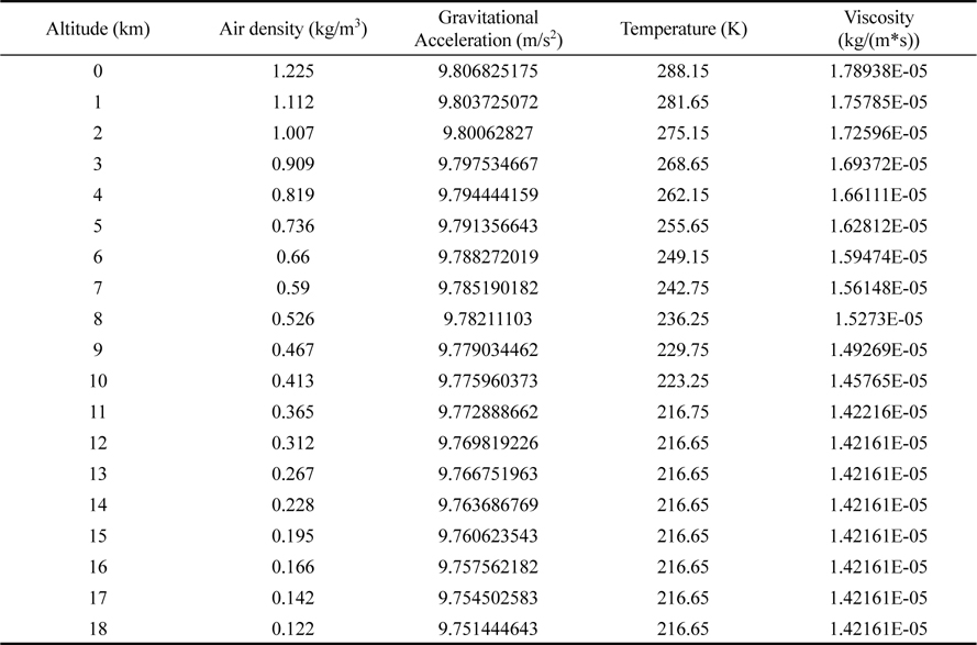
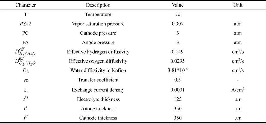
Conditions that vary with altitude, such as density, gravity, temperature and viscosity, are shown in Table 1 [8], and the parameters needed to calculate the modeling equations are shown in Table 2.

Parameters for modeling
2.1 Unmanned aerial vehicle
Aerodynamic equations are used to calculate the required power of a UAV, and the values of Table 1 and Table 2 are used to solve the equations. Fig. 1 shows the power applied to a UAV.

Forces applied to a UAV.
The weight (W) of a UAV is calculated by Eq. 1.

The lift (L) force is related to the weight and can be calculated by Eq. 2 [9].

The minimum velocity (v) of a UAV is calculated by Eq. 3 [9].

The drag (D) force is calculated by Eq. 4 [9]

The thrust (Tth) force is related to the drag and is calculated by Eq. 5 [9].

Using Eq. 1-5, the output power of a UAV considering efficiencies(PUAV) is calculated by Eq. 6 [9].

The output energy of a UAV(EUAV) is calculated by Eq. 7 [6,9].

2.2 Photovoltaic cell
The installation area of the PV cells is assumed to be 75 % of the total wing area. Fig. 2 shows the power generated by PV cells per unit area over time (PPVA). The total power generated considering the area of the PV cells and their efficiency (PPV) can be calculated by Eq. 8.

Power per unit area generated by the photovoltaic system as a function of time.

The total energy generated by the PV cells (EPV) is calculated by Eq. 9.

2.3 Regenerative fuel cell
2.3.1 Fuel cell
The FC system is a 2.5 kW PEMFC. The activation area of the cells is 60 cm2. The FC stack is a dead-end type and consists of 40 cells. Fig. 3 shows the performance curve of the FC stack. The FC stack obtains a maximum power of approximately 2.5 kW at a current density of 2.05 A/cm2. Table 3 shows the driving conditions of the stacks.

I-V curve of a fuel cell and power of a fuel cell stack.
The cell voltage of a fuel cell can be calculated by subtracting the activation loss, ohmic loss and concentration loss from the thermodynamic equivalent potential. The activation loss of the anode can be neglected because it is much smaller than that of the cathode. The cell voltage of a fuel cell is calculated by Eq. 10-13 [10,11].


The power of the FC systems supplied to the UAV is calculated by Eq. 14.

The power generated by the FC systems is calculated by Eq. 15.

The energy generated from the FC stacks is calculated by Eq. 16.

The amounts of hydrogen and oxygen consumed are calculated by Eq. 17-18 [10, 11].


The amount of water generated is calculated by Eq. 19.

2.3.2 Water electrolysis
Using the extra energy generated by the PV system in the daytime, the WE systems electrolyze water. When the PV power is greater than the power required to run the UAV, the power required by the WE systems to generate the hydrogen and oxygen is calculated by Eq. 20.

The energy required by the WE systems to generate the hydrogen and oxygen (EPEL) is calculated by Eq. 21.

The masses of hydrogen and oxygen generated by the WE systems are calculated as the ratio between the energy supplied to the PEL stack and the energy required to generate 1 kg of hydrogen or oxygen, per Eq. 22-23.


The amount of water consumed is calculated by Eq. 24.

3. Simulation
3.1 Assumptions
1) The intermediate values of each design factor are set as the reference points.
2) The climbing angle of a UAV is fixed at 10 degrees. (If the UAV arrive at the target altitude (18 km), then the angle is fixed at 0 degrees.)
3) Angle of attack is the same as the angle of climb in this simulation.
4) The aspect ratio of UAV wings is set to 20~22.
5) The installation area of PV cells is assumed to be 75% of the total wing area.
6) The WE systems make pure hydrogen and oxygen. Pure water is made by hydrogen and oxygen in the FC systems.
7) Before a UAV takes off, the water tanks contain the water required to generate the hydrogen and oxygen used during a level flight for one day.
8) One cycle is set as one day (24 hours). If the flight time is over 2 cycles (50 hours), a UAV is considered to be long-endurance.
3.2 Description of the design parameters
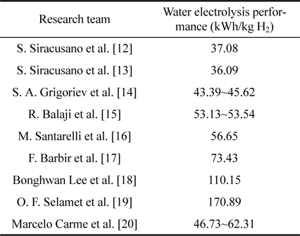
In this simulation, the design factors affecting the flight time of a UAV are the weight of the UAV, the wing area and the performance of the WE. The ranges of the design factors shown in Table 4 refer to the values confirmed by existing research results, although they are considered to be improvable. The range of performance values of the RFC within the design factors refers to the performance of the WE. Tables 5~7 show existing research results of the weight of a UAV, the wing area and the performance of the WE. In Table 5, the range of weights covers 150, 250, 350, 450, and 550 kg and the reference value is 350 kg. In Table 6, the range of wing areas covers 50, 100, 150, 200, and 250 m2 and the reference value is 150 m2. In Table 7 [12-20], the range of performances of the WE is 30, 55, 80, 105, and 130 kWh/kg H2 and the reference value is 80 kWh/kg H2. In the simulation, one of the three design factors is changed, and the others are fixed.
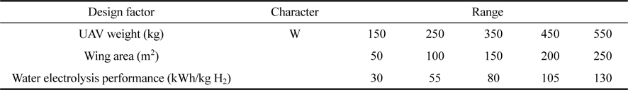
Design factors of UAV based on RFC and the ranges of values considered
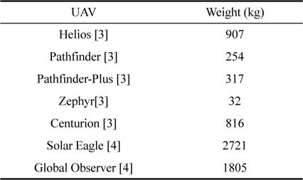
Conventional UAV weight values
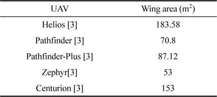
Conventional wing area values
4. Results and discussion
4.1 Correlation of design factors
The selected design factors have a strong correlation among them. The weight of a UAV affects its required power and the amount of hydrogen and oxygen consumed. The wing area affects the lift force and PV cell area. The lift force affects the required power of the UAV, the PV cell area affects the energy supplied to the UAV, and the energy supplied to the WE affects the amount of hydrogen and oxygen generated. In the WE system case, because the energy supplied to the WE systems in one day is limited, the performance of the WE systems (required energy per unit hydrogen/oxygen weight) affects the total amounts of hydrogen and oxygen generated.
4.2. Flight path
Fig. 4 shows the basic flight path at specific values of the weight of a UAV (350 kg), wing area (150 m2) and performance of the WE systems (80 kWh/kg H2). In the various simulation cases, because the power of the UAV varies according to its weight and wing area, the time needed to reach 18 km altitude can be slightly different in each case.

Flight path over time with a UAV weight of 350 kg, a wing area of 150 m2, and a water electrolysis performance of 80 kWh/kg H2.
4.3 Analysis of UAV weight
Figs. 5-6 show the amount of hydrogen and the power as functions of the flight time when the weight of a UAV is changed but its wing area and the performance of its WE systems are fixed. In Fig. 5, long-endurance operation is possible up to a weight 350 kg at the fixed reference wing area and performance of the WE systems. As the weight of a UAV increases, the power needed by it also increases. If the weight is 450 kg or more, long-endurance operation is impossible because the hydrogen is used up before the sun rises the next day, so the FC systems cannot supply the required power to the UAV based on the reference conditions, as shown in Fig. 6. On the other hand, if the weight is 350 kg or less, the UAV is capable of long-endurance operation because the amount of hydrogen is sufficient and the UAV continuously is provided the required power.

Flight time according to the weight of the UAV.

Amount of hydrogen and power generated with time when the weight of the UAV is changed and the wing area and performance of the WE systems are fixed.
4.4 Analysis of wing area
Figs. 7-8 show the amount of hydrogen and power as a function of the flight time when the wing area is changed and the weight of the UAV and performance of the WE systems are fixed. Fig. 7 shows that long-endurance operation is possible when the wing area is 150 m2 or more at the fixed reference weight of a UAV and performance of the WE systems. However, when the wing area is 50 m2, there is not sufficient power to take off, as the wing area and PV cell area are too small relative to the weight. When the wing area is 100 m2, the UAV can take off, but the power required is greater than that generated by the PV cells and FC systems, so it is incapable of long-endurance operation. In Fig. 8, the case of a wing area of 150 m2, which is capable of long-endurance operation, and the case of a wing area of 100 m2, which is incapable of long-endurance operation, are compared. When the wing area is 150 m2 or more, the amount of hydrogen produced is sufficient, so the UAV continuously receives the required power, but when the wing area is 100 m2 or less, the UAV is incapable of long-endurance operation because the power required is greater than that generated by the PV cells and FC systems.

Comparison of flight time according to the wing area.

Amount of hydrogen and power generated according to time when the wing area is changed and the weight of the UAV and performance of the WE systems are fixed.
4.5 Analysis of performance of water electrolysis
Figs. 9-10 show the amount of hydrogen and power according to the flight time when the performance of the WE systems is changed and the weight and wing area are fixed. Fig. 9 shows that long-endurance operation is possible when the performance of the WE systems is no more than 80 kWh/kg H2 at the fixed reference weight and wing area. However, when the performance of the WE systems is 105 kWh/kg or 130 kWh/kg H2, the UAV is incapable of long-endurance operation because the amount of energy needed to generate the required daily hydrogen and oxygen is too high. In Fig. 10, the cases where the performance of the WE systems is 80 kWh/kg H2, which is capable of long-endurance operation, and the case where the performance is 105 kWh/kg H2, which is incapable, are compared. When the performance is 80 kWh/kg H2, the UAV is capable of long-endurance operation because there is sufficient hydrogen, so the UAV continuously receives the required power. However, when the performance is 105 kWh/kg H2, the WE system cannot make enough hydrogen, so the UAV is incapable of long-endurance operation.

Comparison of flight time according to the performance of the water electrolysis.

Amount of hydrogen and power generated according to time when the performance of the WE systems is changed and the weight of the UAV and wing area are fixed.
4. Conclusions
For the feasibility study regarding reaching the goal of a stratospheric long-endurance hybrid UAV based on an RFC system, 3 design factors (UAV weight, wing area and performance of WE) affecting the capability of long-endurance operation were determined, and then, simulations were performed. The developed simulation consists of the fundamental equations for the UAV, photovoltaic cell, and RFC, including the fuel cell and water electrolysis. Each design factor has a reference value based on existing research works. If a UAV satisfying all 3 design factors is developed, the UAV is capable of long-endurance operation. However, if even one of the design factors does not satisfy the reference value, the UAV is incapable of long-endurance operation. If one factor, such as the weight of a UAV, is significantly improved, the UAV may be capable of long-endurance operation, even though the technical level of the other factors may be slightly weak.
To develop a good stratospheric long-endurance hybrid UAV based on RFC systems, many technologies, such as the aviation, fuel cells, water electrolysis, and PV cells, must be improved. Therefore, it is expected that this simulation-based feasibility study can provide guidance for the technical goal of each element technology and effective directions of research and development for the total system.
Nomenclature
AR
aspect ratio
ASRohmic
area-specific resistance, Ωcm2
Awing
area, m2
CD
drag coefficient
CL
lift coefficient
D
drag force, N

effective hydrogen diffusivity, cm2/s

effective oxygen diffusivity, cm2/s
Dλ
water diffusivity in Nafion, cm2/s
Eact
activation loss, V
Econc
concentration loss, V
EPEL
energy required by the WE system to generate gases, Wh
EFC, stack
energy generated from fuel cell stack, Wh
Eohmic
ohmic loss, V
EPEL, 1kg H2
water electrolysis performance, kWh/kg H2
EPEL, 1kg O2
water electrolysis performance, kWh/kg O2
EPV
total generated energy from PV cells, Wh
Ethermo
thermodynamic equivalent potential, V
EUAV
output energy of a UAV, Wh
F
Faraday constant, C/mol
g
gravitational acceleration, m/s2
i
current density, A/cm2
iL
limiting current density, A/cm2
io
exchange current density, A/cm2
L
lift force, N
LC
chord, m
m
mass, kg
mH2, con
amount of hydrogen consumption, kg/h
mH2, gen
amount of hydrogen generation, kg/h
mH2O, con
amount of water consumption, kg/h
mH2O, gen
amount of water generation, kg/h
mO2, con
amount of oxygen consumption, kg/h
mO2, gen
amount of oxygen generation, kg/h
n
number of electrons
PA
anode pressure, atm
PC
cathode pressure, atm
PPEL
power required by the WE system to generate gases, W
PFC, BOP
power of BOP of fuel cell, W
PFC, stack
power generated from fuel cell system, W
PFC, sys
power generated from fuel cell system, W
PPV
power considering the area of the PV cells and their efficiency, W
PPVA
generated power by PV cells per unit area according to time, W
PSAT
vapor saturation pressure, atm
PUAV
output power of a UAV considering efficiencies, W
R
gas constant, J/(mol*K)
SH2
stoichiometry of hydrogen
SO2
stoichiometry of oxygen
T
temperature, , K
tA
anode thickness, μm
tC
cathode thickness, μm
tM
electrolyte thickness, μm
Tth
thrust force, N
v
minimum velocity, m/s
Vcell
cell voltage, V
W
weight, N
xO2
mole fraction of oxygen
α
transfer coefficient
ηEF
efficiency according to environmental factors
ηinverter
efficiency of inverter
ηmotor
motor efficiency
ηprop
propeller efficiency
ηPV
photovoltaic cell efficiency
θ
climbing angle, degree
μ
viscosity, kg/(m*s)
ρ
air density, kg/m3
Acknowledgements
This work was supported by the Civil Military Cooperation Program (13-DU-SP-01-MKE) of the Civil Military Technology Cooperation Center and granted financial resources from the Ministry of Trade, Industry & Energy of the Republic of Korea.
References
S. H. Cho, M. J. Kim, Y. J. Sohn, and T. H. Yang, Trans. of the Korean Hydrogen and New Energy Soc., 25, 393 (2014).
Cho S. H, Kim M. J, Sohn Y. J, Yang T. H.C. L. Nickol, M. D. Guynn, L. L. Kohout and T. A. Ozoroski, AIAA Paper, 1050 (2007).
Nickol C. L, Guynn M. D, Kohout L. L, Ozoroski T. A.Y. Najafi, Diss. Master Thesis, Washington San Jose State University, (2011).
Najafi Y.K. B. Kim, I. Y. Yang, N. Y. Kim and B. H. Jang, Current Industrial and Technological Trends in Aerospace, 9, 39 (2011).
Kim K. B, Yang I. Y, Kim N. Y, Jang B. H.A. Rapiett, Diss. Master Thesis, University of Surrey, (2009).
Rapiett A.X.-Z. Gao, Z.-X. Hou, Z. Guo, J.-X. Liu and X.-Q. Chen, Energy Convers. Manag., 70, 20 (2013).
Gao X.-Z, Hou Z.-X, Guo Z, Liu J.-X, Chen X.-Q.T. H. Bradley, Modeling, Design and Energy Management of Fuel Cell Systems for Aircraft, Georgia Institute of Technology press, (2008).
Bradley T. H.N. Sissenwine, H. Wexler, S. Teweles and M. Dubin, The United States Committee on Extension to the Standard Atmosphere (COESA), (1976).
Sissenwine N, Wexler H, Teweles S, Dubin M.D. G. Hull, Fundamentals of Airplane Flight Mechanics, first ed., Springer, New York, (2007).
Hull D. G.F. Barbir, PEM Fuel Cells: Theory and Practice, second ed., ELSEVIER Academic press, Massachusetts, (2012).
Barbir F.R. P. O’hayre, S. W. Cha, W. Colella and F. B. Prinz, Fuel Cell Fundamentals, second ed., John Wiley & sons, New York, (2009).
O’hayre R. P, Cha S. W, Colella W, Prinz F. B.S. Siracusano, A. D. Blasi, V. Baglio, G. Brunaccini, N. Briguglio, A. Stassi, R. Ornelas, E. Trifoni, V. Antonucci and A.S. Arico, Int. J. Hydrogen Energy, 36, 3333 (2011).
Siracusano S, Blasi A. D, Baglio V, Brunaccini G, Briguglio N, Stassi A, Ornelas R, Trifoni E, Antonucci V, Arico A.S.S. Siracusano , V. Baglio, N. Briguglio, G. Brunaccini, A. D. Blasi, A. Stassi, R. Ornelas, E. Trifoni, V. Antonucci and A.S. Arico, Int. J. Hydrogen Energy, 37, 1939 (2012).
Siracusano S, Baglio V, Briguglio N, Brunaccini G, Blasi A.D, Stassi A, Ornelas R, Trifoni E, Antonucci V, Arico A.S.S. A. Grigoriev, V. I. Porembsky and V. N. Fateev, Int. J. Hydrogen Energy, 31, 171 (2006).
Grigoriev S. A, Porembsky V. I, Fateev V. N.R. Balaji, N. Senthil, S. Vasudevan, S. Ravichandran, S. Mohan, G. Sozhan, S. Madhu, J. Kennedy, S. Pushpavanam and M. Pushpavanam, Int. J. Hydrogen Energy, 36, 1399 (2011).
Balaji R, Senthil N, Vasudevan S, Ravichandran S, Mohan S, Sozhan G, Madhu S, Kennedy J, Pushpavanam S, Pushpavanam M.M. Santarelli, P. Medina and M. Cali, Int. J. Hydrogen Energy, 34, 2519 (2009).
Santarelli M, Medina P, Cali M.F. Barbir, Sol. Energy, 78, 661 (2005).
Barbir F.B. H. Lee, K. W. Park and H.-M. Kim, Int. J. Electrochem. Sci., 8, 235 (2013).
Lee B. H, Park K. W, Kim H.-M.O. F. Selamet, F. Becerikli, M. D. Mat and Y. Kaplan, Int. J. Hydrogen Energy, 36, 11480 (2011).
Selamet O. F, Becerikli F, Mat M. D, Kaplan Y.M. Carmo, D. L. Fritz, J. Mergel and D. Stolten, Int. J. Hydrogen Energy, 38, 4901 (2013).
Carmo M, Fritz D. L, Mergel J, Stolten D.