Triallyl Borate as an Effective Separator/Cathode Interphase Modifier for Lithium-ion Batteries
Article information
Abstract
Ni-rich layered oxides cathode has recently gained attention as an advanced cathode material due to their applicable energy density. However, as the Ni component in the layered site is increased, the high reactivity of Ni4+ results in parasitic reaction associated with decomposing electrolyte, which leads to a rapid decreasing the lifespan of the cell. The electrolyte additive triallyl borate (TAB) improves interfacial stability, leading to a stable cathode–electrolyte interphase (CEI) layer on the LNCM83 cathode. A multi-functionalized TAB additive can produce a uniformly distributed CEI layer via electrochemical oxidation, which implies an increase in long-term cycling performance. After 100 cycles at elevated temperature, the cell tested by 0.75 TAB retained 88.3% of its retention ratio, whereas the cell performed by TAB-free electrolyte retained 64.1% of its retention. Once the TAB additive formed CEI layers on the LNCM83 cathode, it inhibited the decomposition of carbonate-based solvents species in addition to the dissolution of transition metal components from the cathode. The addition of TAB to LNCM83 cathode material is believed to be a promising way to increase the electrochemical performance.
1. Introduction
Numerous energy conversion/storage systems have been investigated in response to the growing demand for environmentally friendly energy devices. Since their commercialization, lithium-ion batteries (LIBs) have attracted considerable attention among these candidates [1–5]. They have been pioneered in small-scale devices and are now regarded as an attractive energy source for electric vehicles. Due to the diversity of their application areas, the requirements for advanced LIBs vary accordingly. The most critical technical question referring to large-scale devices is how to increase the energy density of LIBs. This feature greatly influences specification of the cell, such as in terms of how far it can power an electric vehicle. As a result, numerous approaches for improving the energy density of LIBs are currently being developed.
One efficient way to increase the energy density is by replacing conventional electrode materials with advanced ones which have a large specific capacity with high working potential [6–10]. In this respect, Ni-rich layered oxides (LiNixCoyMnzO2) have received considerable notice owing to their relatively huge specific capacity comparing with conventional cathode material, namely lithium cobalt oxide [11–15]. As a result, many cell manufacturers have attempted to incorporate Ni-rich layered oxides in order to elevate the energy density of LIBs. Nonetheless, there is a restriction on using these materials in LIBs due to their unstable surface properties during electrochemical cycling. After charging Ni-rich layered oxides, an electrochemical reaction provides mainly Ni4+ species in the cathode. Because these species are quite electrochemically unstable, means of reducing them are being sought via an additional chemical reaction with electrolyte components in the cell [16–22]. Notably, Ni-rich layered oxides cathode materials have high Ni content, which significantly accelerates electrolyte decomposition due to increased Ni amount in the layered structure. As a result, a substantial amount of electrolyte decomposition occurs in cells composed of Ni-rich layered oxides cathode materials, resulting in rapid degradation of cycle performance [23,24]. At room temperature, such parasitic reactions can be well controlled by surface modification of inorganic materials such as Al2O3 [25–27], ZrO2 [28–30], TiO2 [31–33], and Li3PO4 [34–36]. However, suppressing electrolyte decomposition at high temperatures is challenging, implying that stable high temperature cycling should be improved to increase the practical energy density of the cell.
This work aims to demonstrate the effectiveness of triallyl borate (TAB) as an electrolyte additive for improving the interfacial stability of LNCM83 cathode materials (Fig. 1). The TAB additive contains two distinct functional groups: allyl and borate. It is anticipated that the allyl functional group will be effective at attempting to form cathode–electrolyte interphase (CEI) layers on the LNCM83 cathode via electrochemical reaction because C=C double bond can be easily decomposed under high potential, which leads to unstable cationic radical intermediate that can promote the formation of CEI layers on the electrode by additional electrochemical/chemical reactions in the cell. The borate functional group will be efficient in decreasing fluoride (F−) species remaining in the LIBs through chemical scavenging reaction [37,38]. In other words, electrochemical oxidation of the TAB additive easily forms CEI layers on the LNCM83 cathode, thereby preventing electrolyte decomposition. Its main functional group (borate) contributes to interfacial stability by preferentially scavenging for F− species, which are always associated with irreversible transition metal dissolution from the LNCM83 cathode. These strategies are used to deduce the electrochemical performance of the TAB additive and to verify its molecular mechanism in the cell via systematic analyses of cycled LNCM83 cathodes.

Schematic of the role of TAB in the LNCM83/graphite full-cell.
2. Experimental
To prepare the electrolyte, TAB (Aldrich) was added to the TAB-free electrolyte (EC:EMC = 1:2 + 1.0 M LiPF6, Donghwa Electrolyte) with 0.25 wt% (0.25 TAB), 0.75 wt% (0.75 TAB), and 1.25 wt% (1.25 TAB). The ionic conductivity of electrolytes was determined using an ion conductivity meter (CM-41X, TOA DKK) at room temperature.
A potentiostat was used to measure the linear sweep voltammetry (LSV) of each electrolyte. The cells comprised a carbon-coated Al current collector with Li metals and scanned from 3.0 to 5.0 V (vs. Li/Li+) with 1.0 mV s−1 of scan rate. For electrochemical voltage spectroscopy (EVS), the LNCM83 cathode was prepared as follows. A total of 1.6 mL N-methyl-2-pyrrolidone (Aldrich), 1.8 g LNCM83 cathode materials (L&F), 0.1 g polyvinylidene fluoride, and 0.1 g carbon were agitated for 1 h and slurries were cast on the Al substrates. This was then dried for 3 h at 120°C and then 12 h at 120°C in a vacuum oven. Thereafter, the cells were assembled with LNCM83 cathode and Li metals in addition to each electrolyte. The cells were charged by 5.0 mV for 20 min, and given a resting step for 20 min. Each step was repeated until the potential of the cell reached 4.3 V (vs. Li/Li+), and oxidative currents of the cells were recorded at each step, which can be regarded as the decomposition of electrolyte additive and de-lithiation of Li+ from LNCM83 cathode. The cyclic voltammetry (CV) was also measured using the cells above from 3.0 to 4.5 V (vs. Li/Li+) at a scan rate of 0.1–0.4 mV s−1. The diffusion coefficient of Li+ (DLi+) was calculated by using the Randles-Sevcik equation (Ip = 2.69 × 10⁵ n3/2 A DLi1/2 ν1/2 C).
For cycling performance, half-cells were fabricated by the LNCM83 cathode, Li metal anode, separator, and electrolytes. The cells were charged/discharged with 0.1 C (1.0 C = 180 mA g−1) for two cycles, and the current was then changed to 0.5 C in the ranges between 3.0 to 4.3 V (vs. Li/Li+). To determine rate capability, 2032-coin cells with identical potential ranges were tested by changing charging currents from 0.1 to 1.0 C. The galvanostatic intermittent titration technique (GITT) was used to take measurements as follows. After charging the cells with 0.1 C for 10 min, they were rested for another 10 min. Each step was repeated until the potential of the cell reached between 3.5 and 4.3 V (vs. Li/Li+). After cycling, the cells were disassembled the LNCM83 cathodes were recovered. They were rinsed with dimethyl carbonate and dried in a glovebox. Scanning electron microscopy (SEM; SEM-7800F, JEOL) was employed to characterize the surface morphology of the recovered LNCM83 cathode. The chemical composition of the recovered LNCM83 cathode was characterized by X-ray photoelectron spectroscopy (XPS, PHI 5000 Versa Probe II, ULVAC-PHI).
The chemical reactivity of the TAB additive with F− species was elucidated as follows. The 1.0 mol of TAB was mixed with 3.0 mol of tetrabutylammonium fluoride (TBAF; Aldrich) and stirred for 24 h. The solution was then analyzed by nuclear magnetic resonance (NMR; Agilent). Transition metals were quantified by inductively coupled plasma-mass spectroscopy for cycled anodes (ICP-MS; Fluo Time300/MicroTime 100, Thermo).
A graphite anode was prepared for full-cell evaluation. A total of 3.0 mL deionized water, 1.95 g graphite anode materials (BTR), 0.04 g styrene butadiene rubber (ZEON), 0.02 g carboxymethyl cellulose (Daicel Fine Chem Ltd.) were agitated for 30 min and slurries were cast on the Cu substrates. This was then dried for 30 min at 120°C and then 11 h at 110°C in a vacuum oven. The LNCM83/graphite full-cells were assembled using the LNCM83 cathode, the graphite anode, the separator, and each electrolyte. The cells were cycled between 3.0 to 4.2 V. After cycling was completed, the surface of LNCM83 cathodes and separators was analyzed by SEM.
3. Results and Discussion
The ionic conductivity of the TAB was measured as the amount of TAB additive increased in the TAB-free electrolyte (Fig. 2a). The TAB-free electrolyte revealed an ionic conductivity of 7.89 mS cm−1, while the TAB additive had a slightly lower ionic conductivity as its amount increased (0.25 TAB: 7.80 mS cm−1, 0.75 TAB: 7.60 mS cm−1). However, the ionic conductivity of the TAB additive was not significantly decreased for the use of LIBs [39,40]. LSV was used to determine the electrochemical oxidation behavior shown in Fig. 2b. There was no noticeable oxidative current in the TAB-free electrolyte between 3.0 and 5.0 V (vs. Li/Li+). When the potential exceeded 5.0 V (vs. Li/Li+), the oxidative currents continuously increased, suggesting electrolyte decomposition had been triggered [41,42]. On the other hand, in 0.75 TAB, a distinct electrochemical behavior was observed. The initial oxidative current was approximately 3.7 V (vs. Li/Li+), which would be interpreted as oxidative decomposition of the TAB additive. Interestingly, when the potential of the cell was over 5.0 V (vs. Li/Li+), the oxidation current decreased. This can be explained by the fact that when the TAB additive is decomposed electrochemically at 3.7 V (vs. Li/Li+), it forms an artificial CEI layer, thereby suppressing the main electrolyte decomposition at high potentials (>5.0 V, vs. Li/Li+). To determine whether the TAB additive could form CEI layers on the LNCM83 cathode, the TAB additive was further analyzed by EVS using LNCM83 cathode (Fig. 2c). To investigate the electrochemical reactivity of the TAB additive in the cell, the LNCM83 cathode was used as the working electrolyte and occurred oxidative currents at each potential were recorded in the EVS protocol. Although most of the oxidative currents came from de-lithiation of the LNCM83 cathode, there was a difference in electrochemical behavior around 3.7 V (vs. Li/Li+): the cell tested by the TAB additive had significantly higher oxidative currents than the TAB-free electrolyte. This indicates that the TAB increased the observed oxidation current to around 3.7 V (vs. Li/Li+), which is consistent with the LSV results. Thus, the TAB additive formed borate-functionalized artificial CEI layers on the LNCM83 cathode at around 3.7 V (vs. Li/Li+), which inhibited the decomposition of the electrolyte components.
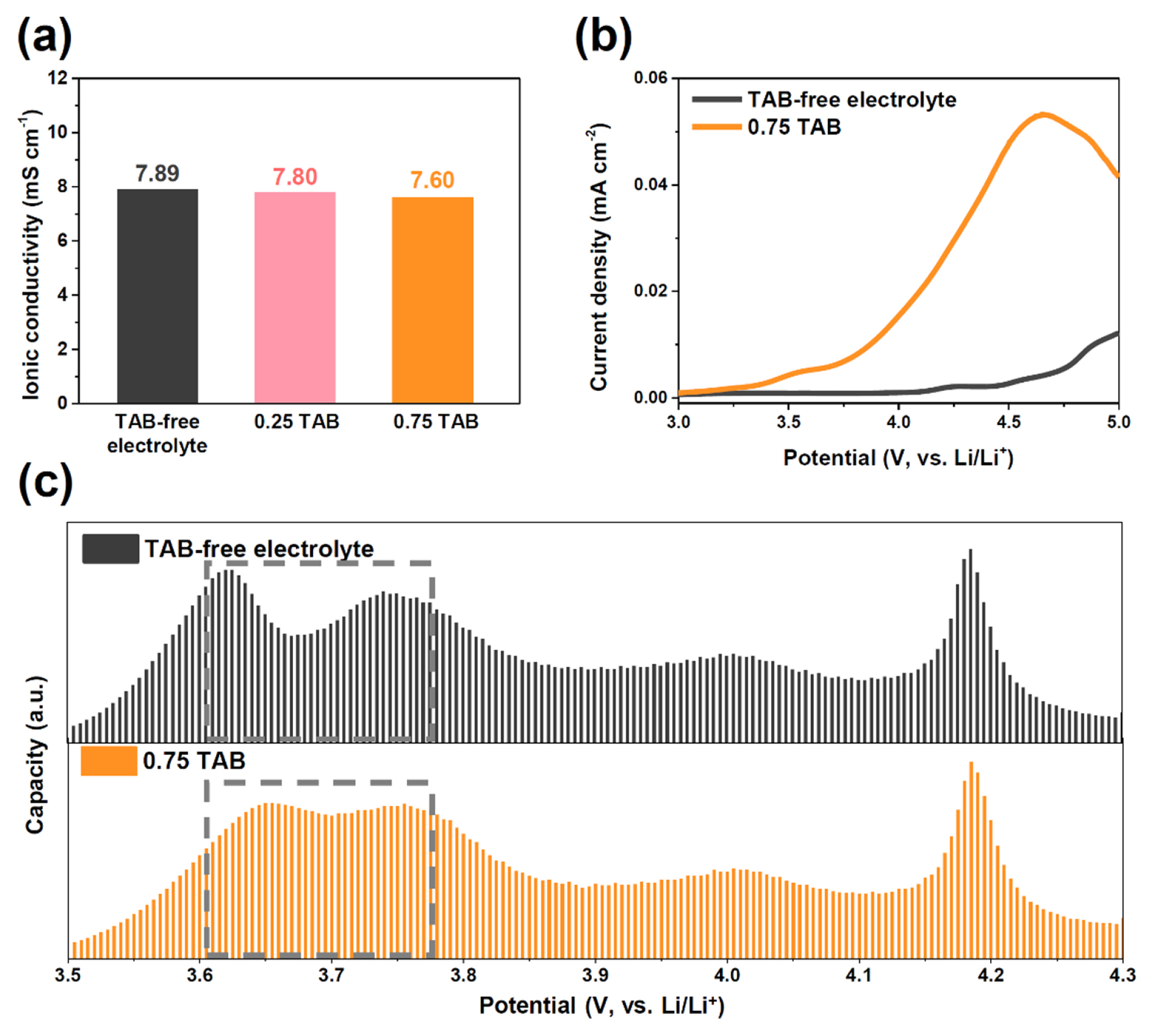
(a) Ionic conductivity of TAB-free electrolyte (black) and TAB additive: 0.25 TAB (pink), 0.75 TAB (orange). (b) LSV results for TAB-free electrolyte (black) and 0.75 TAB (orange). (c) EVS results for TAB-free electrolyte (black) and 0.75 TAB (orange).
The CV test was used to elucidate the electrochemical properties of a LNCM83 cathode with the TAB additive (Fig. 3a,b). In the TAB-free electrolyte, the LNCM83 cathode appeared at an oxidation peak of 3.92 V (vs. Li/Li+) during the first cycle and 3.70 V (vs. Li/Li+) during the second cycle. In the cell tested by 0.75 TAB, the oxidation peak of Ni species was observed at 4.00 V (vs. Li/Li+) and 3.70 V (vs. Li/Li+) during the first and second cycles, respectively. The late observation of the Ni reaction in the TAB additive can be rationalized that once oxidation of TAB forms an additional layer on the LNCM83 cathode, it may increase the migration pathway for Li+ species at the interface of LNCM83 cathode and electrolyte, leading to a slightly increased polarization. These behaviors, however, were well resolved after one cycle, indicating that they increased interfacial resistance temporarily but not permanently. In terms of Li+ diffusion coefficient (DLi+, as measured by CV; Fig. 3c,f), the TAB additive had a slightly lower DLi+ value (2.87×10⁻⁹ cm2 s−1) than the TAB-free electrolyte (3.01×10⁻⁹ cm2 s−1). The slightly lower DLi+ value can be attributed to the relatively low ionic conductivity and slightly increased internal resistance caused by forming CEI layers. However, it is believed that it has little effect on cycling performance because the TAB-derived CEI layer effectively contributes to the prolonged cycling performance, as it is designed to inhibit electrolyte decomposition rather than to improve physical properties.
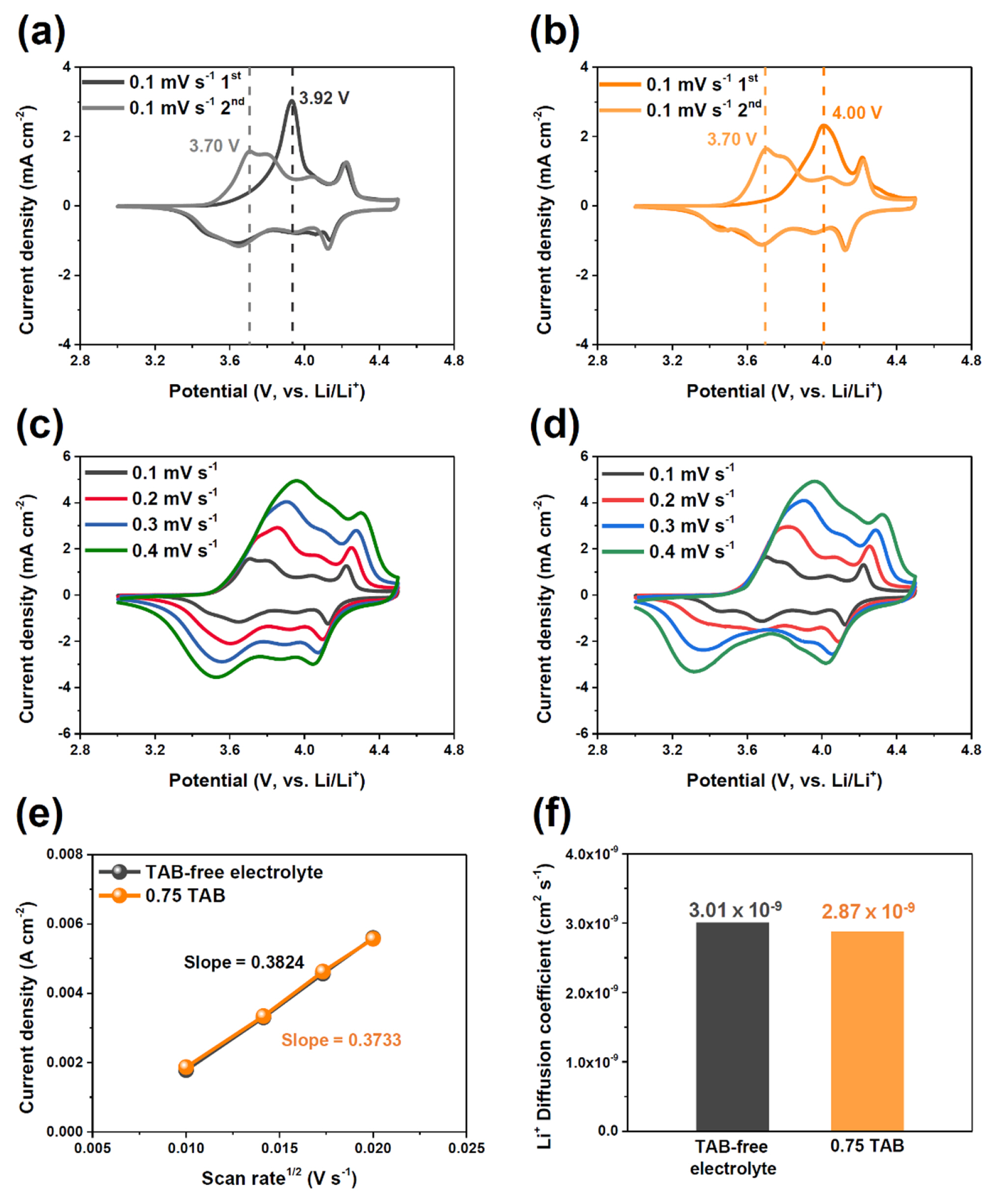
Cyclic voltammetry profile of (a) TAB-free electrolyte and (b) 0.75 TAB. Cyclic voltammetry profile at various scan rates (0.1–0.4 mV s−1) of (c) TAB-free electrolyte and (d) 0.75 TAB. (e) Linear slope of the peak current density as a function of the square root of scan rates and (f) calculated Li+ diffusion coefficients.
We evaluated the electrochemical performance of the TAB. At elevated temperatures, there were significant differences between cells with and without TAB additive (Fig. 4a,b). Initial cycling behaviors were nearly identical in potential profiles, regardless of the presence of the TAB additive in the cell. However, there was a notable change in cycling retention: When the cell was cycled without TAB, the retention was gradually decreased to 64.1% (137.3 mA h g−1). Otherwise, cells in the presence of the TAB additive demonstrated increased retention: 75.0% (160.0 mA h g−1 for 0.25 TAB), and 88.3% (187.0 mA h g−1 for 0.75 TAB), respectively. It was estimated that 0.25 wt% of TAB additive would be insufficient to form a uniformly distributed CEI layer on the LNCM83 cathode. In the recovery test (Fig. 4c,d), the TAB additive indicated improved electrochemical performance. In detail, we recovered the cycled LNCM83 cathode after 30 cycles, and the recovered LNCM83 cathode was used for evaluating rate capability. Because the surface of the tested LNCM83 cathode without TAB may have been covered by decomposed products from the decomposition of the main electrolyte components, it showed an apparently decreasing specific capacity. Otherwise, the recovered LNCM83 cathode with the TAB still delivered moderate specific capacity regardless of charge C-rate, indicating that the surface properties were notably improved by the use of the TAB additive in the cell. Additional DLi+ values obtained from the GITT analyses also supported these behaviors (Fig. 4e,f). In the first step, the TAB-free electrolyte showed relatively higher DLi+ values than the TAB additive in overall potential ranges because of its higher ionic conductivity in the cell (average DLi+ for TAB-free electrolyte: 2.05×10⁻⁸ cm2 s−1; for TAB additive: 1.81×10⁻⁸ cm2 s−1). However, it was reversed after 30 cycles (average DLi+ for TAB-free electrolyte: 9.49×10⁻⁹ cm2 s−1; for TAB additive: 1.62×10⁻⁸ cm2 s−1), as the TAB additive well stabilized the interfacial reactivity of the LNCM83 cathode. This indicated that the TAB can improve the interfacial stability of the LNCM83 cathode, because an additional CEI layer would efficiently prevent undesired reactions from occurring in the cycling.
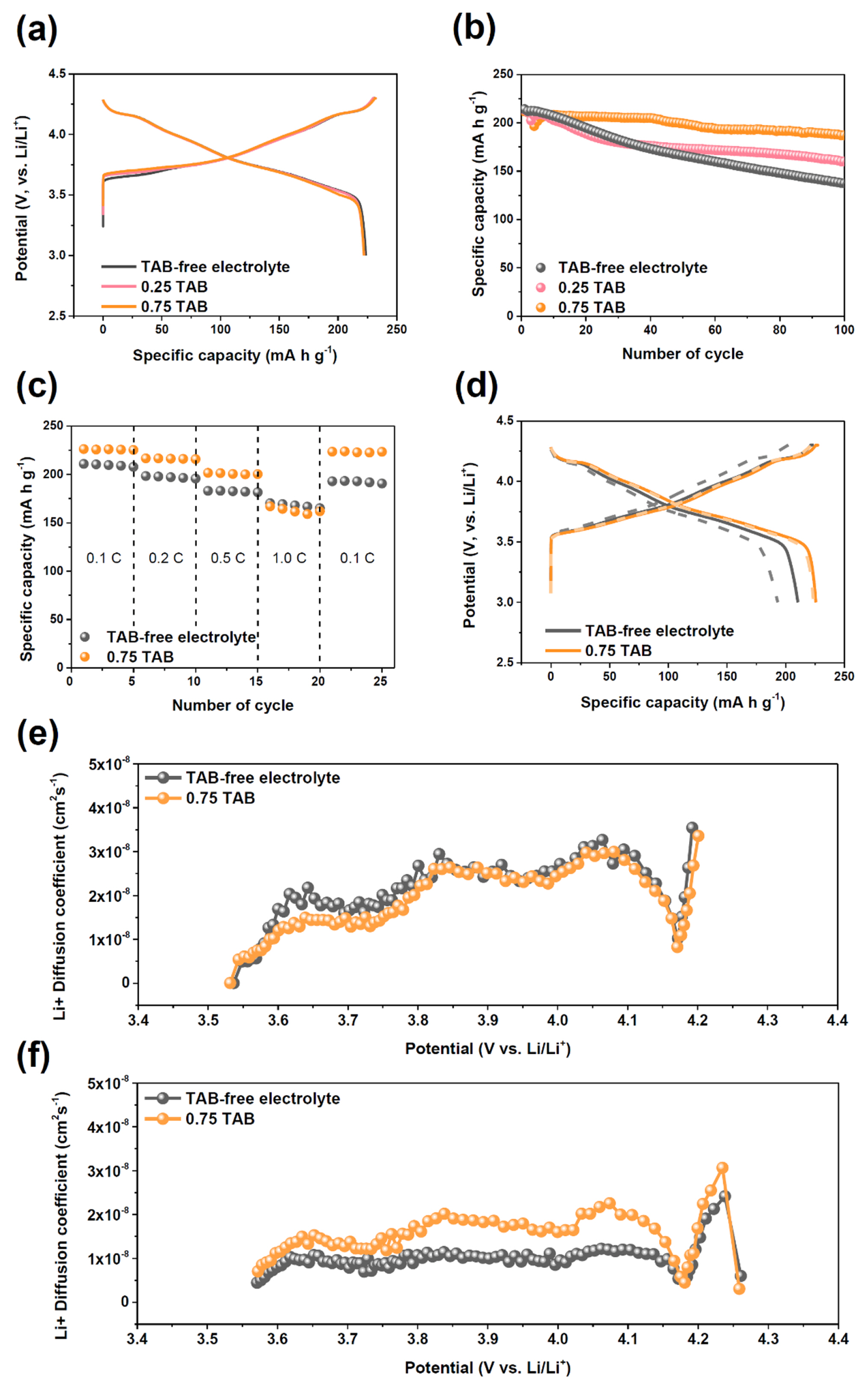
(a) Potential profiles in the initial cycle and (b) cycling performances at 45°C (black: TAB-free electrolyte, pink: 0.25 TAB, orange: 0.75 TAB). (c) Rate capability of the cells cycled with TAB-free electrolyte (black) and 0.75 TAB (orange) at 45°C. (d) Potential profiles of rate capability in initial 0.1 C (line) and recovery (dash) of 0.1 C. GITT results of TAB-free electrolyte and 0.75 TAB at (e) initial and (f) after 30 cycles.
To compare the surface state of each LNCM83 cathode, cycled LNCM83 cathodes were analyzed by SEM (Fig. 5a–d). After the formation cycle, the surface of the LNCM83 cathode tested by the TAB-free electrolyte was nearly identical. However, the forming of an island-type artificial CEI layer on the LNCM83 cathode cycled with the TAB additive was evident. After cycling, large amounts of decomposed products were found on the cathode cycled with the TAB-free electrolyte. It was hard to distinguish grain boundaries of the primary particles, indicating that electrolyte decomposition had occurred significantly in the cell. On the other hand, the LNCM83 cathode with the TAB illustrated an obviously distinct surface state: A relatively clean surface was observed in the SEM image, which is consistent with high temperature cycling results. In the XPS analyses (Fig. 5e), there were considerable differences in the recovered LNCM83 cathodes. In C 1s spectra, the recovered LNCM83 cathode cycled without TAB was mainly composed of Li2CO3 (288.8 eV) [43], C=O (287.4 eV) [44], and C–O (286.1 eV) [45], OCO2 (290.6 eV) [46], which are considered to be the main components from solvent decomposition upon cycling [47]. In contrast, LNCM83 cathode with TAB revealed lower intensity that cycled in the absence of TAB. In P 2p spectra, a much higher intensity of the LixPFy (136.3 eV) [48] and LixPOyFz (134.5eV) [49] was observed in the LNCM83 cycled without TAB. In F 1s, most of the peaks were commonly observed in the recovered LNCM83 cathode; however, the B–F peak was identified at 687.1 eV in the case of the recovered LNCM83 cycled with the TAB additive. It may be elucidated that once the B element participates in forming the artificial CEI layer, it can easily bind with F− species remaining in the electrolyte (side products obtained from electrolyte decomposition) and thereby appeared in the F 1s spectra. It means that the TAB-derived artificial CEI layer can be effective for decreasing F− components remaining in the cell via selective trapping reaction, leading to improved cathode stability.
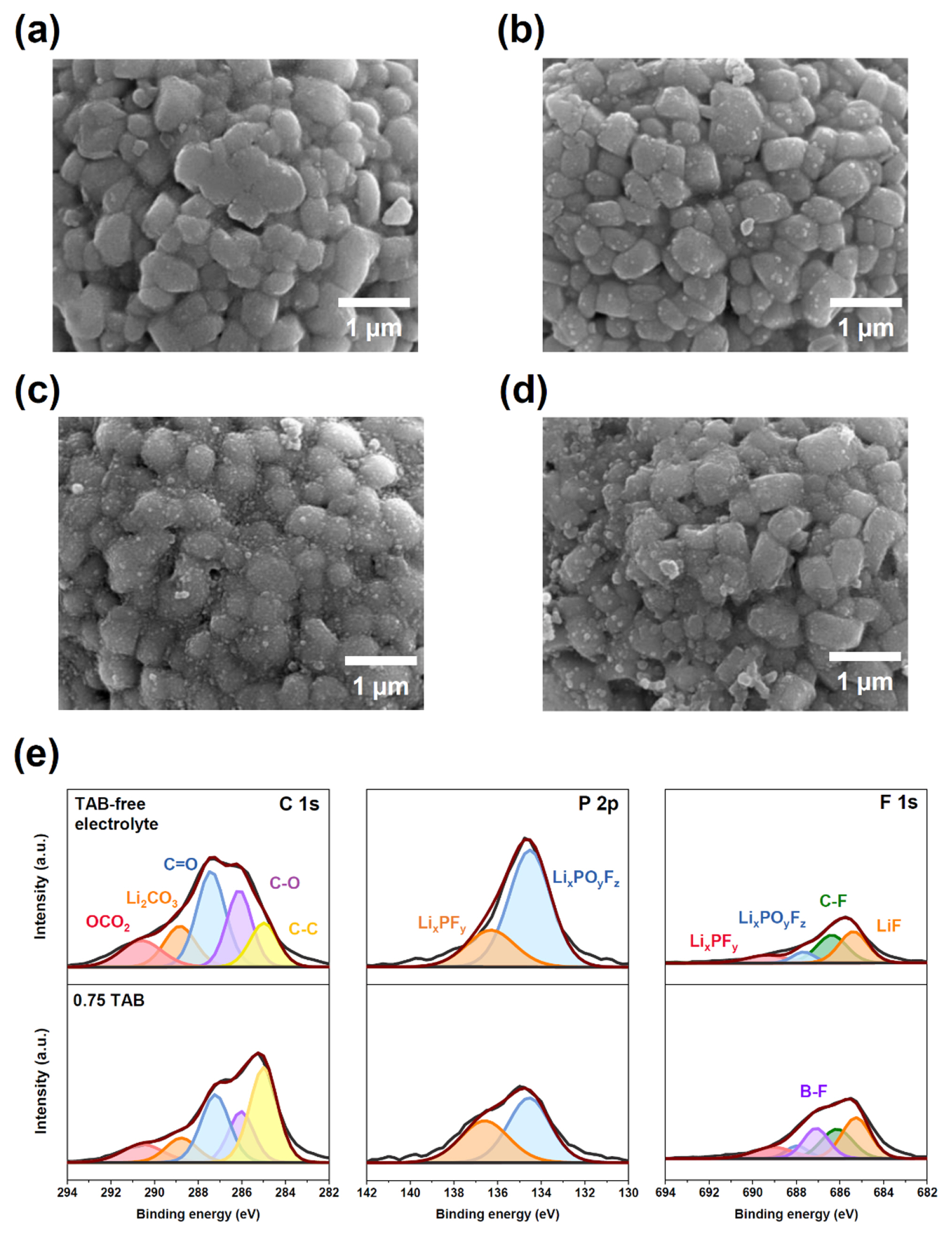
SEM images after first cycle with (a) TAB-free electrolyte and (b) 0.75 TAB. SEM images after 120 cycles with (c) TAB-free electrolyte and (d) 0.75 TAB. XPS spectra for cycled LNCM83 electrodes with (e) TAB-free electrolyte and 0.75 TAB: C 1s, P 2p, F 1s.
To verify the F− scavenging activity of the TAB, its chemical reactivity was elucidated using NMR for the resulting products obtained from a chemical reaction of the TAB additive with TBAF (equivalent to F−). In 1H-NMR spectroscopy (Fig. 6a–c), new peaks at 4.11 and 2.37 ppm, assigned to 1H peaks from allyl alcohol, were observed. These peaks can be produced chemically by reacting TAB with F− species. In 19F-NMR spectroscopy (Fig. 6d), the F peak at TBAF was observed at −129.0 ppm, but it was shifted to −138.4 ppm, which is in line with 1H-NMR spectroscopy. The reaction mechanism between TAB and F− was estimated, as illustrated in Fig. 6e. Because the boron element does not satisfy the octet rule, it is preferred to receive two electrons. In this case, F− addition to the B site occurs easily, and further F− substitution between TBAF and TAB results in allyl alcohol and fluorinated borate compounds that can be identified using NMR spectroscopy. In our additional ICP-MS analyses for recovered cells (Fig. 6f), meaningful results to support it were observed. In the cell cycled TAB-free electrolyte, there was a considerable amount of transition metal dissolution (6129 ppb), as none-captured F− species accelerated dissolution of transition metals from the LNCM83 cathode. On the contrary, dissolution of transition metals was remarkably decreased in the presence of the TAB additive, indicating that the TAB additive could help prevent transition metal components from dissolving in LNCM83 cathode by lowering the F− species remaining in the cell through a selective scavenging reaction.
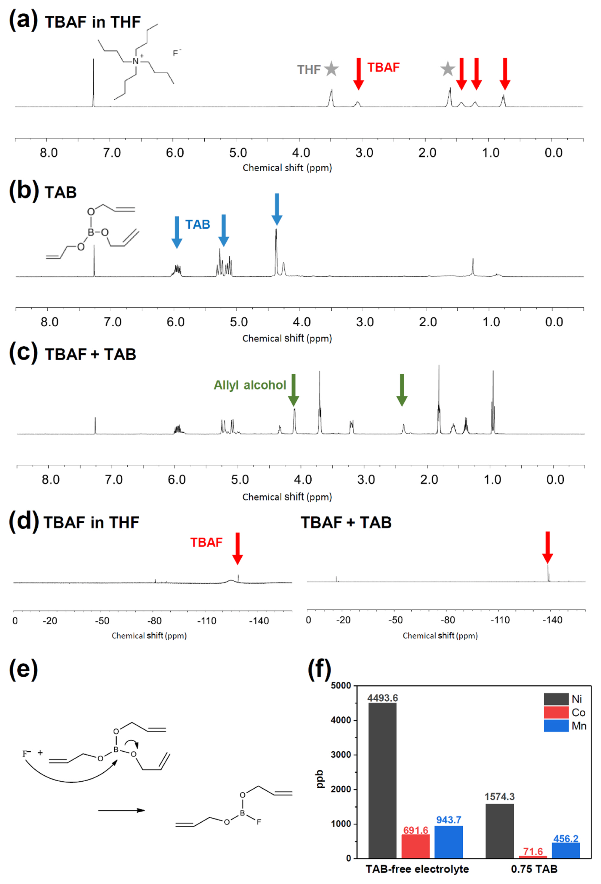
1H NMR spectra for (a) TBAF in THF, (b) TAB additive, and (c) solution after chemical reaction of TBAF and TAB. (d) 19F NMR spectroscopies for TBAF in THF (left) and supernatant reacted by TBAF + TAB (right). (e) Mechanism of TAB additive for HF scavenging reaction. (f) ICP-MS results for cycled anodes with TAB-free electrolyte and 0.75 TAB additive.
To verify the effectiveness of TAB, the LNCM83/graphite full-cells were assembled with TAB additive and its lifespan of the cells were evaluated at 45°C (Fig. 7a). In the initial cycle, the addition of TAB additive had no recognizable side effect on the lifespan of the full-cells. On the contrary, cycling behaviors of the full-cell with TAB additive was preferable to that without TAB additive after 130 cycles (TAB-free electrolyte: 89.6%, TAB-containing electrolyte: 96.4%). This is believed to be because the TAB additive forms CEI at the anode interface, and the formed CEI inhibits the continuously occurring electrolyte decomposition as well as dissolution of transition metals. In the SEM analyses for the cycled cathode and separator, it was found that there was a morphological difference between recovered LNCM83/separator interfaces depending on the TAB additive (Fig. 7a–d). In the recovered LNCM83 cathode without TAB, the surface of the LNCM83 cathode seemed to be covered by decomposed adducts from electrolyte decomposition. On the contrary, the relatively clean surface morphology of cycled LNCM83 was observed in the case of TAB use, indicating electrolyte decomposition was well suppressed during full-cell cycling. In the separator analyses, pores of the separator without TAB seemed to be blocked by accumulating decomposed adducts on the separator. In contrast, the cycled separator with TAB exhibited surface morphology similar to its own structure. From this result, it could be concluded that TAB can be applicable to the full-cells with LNCM83 cathodes.

(a) Lifespan of LNCM83/graphite full-cells at 45°C. SEM images for cycled LNCM83 cathodes: (b) without TAB, and (c) with TAB, and separators: (d) without TAB, and (e) with TAB.
4. Conclusions
TAB, an allyl- and borate-functionalized material, has been suggested as a functional additive to increase the interfacial stability of LNCM83 cathode materials. From ex-situ NMR analysis, TAB can selectively remove F− species through scavenging reaction, and it leads to improving surface stability of LNCM83 cathode via inhibiting the dissolution of transition metal components. Additionally, by electrochemical oxidation at 3.7 V (vs. Li/Li+), the TAB additive can form a borate-based CEI layer on the LNCM83 cathode. Both TAB-free electrolyte and TAB additive exhibit similar cycling retention behaviors at room temperature. On the other hand, the cells cycled with TAB additive demonstrated improved retention at elevated temperatures; cells cycled with 0.75 TAB showed the highest retention ratio (88.3%) whereas those cycled without TAB revealed only 64.1% of retention. Additional systematic analyses, including SEM, XPS, and ICP-MS, consistently indicated that TAB effectively inhibits electrolyte decomposition during electrochemical cycling once it forms CEI layers on the LNCM83 cathode. As a result of these findings, it can be concluded that a combination of the TAB additive with the LNCM83 cathode improves interfacial stability by inhibiting electrolyte decomposition and lowering F− species in the cell, thereby dramatically improving electrochemical results. Therefore, the LNCM83/graphite full-cell cycled with TAB revealed increasing retentions due to enhancing the stability of electrode surfaces compared to that cycled without TAB.
Acknowledgements
This work was supported by the National Research Foundation of Korea (NRF) (NRF-2022R1F1A 1069039 and 2017R1A6A1A06015181), and the Technology Innovation Program (20011905) funded by the Ministry of Trade, Industry & Energy (MOTIE, Korea).