The Operation of Polymer Electrolyte Membrane Fuel Cell using Hydrogen Produced from the Combined Methanol Reforming Process
Article information
Abstract
A combined system with PEMFC and reformer is introduced and optimized for the real use of this kind of system in the future. The hydrogen source to operate the PEMFC system is methanol, which needs two parts of methanol reforming reaction and preferential oxidation (PROX) for the hydrogen fuel process in the combined operation PEMFC system. With the optimized methanol steam reforming condition, we tested PROX reactions in various operation temperature from 170 to 270 ℃ to investigate CO concentration data in the reformed gases. Using these different CO concentration, PEMFC performances are achieved at the combined system. Pt/C and Ru promoted Pt/C were catalysts were used for the anode to compare the stability in CO contained gases. The alloy catalyst of PtRu/C shows higher performance and better resistance to CO than the Pt/C at even high CO amount of 200 ppm, indicating a promotion not only to the activity but also to the CO tolerance. Furthermore, in a system point of view, there is a fluctuation in the PEMFC operation due to the unstable fuel supply. Therefore, we also modified the methanol reforming by a scaled up reactor and pressurization to produce steady operation of PEMFC. The optimized system with the methanol reformer and PEMFC shows a stable performance for a long time, which is providing a valuable data for the PEMFC commercialization.
1. Introduction
Fuel Cell Vehicles are achieving energy efficiencies of 40 to 50 percent in current road tests compared to 10 to 16 percent in conventional vehicles. Fuel cell vehicle can have twice as efficient at least than advanced vehicle like gasoline/battery hybrids [1]. Most of studies for on-board hydrogen production for fuel cells are based on two types of carbon compounds. One is oxygen-containing compounds, methanol, ethanol and etc. The others are hydrocarbons such as ethers (dimethylether, etc), natural gas, propane gas, gasoline, jet fuel and diesel fuel. Automotive Polymer Electrolyte Membrane Fuel Cell (PEMFC) requires hydrogen gas to operate. The most convenient way to obtain the gas would be to use an on-board fuel processor to convert or reform commonly available liquid fuels, such as gasoline, methanol, and ethanol, into hydrogen.
One of the major challenges to PEMECs system for vehicle has been the low tolerance to carbon monoxide on the fuel cell anode. For conventional fuel cells, the carbon monoxide levels need to be below 10 ppm, which in turn requires the use of additional reactors, such as water-gas shift(WGS) and preferential oxidation(PROX), or membrane purifier [2,3]. Compared to processor using higher hydrocarbon fuels, methanol processor has an advantage [7]. Their product stream often contains 1 % or less CO on a dry gas basis. In that case, the WGS reactors can be eliminated. However, further clean-up using either a membrane or PROX reactor is still required, these additional reactors increase the size and complexity of the reformer system while often lowering the efficiency [8-10].
The PROX catalyst should ideally exhibit both activity and selectivity toward CO oxidation in the presence of H2. Reported catalysts used for the selective oxidation of CO in presence of H2 are predominantly based upon either supported noble metals or mixed metal oxides [12]. The use of noble metals such as platinum, palladium and ruthenium is favorable from the viewpoint of their high activity and selectivity for CO oxidation in the temperature range up to 200 ℃ [9]. The high activity and selectivity of the catalysts arises from the strong preferential binding of CO over H2. Additionally, any reduction in the precious metal requirement via either promotion or substitution with suitable transition metals would be beneficial regarding cost [9]. CuO-CeO2 catalysts have been shown to be very active for CO oxidation in hydrogen rich gas without using precious metals. The mixedoxide catalysts were better than other catalysts like the conventional copper-based and platinum, palladium and ruthenium in terms of activity and selectivity [8].
The fuel processing system consists of a steam reforming catalyst layer which converts methanol and water to a hydrogen-rich gas as illustrated in equation (1) and CuO-CeO2 catalyst layer for preferential CO oxidation to remove the 0.5~0.8 % of carbon monoxide present in the reforming gas to below 10 ppm shown in equation (4) [4-6].
Methanol steam reforming


Preferential oxidation


In this study, we demonstrate a PEMFC system with methanol fuel process that is mainly composed by two parts of methanol reforming reaction and preferential oxidation (PROX). The optimized operation conditions such as temperature were investigated for these two parts at the methanol fuel process system. Furthermore, the combined system with PEMFC was evaluated by various operation conditions and catalysts to study the enhancing efficiency and stability of the system, which could be a valuable data for the fuel cell commercialization.
2. Experimental Section
2.1 Reforming system
Two parts of the reforming system were designed to produce hydrogen and reduce CO, as shown in Fig. 1. First, methanol and water for a steam reforming was fed into the reformer reactor under the commercial catalyst of ICI 33-5 as a MeOH reforming catalyst. Table 1 shows chemical composition and physical properties of ICI 33-5. For the beginning system, 1 g of ICI 33-5 catalyst with a particle size of 40-50 mesh was packed into a 1/4 inch stainless steel reactor. Before the MeOH reforming reaction, the catalyst was reduced under H2 for 2hr. A pump (FMI LAB PUMP, Model QG 150) supplied the mixture of methanol and water (molar ratio 1:2) to the vaporizer with a liquid MeOH flow rate of 0.1 mL/min [7]. In the modified system, 4 g of ICI 33-5 catalyst of same size was packed into a bigger 1/2 inch stainless reactor. The catalyst was also reduced under H2 for 2 h. A pump (Syringe Pump, Model KDS200) supplied the mixture of methanol and water (molar ratio 1:2) to the vaporizer with a liquid MeOH flow rate of 0.08 ml/min. The vapor was reacted inside of reformer and the reactor generated a hydrogen rich stream.

The schematic diagram of PEMFC with fuel process.

Properties of ICI 33-5 reforming catalyst
For the preferential oxidation, 20 % CuO-CeO2 catalysts were prepared by co-precipitation, the precursor salts of Cu(NO3)2•3H2O and Ce(NO3)3•6H2O, were dissolved in deionized water, mixed together and heated to 70 ℃. NaOH solution was added drop wise to precipitate the metals as hydroxides under vigor us stirring and the precipitate was aged with stirring at 70 ℃ for 5 h. The pH of the mixed solution was kept at 10. The precipitate was filtered and washed with deionized water to remove the residual sodium, and then dried for 12 h at 90℃. The dried precipitate was calcined at 500 ℃ for 5 h in air. The calcined catalyst was crushed and sieved to 0.15-0.18 mm. The BET surface area of the catalyst was 91 m2/g. The Cu content in the catalyst was designated as Cu/(Cu+Ce) atom ratio100 (at%) [8]. The reaction experiments were carried out in a 1/4 inch stainless steel tube reactor at normal pressure. 3 g of 20 %CuO-CeO2 catalyst of 80-100 mesh size was used. A K-type thermocouple was placed at the center of the bed to monitor the reaction temperature.
2.2 PEMFC system
The PEMFC system was operated by the reactant from the fuel processor composed of methanol reformer and preferential oxidation reactor, as shown in Fig. 1. The PEMFC performance was tested with a single cell (25 cm2) module. The MEA (Membrane Electrolyte Assembly) was prepared by a procedure of spraying and hot-pressing. Two different catalyst system were tested to find the best option. One is 20 % Pt/C (E-Tek, commercial catalyst) for both the anode and cathode catalysts, and the other is the catalysts of 20 % PtRu/C for anode and 20 % PtCoCr/C for cathode, which have been prepared by previous methods [9-12]. All of the catalysts were directly sprayed on the Nafion© 117 membrane (DuPont) with a loading of 0.2 mg/cm2 Pt. The MEA (Membrane Electrolyte Assembly) was prepared by hot-pressing at 248 °F for 90 sec. The operating temperature and pressure of the fuel cell were 80℃ and 1 atm, respectively. The reformed gases were fed into the anode and pure O2 was used in the cathode to provide a same reaction condition.
3. Results and Discussion
3.1 Methanol reforming reaction and Preferential oxidation of CO
For the first part of the reforming system, Fig. 2 shows the MeOH conversion with respect to the reaction temperature. The mixture of methanol and water was fixed with the molar ratio of 1:2 to compare the effect of the reaction temperature. From different groups, the effect of the water content in the feed on the methanol conversion was studied by Kim [7] and Jiang et al. [13,14]. When the water to MeOH ratio was changed from 1 to 2, there was no great difference in MeOH conversion as observed by Jiang [13,14]. Therefore, it was concluded that the reforming rate is not affected by water partial pressure as long as the partial pressure exceeds the methanol partial pressure. Using this optimized water and methanol molar ratio, the MeOH conversion drastically increased with increasing temperature from 170 ℃ and attained 100 % conversion from above 250 ℃. At this condition, it generated 55 % of hydrogen, 18 % of carbon dioxide, 0.2 % of carbon monoxide and 26.8 % of water with a conversion of 100 % at the reaction temperature of 250 ℃.

MeOH conversion with respect to reforming temperature using ICI 33-5 catalyst.
Fig. 3 shows CO conversion with increasing temperature for the second part of preferential oxidation of CO for the reformer. The air-to-CO ratio was fixed to the value of 1.5 that is known as the most effective region [8-9]. By focusing only on the effect of the temperature, it was found that the CO concentration is decreased especially from the reaction temperature of 170 to 200 with the value range of 200 ppm to 10 ppm. As a result, when the reaction temperatures of the preferential oxidation of CO were 170, 180, 190 and 200 ℃, the CO concentrations were 200 ppm, 70 ppm, 30 ppm and 10 ppm, respectively. The 20 % CuO-CeO2 catalyst reduced the amount of CO to less than 10ppm at the very high reaction temperature of 190-200 ℃. It shows the preferential oxidation of CO needs more amount of O2 than the theoretical stoichiometry. In addition, hydrogen oxidation was also suppressed in parallel with CO oxidation which required high temperature operation of PROX reaction.

Conversion of CO in reformate gas with PROX reaction temperature using 20% CuO-CeO2 catalyst.
3.2 PEMFC operation with reformer
After the optimization of the operation condition of the reformer, the effect of CO concentration on the PEMFC operation was investigated by the different concentration of CO in the reformer gas of the fuel processor, which was made by changing the operating con dition of the PROX reactor. Two different catalysts systems were evaluated by the PEMFC single cell tests.
Fig. 4(a) shows the single cell performance of commercial Pt/C catalyst at both electrodes with changing CO concentration in the reformed gas. As we can expect, the PEMFC performance decreases when the concentration of CO increases. Almost 90 % of the performance decrease was shown while the CO concentration was increased to 200 ppm due to the CO poisoning to the Pt catalyst. The impedance measurement was carried out at 80 ℃ by feeding oxygen in the cathode side and the reformer gas into anode side. Fig. 4(b) illustrates the impedance spectra of Pt/C with various CO concentration and H2 gas. Membrane resistance and interfacial resistance were increased by CO in reformate gas, as listed in Table 2. Interfacial resistance was increased drastically from 30 ppm of CO This is due to preferential adsorption CO on Pt catalyst compared to hydrogen, which acts as a poison on the catalyst. On the other hand, as shown in Fig. 5(a), although the different catalyst system of PtRu/C for anode and PtCoCr/C for cathode demonstrations similar PEMFC performance, a better resistance to the CO was shown for these alloy catalysts from the smaller decrease of the performance with the value around 75 % at the CO concentration of 200 ppm. Impedance spectra of PtRu/C with CO is also shown in Fig. 5(b). MEA interfacial resistance using PtRu/C catalyst was slightly reduced at all range of CO concentration with CO which is also summarized in Table 2. It is the reason that the PtRu/C catalyst has not only a better activity but also more tolerance on the CO gas, which provides a promising properties in our system. As we can concluded, the catalytic activity of pure Pt/C was higher than that of PtRu/C for pure hydrogen. However, in a view of practiced application, PtRu/C as an anode catalyst seems to be more beneficial because of CO generated in reformatted gases to ensure the stability of integrated operation of PEMFC with fuel processor.

The (a) performance and (b) impedance study of the PEMFC with Pt/C at anode/cathode as a function of CO concentration.
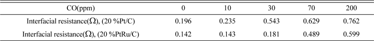
Interfacial resistance of MEA about various CO concentration

The (a) performance and (b) impedance study of the PEMFC with PtRu/C (anode) and PtCoCr/C (cathode) as a function of CO concentration.
For this combined system, we found a problem of the unstable performance during the reproducibility tests. Fig. 6 (a) shows the PEMFC performance at every 4 min operated by MeOH reforming system which generates hydrogen containing 10ppm CO. Unstable performance of the PEMFC was revealed at atmosphere operation for different operation times. Since the PEMFC system has reformer to supply reformed gas, the reactant fuel gases should have no back pressure to overcome that of gases head built into the reformer. With the back pressure in the reforming system, the flow rate in the inlet of PEMFC can be very unstable, since the reactant flows into the reactor by pulses. When the flow rate of fuel gas was unstable, the performance of PEMFC was simultaneously fluctuated as shown in the operation at atmospheric in Fig. 6(b).

The flow fluctuation on the fuel cell performance at (a) every 4 min and (b) during 24 min.
3.3 System optimization and long-term tests
In order to overcome the fluctuation, the system modification of the fuel gas PEMFC operation has been attempted. The system was scaled up and the pressure maintained by the high pressure pump with pressure regulator. With this modified system, we can obtain a stable PEMFC performance of 630 mA/cm2 in Pt/C, and 717 mA/cm2 in PtRu/C at 0.6 V, which is similar to the previous performance, as shown in Fig. 7 about the performance of catalysts on PEMFC operation with the new fuel processor.

Performance of PEMFC with Pt/C and PtRu/C for each anode catalysts at the modified PEMFC and reformer combined system.
Fig. 8(a) shows PEMFC long term stability tests with the different MeOH reforming reactors to display the enhancement of the system. For the previous system, we can see the fluctuation with a low performance of fuel cell between 1200 and 2400 minutes, due to the fluctuating flow rate from methanol steam reformer which may be for the recharging of the liquid feed and changing other process parameters. This was avoided by using large a storage tank for methanol fuel for the modified system. After changing the system, the performance lased with a stable long time operation (Fig. 8(b)), indicating the optimization of the PEMFC and fuel processor combined system. This results can provide a valuable data for the commercialization of this kind of system from this advanced study.

Long term stability performance of PEMFC with MeOH reforming process for (a) the original system and (b) modified system.
4. Conclusion
We exhibit a systemically designed combination of PEMFC and methanol fuel process to reveal an enhanced system for the PEMFC commercialization. The fuel processing system is operated to generate hydrogen in situ from a methanol-water mixture for the PEMFC operation. The MeOH conversion attained 100 % at 250 ℃ and it converts to mixture gas consist of hydrogen(rich), water vapor, carbon monoxide, carbon dioxide. The PROX system with the 20 % CuO-CeO2 catalyst completely oxidized the CO concentration to less than 10 ppm at 180-200 ℃. By operating the PEMFC, the membrane and interfacial resistance increased as increasing CO concentration and it drastically decreased the performance. We found that the PtRu/C catalyst was beneficial to continue the highly active and stable operation of PEMFC with fuel processor under the certain amount of CO in the reformed gas. To overcome violently unstable flow rate in the inlet of PEMFC due to the pressure drop in reactor, modified reformer system was also introduced to make a stable PEMFC performance. Finally, we could demonstrate our developed system (PtRu/C: anode, PtCrCo/C: cathode) for the methanol reformer and PEMFC, which showed high performance and stability.
Acknowledgements
This research was supported by the Industrial Technology Innovation Program funded by the Ministry Of Trade, Industry and Energy (MOTIE), Republic of Korea (grant number 10052076 and 10052823)
References
S. Fable and S. Unnasch, Fuel Cell Reformer Emissions, DOE Hydrogen, Fuel Cells and Infrastructure Technologies Annual Review Presentation, (2004).
Fable S., Unnasch S.. Fuel Cell Reformer Emissions In : DOE Hydrogen, Fuel Cells and Infrastructure Technologies Annual Review Presentation; (2004).E. R. Delsman, M. H. J. M. DeCroon, A. Pierik, G. J. Kramer, P. D. Cobden, Ch. Hofmann, V. Cominos and J. C. Schouten, Chem. Eng. Sci., 2004, 59, 4795-4802.
Delsman E. R., DeCroon M. H. J. M., Pierik A., Kramer G. J., Cobden P. D., Hofmann Ch., Cominos V., Schouten J. C.. Chem. Eng. Sci. 2004;59:4795–4802. 10.1016/j.ces.2004.07.099.J. D. Holladay, J. S. Wainright, E. O. Jones and S. R. Gano, J. Power Sources, 2004, 130, 111-118.
Holladay J. D., Wainright J. S., Jones E. O., Gano S. R.. J. Power Sources 2004;130:111–118. 10.1016/j.jpowsour.2003.11.055.J. R. Lattner and M. P. Harold, Appl. Catal. B: Environ., 2005, 56, 149-169.
Lattner J. R., Harold M. P.. Appl. Catal. B: Environ. 2005;56:149–169. 10.1016/j.apcatb.2004.06.024.M. Krumpelt, T. R. Krause, J. D. Carter, J. P. Kopasz and S. Ahmed, Catal. Today, 2002, 77, 3-16.
Krumpelt M., Krause T. R., Carter J. D., Kopasz J. P., Ahmed S.. Catal. Today 2002;77:3–16. 10.1016/S0920-5861(02)00230-4.S. K. Kamarudin, , W. R. W. Daud, A. Md. Som, M. S. Takriff, A. W. Mohammad and Y. K. Loke, Chem. Eng. J., 2004, 104, 7-17.
Kamarudin S. K., Daud W. R. W., Md. Som A., Takriff M. S., Mohammad A. W., Loke Y. K.. Chem. Eng. J. 2004;104:7–17. 10.1016/j.cej.2004.07.007.J. K. Lee, J. B. Ko and D. H. Kim, Appl. Catal. A Gen., 2004, 278, 25-35.
Lee J. K., Ko J. B., Kim D. H.. Appl. Catal. A Gen. 2004;278:25–35. 10.1016/j.apcata.2004.09.022.D. H. Kim and J. E. Cha, Catal. Letters, 2002, 86, 107-112.
Kim D. H., Cha J. E.. Catal. Letters 2002;86:107–112.C. D. Dudfield, R. Chen and P. L. Adcock, Int. J. Hydrogen Energy, 2001, 26, 763-775.
Dudfield C. D., Chen R., Adcock P. L.. Int. J. Hydrogen Energy 2001;26:763–775. 10.1016/S0360-3199(00)00131-2.O. Korotkikh and R. Farrauto, Catal. Today, 2000, 62, 249-254.
Korotkikh O., Farrauto R.. Catal. Today 2000;62:249–254. 10.1016/S0920-5861(00)00426-0.J.-D. Kim, Y.-I. Park, K. Kobayashi, M. Nagai and M. Kunimatsu, Solid State Ionics, 2001, 140, 313-325.
Kim J.-D., Park Y.-I., Kobayashi K., Nagai M., Kunimatsu M.. Solid State Ionics 2001;140:313–325. 10.1016/S0167-2738(01)00842-6.V. Recupero, L. Pino, M. Cordaro, A. Vita, F. Cipit편 and M. Laganà, Fuel Processing Tech., 2004, 85, 1445-1452.
Recupero V., Pino L., Cordaro M., Vita A., Cipit편 F, Laganà M.. Fuel Processing Tech. 2004;85:1445–1452. 10.1016/j.fuproc.2003.10.001.C. J. Jiang, D. L. Trimm, M. S. Wainwright and N. E. Cant, Appl. Catal. A Gen., 1993, 97, 145-158.
Jiang C. J., Trimm D. L., Wainwright M. S., Cant N. E.. Appl. Catal. A Gen. 1993;97:145–158. 10.1016/0926-860X(93)80081-Z.C. J. Jiang, D. L. Trimm, M. S. Wainwright, N. W. Appl. Catal. A Gen., 1993, 93, 245-255.
Jiang C. J., Trimm D. L., Wainwright M. S., . Appl. Catal. A Gen. 1993;93:245–255. 10.1016/0926-860X(93)85197-W.