Overview on Ceramic and Nanostructured Materials for Solid Oxide Fuel Cells (SOFCs) Working at Different Temperatures
Article information
Abstract
The article provides information on ceramic / nanostructured materials which are suitable for solid oxide fuel cells (SOFCs) working between 500 to 1000°C. However, low temperature solid oxide fuel cells LTSOFCs working at less than 600°C are being developed now-a-days with suitable new materials and are globally explored as the “future energy conversion devices”. The LTSOFCs device has emerged as a novel technology especially for stationary power generation, portable and transportation applications. Operating SOFC at low temperature (i.e. < 600°C) with higher efficiency is a bigger challenge for the scientific community since in low temperature regions, the efficiency might be less and the components might have exhibited lower catalytic activity which may result in poor cell performance. Employing new and novel nanoscale ceramic materials and composites may improve the SOFC performance at low temperature ranges is most focused now-a-days. This review article focuses on the overview of various ceramic and nanostructured materials and components applicable for SOFC devices reported by different researchers across the globe. More importance is given for the nanostructured materials and components developed for LTSOFC technology so far.
Abstract
Graphical Representation
1. Introduction
The present generation is facing energy demand due to increased population, which directs the scientific community to work for the development of advanced materials for meeting up the existing energy demands. The fossil fuel supplies are persistently diminishing because of which there is a need for converting the available source of energy to utilizable one [1–4]. Fuel cells are most promising energy conversion systems in the upcoming green and sustainable energy storage industries. Over other energy conversion systems, fuel cells are most advantageous since they produce zero or very less emission especially greenhouse gases based on the fuel used. Fuel cells are generally classified based on the type of electrolytes and the operating temperature [5]. They are classified as follows based on the electrolyte. 1. Alkaline Fuel cell (AFC), 2. Phosphoric Acid Fuel cell (PAFC), 3. Polymer Electrolytic Membrane Fuel Cell (PEMFC) / Solid Polymer Fuel Cell (SPFC) / Proton Exchange Membrane Fuel cell (PEMFC), 4.Molten Carbonate Fuel Cell (MCFC) and 5. Solid Oxide Fuel Cell (SOFC). The general characteristics and performances of different types of fuel cells are indicated in Table 1.

SOFC’s are more efficient than other types of fuel cells. The components of SOFC are made of non-precious ceramics which help SOFC to withstand very high temperature [5]. Since SOFCs operate at high temperature, there is a minimal need for precious metals and therefore cost is reduced. The cells need not be designed like plate as in other fuel cells since it employs solid electrolytes. They cannot be poisoned by carbon monoxide (CO), which can even be used as fuel. SOFCs have high level of fuel flexibility. Other than power generation, the high temperature operation of SOFC provides a way for waste heat utilization in domestic and industrial applications.
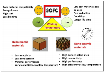
The conventional SOFC system is illustrated in Fig. 1. A SOFC stack constitutes an anode, a cathode and a solid electrolyte which is stacked by interconnecting materials in which anode of one stack is connected to cathode of other stack which is a conductor. As shown in Fig. 1, to operate the SOFC, hydrogen or hydrogen rich fuel is supplied to anode compartment and oxygen is supplied to the cathode compartment simultaneously at the operating temperature. At cathode compartment, O2 reduces to O2− ions and penetrate through the electrolyte to the anode compartment. The O2− ions combine with hydrogen gas at the anode and release the free electrons that flow through the external circuit to produce electricity. The anode and cathode materials should have proper electronic conductivity, the electrolyte material should have proper oxide ion conductivity and also all these three components should have compatible thermal expansion coefficient values with each other which will decide the overall performance of SOFC systems [6,7]. SOFC can be categorized into three types based on working temperature. The SOFC working at 900 to 1000°C is called as high temperature SOFCs. Due to the development of new materials, SOFC operating in the temperature range of 800°C has been emerged and termed as intermediate SOFC (IT-SOFC). Present day research is focused towards finding new materials in order to reduce the operating temperature of SOFC to around 600°C and which is termed as low temperature SOFC (LTSOFC). Lowering the operating temperature of SOFC reduces the conductivity of materials which is an issue between reducing the operating temperature and increasing the performance of these devices. Developing LTSOFC can reduce the cost, material degradation and life of the system [8].

Schematic illustration of working of Solid Oxide Fuel Cell (SOFC).
In recent years, the nanostructured ceramic materials (NSCMs) with <100 nm have been widely used in catalysis, thermal barrier coatings, solid electrolytes for fuel cells etc. NSCMs have good refractory properties, chemical and mechanical resistance in both normal and high temperature regions. They exhibit excellent sintering characteristics. The chemical methods which are used to synthesize NSCMs are sol-gel process [9], chemical precipitation [10], combustion [11], and others. The NSCMs are being recommended for SOFC applications especially to overcome the problems relevant to conductivity, chemical compatibility, thermal stability, etc. Nanomaterials and composites have considerable influence on minimizing the operation temperature of SOFC device with excellent electro-catalytic properties [12]. Nanostructured Sm doped CeO2 based electrolytes have exhibited improved mixed ionic conductivity for SOFC working at low temperature [13]. The enhancement of conductivity in components made by nanosized materials is mainly due to the grain boundary conductivity because of faster diffusion of ions in nanosized materials than in bulk materials [14]. The overall performance of SOFC is not dependent on individual electrodes and electrolyte materials alone however; it depends on all the components of SOFC. Each component of SOFC has its own contribution in enhancing the overall performance [15]. The ion transfer across or along the boundaries of solid ceramic components made by nanosized materials is found to be greater [16]. Keeping this in mind, this article reviews the characteristics of various materials (including nanoceramic materials) employed as electrolyte and electrode components in SOFCs. The chemistry of triple-phase boundary reactions and fuel choices for SOFC are also discussed in this review article.
2. Efficient cathode materials for SOFC
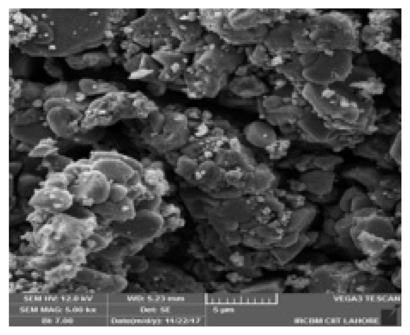
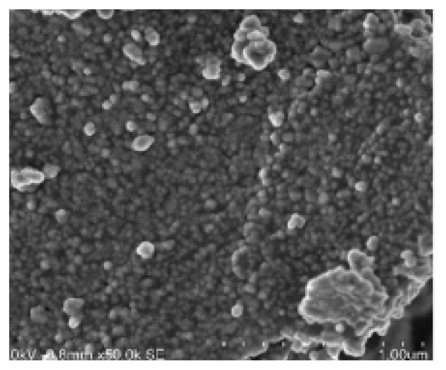
The cathode provides a platform for oxygen reduction reaction (ORR). To work as ORR site, the cathode should meet up some requirements which are discussed below: a) High electronic conductivity (more than 100 Scm−1 if possible) under oxidizing atmosphere, b) Thermal expansion coefficient (TEC) values should be in par with electrolyte and interconnecting material, c) Pervious to disperse oxygen gas through the cathode and cathode /electrolyte interface and d) Catalytically active to reduce the incoming oxygen and e) Less cost [17]. Ceramic perovskite based materials (general formula ABO3) are most commonly used as cathode in SOFC. They possess total net charge of +6 which includes both A and B cations. The structure and properties of perovskites are reported enough in literatures [18]. In perovskite based cathodes, the A-site cations are coordinated to 12 oxide ions. Mostly the A site cations are mixture of rare earths such as La, Sr, Ba, etc. and they often exhibit lower valency and higher ionic radius compared to B-site metals. The B site cations coordinated to 6 oxide ions. They are usually reported as mixture of reducible transition metals such as Fe, Co, Ni, Ti, etc. They exhibit higher valency and smaller ionic radii compared to A-site. Mostly the redox catalytic mechanism in cathode is provided by B-site cations. The octahedral symmetry around B site transition metals often provides a metallic semiconducting band structures at high temperature leading to high electronic conduction [19]. In perovskite based cathode, large and stable number of oxygen vacancies can be introduced by incorporating suitable dopants. This dopant incorporation, facilitate the ionic oxygen transport. The un-doped perovskites are poorly conducting whereas partially substituted A or B site cations with acceptor cations like Ca, Ba, Ti or the reducing cations lead to oxygen deficient perovskites [20]. Most studied perovskites are majorly relayed on manganites, ferrites, nickelates and cobaltites of lanthanides (L= Nd, Sm, La, Pr, etc.) with different substitutions in A and B sub lattices. These types of oxides provide excellent conductivity in LT-SOFC [21]. Conventional high temperature SOFC employs La1−xSrxMnO3−δ (LSM) and La1−xSrxCoO3−δ (LSC) as cathode materials [22]. By doping suitable metals in A and B sites of perovskites, we can improve the electrical conductivity and electro catalytic performance of cathode materials in SOFC [23]. Nanostructured ceramic perovskites are even more advantageous than the usual bulk perovskites in increasing the catalytic performances and conductivities [24]. Shao et al. [25] have studied the SEM micrographs (Fig. 2) of SrNbCoO3 − δ (SNC) and Ba0 . 5 Sr0.5Co0.8Fe0.2O3−δ (BSCF) cathode materials and inferred that the BSCF shows large particle size after sintering since it has large surface area where in SNC even though some larger particles are seen, presence of SNC grains with size of 0.5 μm dispersed on the surface of large particles increases the effective surface area of oxygen reduction reaction. This contributes much to improvement in performance of the SOFC. Jin et al. [26] have reported the double perovskites, LnBaCoFeO5+δ (Ln = Pr and Nd, PBCF and NBCF) as efficient cathode materials for ITSOFCs. LnBaCoFeO5+δ materials are found to be chemically compatible with La0.9Sr0.1Ga0.8Mg0.2O3−δ (LSGM) electrolyte at temperatures below 1000°C. PBCF and NBCF have exhibited the electrical conductivity 321 and 172 S cm−1 respectively at 350°C. Maximum power densities of the single-cell with Ni/SDC as anode on a 0.3 mm-thick LSGM electrolyte reached 749 and 669 mWcm−2 for PBCF and NBCF cathodes at 800°C, respectively. Abbas et al. [27] have prepared the La0.10Sr0.90Co0.20Zn0.80O5−δ (LSCZO) nanostructured cathode material by wet chemical route with crystallite size 47.55nm. LSCZO exhibited the electrical conductivity of 20.29 and 4.87 Scm−1 respectively in air and hydrogen atmosphere at the operating temperature of 550°C. The SEM image of LSCZO is represented in Fig. 3. It clearly shows that the synthesized LSCZO oxide material is porous and the grains are found in the range of 20–60 nm. List of different SOFC cathode materials and their performance characteristics is presented in Table 2. To gain a high electrocatalytic activity, the SOFC needs novel cathode materials that exhibit high performances. Many materials have already been used to make conventional SOFCs, such as perovskite-type oxides, fluorites, etc. Thus in recent years, perovskite based ceramic oxides were considered as better candidates for SOFC cathode materials. However, research activity is still going on to find out a suitable cathode component which can exhibit excellent catalytic performance at low temperature for the future generation [28].


SOFC cathode materials and their performance characteristics.
3. Efficient anode materials for SOFC
The prime role of anode in SOFC is to facilitate the fuel oxidation reaction and to conduct electrons to the external circuit [44]. SOFC anode should meet the following important requirements similar to cathode: a) Excellent electrical conductivity, b) Similar TEC values with other components of SOFC c) Good porosity (30%) for effective movement of gas molecules in high temperature reducing environment, d) Good catalytic characteristics over oxidation of fuel, e) Chemically and mechanically stable in reducible environment, f) Chemically inert to the fuel gases (H2, CO, and other hydrocarbons) and tolerate the carbon deposition, sulfur poisoning, reoxidation, etc.[45]. Initially Ni-YSZ cermet related materials were used as an anode for SOFC. Major drawbacks of the Ni-ceramic anodes are (1) changes in microstructure lead to affect the electrochemical activity; (2) evaporation of nickel under high steam concentration; (3) deposition of carbon in the anode when hydrocarbon is used as a fuel; (4) impurities such as sulphur and phosphor inhibit the functionality of anode; (5) nickel may tend to expand during re-oxidation process [46]. In order to overcome the above problems, materials viz., La0.9−xCaxCe0.1CrO3−δ [47], (La0.75Sr0.25)1−xCr0.5Mn0.5O3[48], Sr0.9La0.1TiO3 [49], Sr0.92Y0.08TiO3−δ [50], Y0.7Ca0.3Cr1−xCuxO3−δ [51], TiO0.2C0.8 [52], La0.65Ce0.1Sr0.25Cr0.5Mn0.5O3−δ, [53] etc. were proposed as anodes in SOFC. Yamamoto et al. [54] have prepared the NiO-GDC nanocube composite anode by an aerosol technique. The NiO-GDC nanocube composite anode with the enlarged TPB exhibited a low area specific resistance of 0.14 Ω cm2 compared with the conventional NiO-GDC composite anode’s resistance of 0.58 Ω cm2 when operated at 600 °C. Since the doped ceramics exhibit both ionic and electronic conductivities, there will be a chance of reduction in the performance of SOFC mainly due to excess electronic conductivity. To overcome this problem, nanocomposite based ceramic materials were proposed. Blennov et al. [55] have proposed Gd-doped ceria (CGO) in Nb doped SrTiO3 (STN) as a potential fuel electrode prepared by a novel surfactant-assisted infiltration process. Symmetrical cell measurements at open circuit voltage (OCV), showed that the electrochemical activity was maintained or even improved compared to Ni/YSZ fuel electrodes. The novel electrode had an electrode polarization resistance of 0.12 cm2 and 0.44 cm2 in humidified H2 at 850°C and 650°C, respectively. Abbas et al. [56] have demonstrated nanostructured Al0.10NixZn0.90−xO - Ce0.8Gd0.2O1.9 (ANZ-GDC) based anode for SOFC working at reduced temperature. The electrical conductivities (DC and AC) of the anodes were determined by four probe techniques and the values have been found to be 10.84 and 4.88 S/cm, respectively at hydrogen atmosphere in the temperature range of 300–600°C. The maximum power density of ANZ-GDC composite anode based solid oxide fuel cell has shown 705 mW/cm2 at 550°C. The SEM image of ANZ-GDC anode is presented in Fig. 4. The list of anode materials and their performance characteristics is reported in Table 3. However, suitable anode material can be chosen for LTSOFC applications based on its thermal and chemical compatibilities with the electrolyte material.


SOFC anode materials and their performance characteristics.
4. Efficient electrolyte materials for SOFC
Electrolyte is one of the major components is SOFC which is clubbed between the cathode and anode. The oxide ion reduced on the cathode side is moved through the electrolyte and reacts with hydrogen to form water as a byproduct and the electrons flows through the external circuit [65]. The electrolytes are categorized into (i) oxide ion conducting and (ii) proton conducting electrolytes among which oxide ion conducting are mostly preferred. To act as an effective electrolyte, it should meet up the following requirements: a) proper ionic conductivity without any significant electronic conductivity, b) stable under oxidizing and reducing environment and withstand at high temperature, c) impermeable to gas to prevent the mixing with fuel and oxidizer before they reach appropriate reaction sites and d) electronic conductivity should be nil in order to prevent leakage of current. Usually in SOFC electrolyte, solid ion conducting ceramics (SICC) were used for better ionic conductivity. There are two types of SICC 1) fluorite structured, and 2) perovskite structured. An interesting feature of the fluorite structure (MO2) is that it can sustain a high degree of substitution. As a result of high degree of substitution, a highly disordered material is formed which promotes ionic conduction. By substituting the host cation sites with either rare earth or an alkaline earth element, just as with yttria stabilized zirconia (YSZ), an increase of ionic conduction can be achieved. Yttria stabilized zirconia (YSZ), scandia stabilized zirconia (ScSZ) and gadolinium doped ceria (GDC) were most commonly used electrolyte in SOFC because of their excellent ionic conductivity. The fluorite type electrolytes having good oxide ion conductivity were arranged in the following order: Bi2O3>CeO2>ZrO2 [66]. YSZ undergoes strong interfacial reactions with the adjacent cathode materials (especially La1−xSrxMnO3 cathode) at elevated temperatures [67]. Further, YSZ is not recommended to be a favourable electrolyte material for SOFCs operating at low temperatures. The ionic conductivity of ScSZ is higher by almost five and nine times that of YSZ at 800 and 600°C, respectively. It was reported that a gadolinium-doped ceria (GDC) /scandia-stabilized zirconia (ScSZ) bilayer electrolyte has been used to avoid a compatibility problem between a perovskite cathode material and a stabilized zirconia electrolyte formation of the highly resistive La2Zr2O7 phase at the interface [68].
Nanostructured CeO2 is found to have more surface to volume ratio and hence it can show open structure which can result in more ionic conductivity. CeO2 doped with alkali or rare earth lanthanide metals can result in open structure which may further increase its ionic conductivity. However, the alkali earth metals are preferred over rare earth lanthanides as dopants nevertheless they are soluble in ceria [69]. Bi2O3 based materials have reported to possess highest oxygen ion conductibility at the operation temperature of SOFC. The oxygen ionic conductivity of Bi0.8Er0.2O1.5 and Bi0.85Nb0.15O1.65 at 600°C has been reported to be 3.7 × 10⁻¹ Scm−1 and 1.9 × 10⁻¹ Scm−1 respectively. At lower temperatures, however, a transformation of the δ-Bi2O3 phase into a rhombohedral phase and the formation of superstructures may lead to a sharp decrease in conductivity [70]. The conductivity of ABO3 perovskites strongly depends on the size of the ‘A’ and size of the ‘B’ cation, since the oxides have to migrate through a triangular space, consisting of two large ‘A’ cations and one smaller ‘B’ cation. The enlargement of this triangular space facilitates the migration of oxide ions through the lattice. Hence, higher ion conductivity is expected with larger lattice dimensions. Sr- and Mg-doped LaGaO3 (LSGM) is one of the encouraging electrolyte materials for SOFCs because of its good ionic conductivity and ionic transport number at intermediate temperature [71]. However, in order to avoid the reaction between Ni based anode and LSGM electrolyte, thin film of Sm2O3 doped CeO2 (SDC) was deposited between the anode and LSGM electrolyte [72].
The dopants for electrolyte component were selected based on the ionic radii of the metals. Lowering the operating temperature (to about 600°C) may reduce the ionic conductivity of the electrolyte and may affect performance of SOFC, because ionic conductivity is temperature dependent parameter. At elevated temperature the conductivity reaches to 1 Scm−1 due to the crystals that contains unoccupied sites equivalent to those occupied oxygen lattice ions and the energy for the total process is merely less than 1 eV [73]. The nanostructured ceramic based materials have significantly larger area of grain boundaries or interfaces. They help to improve the ionic conductivity of the electrolyte. Singh et al. [74] have reported a novel ceramic ceria electrolyte with the composition of Ce0.95AlLa0.05O1.9 with crystal size in the range of 40–55nm exhibiting excellent conductivity of 6.1×10⁻¹Scm−1. Sm0.2Ce0.8O1.9 (SDC)/Na2− CO3 nanocomposite electrolyte [75] exhibited an ionic conductivity of 0.1 Scm−1. This helps for direct utilization of methanol in LTSOFCs with the SDC/ Na2CO3 nanocomposite electrolyte. It resulted in a power density of 512 mW cm−2 at 550°C for fuel cell fueled by methanol. The SEM image of SDC/Na2− CO3 nanocomposite is represented in Fig. 5. Arshad et al. [76] have reported a new electrolyte Ce0.7Sm0.15Ge0.15O2−δ based on co-doped ceria nanocomposite, offering better performance for LTSOFCs. It showed a very good behavior at temperature 650°C where conductivity value reaches 0.074 Scm−1. Kannan et al. [77] have reported that Ce0.8Gd0.2O2−δ-Ce0.8Y0.2O2−δ nanocomposite with excellent electrochemical characteristics for application in LTSOFCs. The list of SOFC electrolyte components with their overall per formance characteristics from reported articles is indicated in Table 4. From the literature, it was proposed that nanocomposite based electrolyte materials may be useful for the LTSOFCs with excellent performance characteristics.

SOFC electrolyte materials and their performance characteristics.
5. Electrochemical reactions take place at cathode and anode of SOFC
The electrochemistry is the main key behind the working of the above discussed SOFC components throughout their functioning. The electrodes have to provide the reaction sites for the oxidation of the fuel gas at the anode and for the reduction of oxygen molecules at the cathode [91]. The performance of SOFC is collectively controlled by ohmic, activation and concentration polarization. The ohmic polarization is contributed by the resistivity in electrolyte. The electrodes-electrolyte interface influences the activation polarization and it is controlled by charge transfer processes. The concentration potential is governed by transport of gases (fuel and oxidizing gas) through electrodes [92]. The electrochemical reactions in the SOFC electrode take place only at the so-called triple phase boundary. It is the site where the oxygen ion conductor, electronic conductor and gas phases come into contact [93]. It is the active site in which the kinetics of the electrode reaction is restricted. The reaction activity of the TPB sharply decreases with decreasing temperature. Therefore, LTSOFC should have significantly long TPB. The TPB length is a critical geometric parameter of the electrode and dominates the SOFC and electrode performance. The nanostructured materials also substantially increase the specific surface area and TPBs. The cathode component of SOFC will be efficient if it possesses less polarization resistance. This can be achieved by controlling the geometry of cathode materials. It was reported that porosity, particle size, etc. of cathode components may influence their performance [94]. The interfacial resistance to the electrochemical oxidation of fuel at anode and reduction of oxygen at cathode depends on TPB length. It is necessary to extend the TPB to improve the performance of cathode and to increase the number of active reaction sites. By optimizing the nanostructure of the electrode and develop materials with higher mixed ionic electronic conductivity, the TPB can be extended. Superior electrochemical property and high surface area is exhibited by nanostructured materials.
The SOFC cathodes are meant to provide high reaction rate for multistep ORR which involves three phases such as, a) Electrode surface path: The oxygen species adsorbed on the surface of the cathode migrate along the electrode surface through TPB followed by complete ionization and ionic transfer to the electrolyte; b) Electrode bulk path: As the previous one, initially oxygen species will be adsorbed on the cathode surface; however in this case the species are locally dissociated, ionized and then incorporated into the bulk electrode. The transfer of oxide ions occurs through bulk electrode followed by ionization and ionic transfer to electrolyte; c) Electrolyte surface path: The oxygen species adsorbed on the electrolyte surface. It is similar to electrode surface path way unless partial ionization is accomplished by the electrolyte. Due to the smaller surface area and low ionic conductivity of most of the electrolytes, this pathway is less favored and not taken enough attention among the research groups. In most of the cases, the electrochemical reactions occur in the immediate neighboring TPBs via any one of these above three path ways [95–96]. The possible reaction takes place in the cathode surface is indicated in Eqn. 1.
For poor ionic conductors, the electrochemical reactions occur through TPB whereas for mixed ionic and electronic conducting cathode (MIEC), it also occurs through double phase boundary (DPB). It was reported that TPB does not exist in dense electrodes, since there is no contact between the cathode, electrolyte and gas. In those cases ORR occurs anywhere on the cathode surface which may result as oxide anions and disperse into the electrolyte [97]. As like cathode, the hydrogen species will be adsorbed on the surface of the anode. The oxygen species available on the surface of electrolyte released the electrons to the anode. The adsorbed hydrogen species will react with adsorbed oxygen at TPB of anode side. The possible reaction takes place in the anode surface is indicated in Eqn. 2.
It was reported that the TPB is limited by Ni/YSZ connection and interfacial area at high porosity (>25%). Further, it was reported that the density of TPB regions will also determine the efficiency of cathode and anode in SOFCs. The possible TPB reactions occur at cathode and anode side of SOFC are illustrated in Fig. 6 and Fig. 7. The nanostructured ceramic materials accelerate the hydrogen and oxygen dissociation and diffusion in addition to overall electrode polarization for the redox reactions. The reactions are no longer restricted to the electrode and electrolyte interface regions but can extend to the bulk of electrodes. The nanostructured materials not only increase the TPB surface but also play very important role in enhancing fuel reactions [93]. Many research efforts are being carried out now-a-days by various research groups across the globe to study the TPB of electrode materials and to enhance the density of TPB regions.

Schematic representation of three way TPB mechanism occurs in cathode side of SOFC.
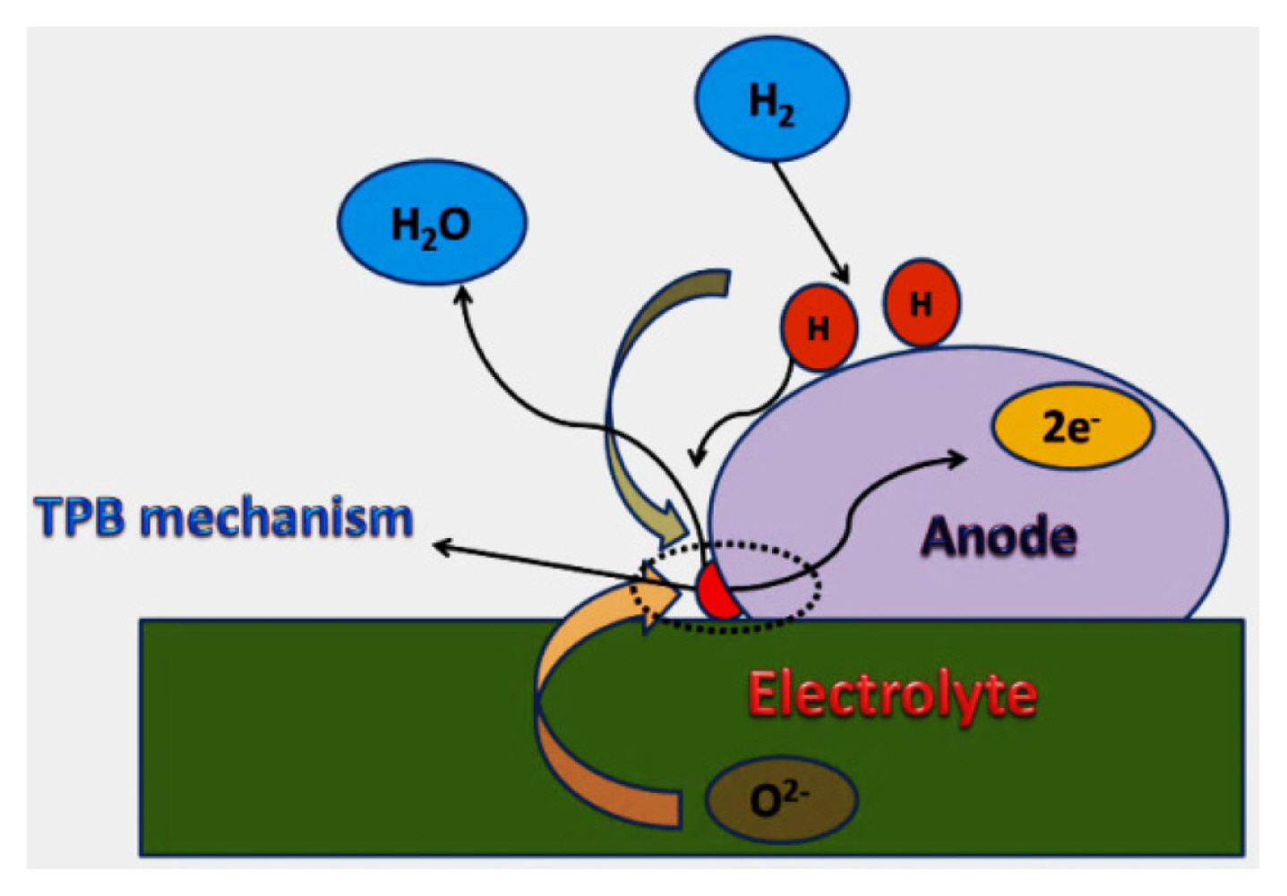
Schematic representation of TPB mechanism occurs in anode side of SOFC.
6. Efficient interconnecting materials for SOFC
Interconnecting materials electrically associate the anode of one cell to cathode of other in SOFC. It also plays a role of physical hinder in segregating two compartments and prevent mixing of gases [98]. The interconnecting material has to meet up some important common requirements for better performance which are as follows: a) it should possess excellent electrical conductivity, b) it should possess stability in both oxidizing and reducing environment during the service lifetime of SOFC, c) it should be impermeable for hydrogen and oxygen gas to avoid mixing during the operation of SOFC, d) the thermal expansion coefficient should be matched with other components of the SOFC and e)it should not react with the other components of the SOFC and f) it should be low cost and easily available [99].
Ceramics and metallic alloys are proposed as two main materials for interconnects in SOFC. The conventional material used for SOFC interconnect is lanthanum chromite (LaCrO3) for high temperature applications [100]. Since LaCrO3 is a p-type semiconductor, during the substitution of divalent ion on La site charge compensation exhibits due to valence change in Cr (Cr3+-Cr4+) [101]. Doped LaCrO3 shows better performance than the former. The main problem with these types of materials is their sinterability, because at high temperature there is a chance of volatilability of chromium. To avoid this, new strategies such as low temperature synthesis techniques and new fabrication techniques like freeze drying, microwave sintering, etc. were emerged [102]. Some of the doped LaCrO3 ceramic interconnects and their characteristics are presented in Table 5 [103]. Compared to ceramic oxide interconnects metal interconnects have the following benefits: a) High thermal conductivity, b) mechanical stability is higher, c) no gaseous permeation and d) electrical conductivity is higher [104]. In case of metallic interconnects, it is possible to lower the operating temperature of SOFC. Its availability, lower cost and ease fabrication makes their use more attractive in SOFC interconnects. Fe-Cr based alloys, Cr based alloys and Ni-Fe-Cr based alloys were so far employed for SOFC interconnecting materials [105]. Most of the metals are unstable in air, so oxidation resistance is a key issue for metallic interconnects. Although metals are excellent electrical conductors, the oxide scales formed during high-temperature exposure in air have much higher resistivity, which, as a result, increases the overall electrical resistance of the metal over time. Therefore, certain additives are used to reduce the electrical resistance of the oxide scale formed on the metallic interconnect material. However, an increase in ions and electrons transport rates will also lead to rapid oxide scale growth, which consequently degrades the oxidation resistance of the material. Thus, the composition of metal for interconnects needs optimization such that adequate electrical conductivity (i.e., 0.1 Scm−1 at operating temperature) and good oxidation resistance can be achieved [106]. Chromia forming alloys coated with oxides like, La2O3, Nd2O3 and Y2O3 by metal organic chemical vapour deposition (MOCVD) are effectively proposed as interconnecting material for SOFCs working at temperatures between 800–1000°C [107]. Stability and inert characteristics in the oxidizing atmosphere can make silver as a good candidate for cathode interconnect material in ITSOFCs [108]. However, we need to use suitable metallic components with excellent surface phenomena, structure and electrical stability and compatibility with other components for application in LTSOFCs [109]. The performance characteristics of SOFC interconnector materials are indicated in Table 5.

SOFC interconnector materials and their performance characteristics.
7. Fuels used in SOFC
SOFC has multiple fuel choices due to its high temperature of operation. The fuel choice highly depends on operating temperature of the cell. SOFC using hydrogen, methane and natural gases as a fuel has attained the attraction in upcoming commercial applications for power generations [112]. SOFCs require only a single partial oxidation reformer to pre-process their fuel, which can be gasoline, diesel, natural gas, etc. [113]. The nature of the emissions from the fuel cell will vary correspondingly with the fuel mix. Using hydrocarbons, for which a supply infrastructure is currently available, offers a variety of advantages over hydrogen since hydrocarbons are much easier to transport and to store because they are in a stable state which requires no processing before use. They are also more efficient at producing energy. Methane for example yields eight electrons per molecule whereas hydrogen only yields two electrons energy. This advantage could be magnified with the use of more complex hydrocarbons, such as pentane. Propane and butane are preferred for portable applications due to their higher density [114]. For portable fuel cell applications methanol and ethanol were used. Natural gas and hydrocarbons can be efficiently internally reformed in SOFCs operating above 600°C. For SOFC’s working below 500°C, oxygenates such as methanol and ethanol are considered as the most suitable fuels due to low temperature required for reforming these fuels. The efficiency was also differed for the usage of different fuels for the same compositions of SOFC component. Some of them are listed below in Table 6.

SOFC Fuel choices and their performance characteristics.
8. Fabrication SOFC components
Fabrication techniques used for making nanostructured ceramic components play important roles in the performance of SOFC. Now-a-days, to increase the performance of SOFC at low temperature, in addition to the research on finding high ionic conducting electrolytes, reducing the thickness of available electrolyte is also an hot topic of research. This enhances the reaction and transport kinetics at relatively low temperature [115]. Important fabrication techniques used to make different electrode and electrolyte components are listed in Tables 2, 3 and 4. Brief discussion about these techniques is mentioned below:
8.1. Tape casting
Tape casting is a technique widely used for the fabrication of thin films of porous and dense ceramics materials. Deposition of ceramic film is done by a temporary support consisting of mobile sheet. Doctor blade device is used to have desired thickness. Film thicknesses from 5 μm to a few millimeters can be obtained easily using tape casting. This method is even suitable for multilayer coatings. When nanostructured materials are prepared as thin tapes they tend to increase the electrode performance and minimize the resistance [116]. Za et al. have examined the microstructure of cathode graded with fine LSCF layer by tape casting having thickness of 40 μm to increase the active site of oxygen reduction in SOFC. The graded tapes have the coarse outer-layer with 1–3 mm grain size and fine inner-layer with 50–300 nm grain size, respectively. These cathodes dramatically increased the cathode performance of LSCF, since fine inner layer showed higher surface area and smaller grain size, which significantly increases the number of active sites for oxygen reduction compared to a single coarse layered LSCF commercial cathode [117]. A 10 cm × 10 cm and 0.17 mm thick supported Sc0.1Ce0·01Zr0·89O2+Δ (SSZ) electrolyte obtained by aqueous tape casting process resulted in high open-circuit voltage in SOFC device [118]. SOFC components can be made easily with this process with suitable composition of ingredients for effective application. A schematic of a double tape casting process used to prepare GDC -YSZ electrolyte tape is given in Fig. 8 [119].

8.2. Screen Printing
Screen-printing is widely used to fabricate SOFC components having thickness in the range of 10–100 μm. Fabrication of optimized screen-printing inks is highly significant for the production of high quality films with improved performance. In screen printing, the prepared suspension is placed on the screen and is forced by pressure for its passage [120]. Ling et al. have fabricated nanostructured SOFC components, viz., Sm0.5Sr0.5Cu0.2Fe0.8O3−δ cathode, SSFCu-SDC composite anode and SDC electrolyte using screen printing technique. The SOFC device with screen printed components resulted in excellent performance with 808 mWcm−2 [35].
8.3. Infiltration
It is a more effective and conventional method for low-temperature nano-fabrication of SOFC. Infiltration is performed by introducing the precursor metals of the cathode material in the form of a mixed metal salt solution into a fully sintered backbone of the O2− ion conducting phase. Upon heat treatment, the metal salts are decomposed and produce nanoparticles of the desired electrode material. Nano-fabrication by infiltration provides the advantages of low-temperature fabrication which avoids the unwanted interactions between the cathode and the electrolyte and also provides a nanostructured cathode which minimizes the effect of thermal expansion mismatch [121]. Babaei et al. have studied the electrochemical performance of LSM cathode with infiltration of nano-catalyst La2NiO4(size of 40 nm) (amixed ionic and electronic conductor) in it. It reduces the resistance from 26.2 to 2.5 Ωcm2 and the activation energy from 130 to 103kJ mol−1 at 650°C [122].
8.4. Atomic plasma spraying method
Plasma spraying is one of the emerging techniques to develop nanostructured functional layers for SOFC. It offers distinct advantages in terms of short fabrication time for the deposits, simple automation and up-scalability. It employs rapid deposition and is used for films having varying microstructure and compositions. In this technique, SOFC layers can be deposited without sintering on metallic substrates [123]. Hwang et al. have reported the preparation of nanostructured yttria stabilized zirconia-nickel (YSZ/ Ni) cermet anode by atmospheric plasma spraying (APS) technique. The performance of the SOFC is reported to be around 170 mWcm−2 at 700°C [124]. Stover et al. have prepared NiO-YSZ anode with APS and assembled SOFC with LSCF cathode and YSZ celectrolyte. The optimized cells showed at 0.7 V cell voltage a power density of 500 mWcm−2 @ 800°C [125].
8.5. Chemically assisted electro deposition (CAED)
It is a recent technique emerged for the low temperature (800–900°C) nano-fabrication of SOFC. It drastically increases the performance of the electrodes because of the high active surface area and high electro-catalytic activity. This technique can be used to fabricate the nanostructure components in a single step compared to other techniques. Rehman et al. have fabricated nanostructured LNO/GDC composite cathode by CAED technique which exhibited superior performance in terms of power density due to its high electro-catalytic activity for the ORR as compared to SOFCs consisting of LNO/GDC composite cathode fabricated by other methods. The overall performance was 973mWcm−2 at 750°C [121]. The anode-supported SOFCs with nanofibrous LCO cathodes prepared by CAED on zirconia and ceria scaffolds resulted in high and stable electrochemical performance of 0.95 and 1.27 W cm−2, respectively, at 800°C [126].
8.6. Electrohydrodynamic jet (E-jet) printing
It is an advanced printing technique using an electric field to create the flow of inks from a nozzle via electrohydrodynamics. This technique can deliver very small droplets or flows of inks for high resolution printing. Pham et al. [127] have described the fabrication of an anode functional layer for an electrolyte-supported SOFC using E-jet printing technique. An ink containing nickel oxide and 10% scandia-stabilized zirconia (10ScSZ) was used to print on an electrolyte plate. To vary the structure and morphology, they investigated different parameters. Multiple anode functional layers can be fabricated using this method.
Even though there are more techniques are available for fabrication, we have discussed only few techniques just to give the readers a brief idea about important SOFC fabrication techniques. Other techniques like sputtering, chemical vapor deposition (CVD), pulsed lased deposition (PVD), painting etc. can also be used for the fabrication of components in SOFC.
9. Future scope of SOFC research
Nanostructured ceramic materials have been studied by various researchers especially to operate the SOFCs at lower temperatures (500–800°C). By choosing right materials with suitable fabrication techniques, efficient components can be made for SOFC application especially for low temperature operation. Even though, the available materials show reasonable good performance, researchers may go for alternate synthesizing routes and fabrication procedures to improve the characteristics of SOFCs still further. To increase the TPB density, the study of novel materials having mixed ionic and electronic conductivity is still required. In case of anode, polarization resistance should be taken care and more research is needed to reduce it in case of low operating temperature. In total, suitable methodologies are required to operate LTSOFCs at reduced cost. Then only, the LTSOFCs can be commercialized to meet the immediate energy requirements of the globe.
10. Conclusions
This article reviewed the ceramic / nanostructured materials and components used in SOFC technology at different temperature of operations. Apart from the state-of-the cathode (La1−xSrxMnO3−δ), many novel materials such as, Sm0.5Sr0.5CoO3−δ, BaCo0.4Fe0.4Zr0.1Y0.1O3−δ, etc. have been developed with excellent characteristics for low temperature SOFC application. For anode, apart from Ni-YSZ, novel materials viz., La0.9−x CaxCe0.1CrO3−δ, Al0.10NixZn0.9−x/GDC, Ce0.9Gd0.1O2-Y2O3, etc. have been reported for low temperature application. Because of mismatching thermal expansion coefficient values with the adjacent components, state-of-the-art anode (Ni-YSZ) was replaced by variety of novel materials especially based on ceria based composites / perovskites, etc. For electrolyte, apart from ceria based materials, ceramic / nanocomposite materials such as, Er0.4Bi1.6O3, Dy0.08W0.04Bi0.88O1.56, BaZr0.1Ce0.7Y0.1O3−δ, BaCe0.7In0.3O3δ-Gd0.1Ce0.9O2−δ etc. have also been reported with excellent oxide ion conductivity values (with more than 0.1 Scm−1 at < 700°C). For interconnecting materials, metallic alloys were proposed because of their low cost and ease fabrication procedures. The TPB mechanisms occurred in anode and cathode surfaces will also play key roles in improving the performance of LTSOFC systems. At low temperature operation, variety of fuels can also be recommended. Careful attention is required to develop right SOFC materials and components which can exhibit better performance at low temperature (<600°C) operation. Also, the synthetic routes for the preparation of materials and the fabrication procedures will also impact the final performance of SOFC especially for low temperature (<600°C) operation. Nanostructured ceramic materials may be chosen carefully with improved characteristics for application in SOFC systems. New materials are still required especially to improve the activity and lifetime of LTSOFC in order to go for early commercialization.
Acknowledgment
The authors would like to thank Central Power Research Institute (Ministry of Power, Govt. of India) (Grant No.CPRI/ R&D/ TC/ GDEC/ 2019, dated 06-02-2019) for financial support. ASN acknowledges the management of Karunya Institute of Technology and Sciences for providing necessary facilities to initiate Fuel Cell research activity in the Department of Applied Chemistry.