UV-cured Polymer Solid Electrolyte Reinforced using a Ceramic-Polymer Composite Layer for Stable Solid-State Li Metal Batteries
Article information
Abstract
In recent years, solid-state Li metal batteries (SSLBs) have attracted significant attention as the next-generation batteries with high energy and power densities. However, uncontrolled dendrite growth and the resulting pulverization of Li during repeated plating/stripping processes must be addressed for practical applications. Herein, we report a plastic-crystal-based polymer/ceramic composite solid electrolyte (PCCE) to resolve these issues. To fabricate the one-side ceramic-incorporated PCCE (CI-PCCE) film, a mixed precursor solution comprising plastic-crystal-based polymer (succinonitrile, SN) with garnet-structured ceramic (Li7La3Zr2O12, LLZO) particles was infused into a thin cellulose membrane, which was used as a mechanical framework, and subsequently solidified by using UV-irradiation. The CI-PCCE exhibited good flexibility and a high room-temperature ionic conductivity of over 10−3 S cm−1. The Li symmetric cell assembled with CI-PCCE provided enhanced durability against Li dendrite penetration through the solid electrolyte (SE) layer than those with LLZO-free PCCEs and exhibited long-term cycling stability (over 200 h) for Li plating/stripping. The enhanced Li+ transference number and lower interfacial resistance of CI-PCCE indicate that the ceramic-polymer composite layer in contact with the Li anode enabled the uniform distribution of Li+ flux at the interface between the Li metal and CI-PCCE, thereby promoting uniform Li plating/stripping. Consequently, the Li//LiFePO4 (LFP) full cell constructed with CI-PCCE demonstrated superior rate capability (~120 mAh g−1 at 2 C) and stable cycle performance (80% after 100 cycles) than those with ceramic-free PCCE.
1. Introduction
Li-ion batteries (LIBs) are considered the most dominant power source for portable electronic devices and electric vehicles [1–5]. Despite considerable performance enhancements in terms of energy density, power, and cycle life, the use of flammable organic liquid electrolytes in LIBs has caused critical concerns regarding safety and reliability, which hinders the practical application of LIBs in large-scale energy storage systems [6–9]. Recently, solid-state batteries (SSBs) have been regarded as a fundamental technical solution to the safety problems of LIBs and have attracted increasing attention. Solid electrolytes (SEs), the main component of SSBs, can effectively suppress the formation and growth of Li dendrites, thus enabling the construction of high-energy-density batteries with Li metal, which have been highlighted as the ultimate anode for next-generation batteries owing to their unique properties such as high specific capacity (3,860 mAh g−1), low redox potential (−3.04 VSHE), and lightweight (0.59 cm−3) [8–20].
To achieve solid-state Li metal batteries (SSLBs) with high performance, SEs should meet various technical requirements for Li+ conduction, mechanical strength, flexibility, intimate contact with the electrode, ease of fabrication, and chemical/electrochemical/thermal stabilities to ensure target applications [21–26]. In general, SEs can be categorized into two major types (inorganic-based SEs and polymer-based SEs), and each SE has explicit advantages and disadvantages. Among inorganic SEs, oxide-based SEs with garnet-, perovskite-, and NASICON-type structures have high Li+ transference numbers, wide electrochemical windows, and good chemical/structural stabilities. However, the fabrication of thin SE films with high flexibility, Li+ conductivity, and good interfacial contact has been found to be challenging for oxide-based SEs. From a practical point of view, the use of polymer SEs consisting of a polymer matrix and Li salt seems to be more suitable for SSLBs owing to their unique features regarding their weight, deformability, flexibility, and processability [21–26].
Among the various polymer electrolytes, succinonitrile (SN)-based plastic-crystal polymer electrolytes (PCPEs), composed of a plastic crystal with a cross-linked polymer matrix, have been extensively explored as promising polymer SEs for SSLBs because SN-Li salt complex electrolytes can offer superionic Li+ conductivity of over 10−3 S cm−1 at room temperature [27–35]. The excellent Li+ conductivity of PCPEs may be ascribed to the decrease in the activation energy for Li+ conduction owing to trans-gauche isomerism [29–31]. However, despite these advantages, the insufficient mechanical properties of PCPEs should be addressed to effectively inhibit the formation of Li dendrites for practical applications in SSLBs. To strengthen the mechanical nature of flexible polymer SEs, various efforts have been devoted to developing novel designs of composite polymer electrolytes, such as garnet-structured ceramic/PCPE composite SEs, interfacial modifier-coated ceramic/PCPE biphasic sheets, and framework-reinforced PCPE membranes [36–39]. These hybridization strategies with mechanically reinforced matrices have been considered to enhance the mechanical strength of SEs, as well as the continuous/uniform Li+ conduction pathway at the interfacial contact with the Li metal, thus efficiently prohibiting the formation and growth of Li dendrites.
Herein, an asymmetric ceramic-integrated composite polymer electrolyte (CI-PCCE) is proposed to resolve the Li dendrite issues upon Li plating/stripping for the application of SSLBs. Cross-linkable poly(ethylene glycol) diacrylate (PEGDA), lithium bis(trifluoromethanesulfonyl)imide (LiTFSI), SN, and LLZO were used as the polymer-ceramic composite precursor sources, and a commercial cellulose-based membrane was employed as the mechanical support matrix. The one-sided LLZO-incorporated PCCE film was fabricated by infusing the precursor solution into the supporting matrix followed by the UV-induced cross-linking process. This asymmetrical configuration of the CI-PCCE film can guarantee close and conformal contact between the deformable polymer SE and the composite electrode on the side of the cathode and may allow uniform Li+ flux across the interface between the ceramic-incorporated composite SE and Li metal on the other side. Based on physicochemical and electrochemical analyses, the efficacy of the CI-PCCE film with an asymmetrical configuration was demonstrated to address the Li dendrite problems for the application of SSLBs.
2. Experimental
2.1. Materials
For this experiment, succinonitrile (SN, 99%, Sigma-Aldrich), lithium bis(trifluoromethanesulfonyl)imide (LiTFSI, 99.95%, Sigma-Aldrich), poly(ethylene glycol)diacrylate (PEGDA, Mn=700, Sigma-Aldrich), 2-hydroxy-2-methylpropiophenone (HMPP, 97%, Sigma-Aldrich), Li7La3Zr2O12 (LLZO, Toshima Mfg Co. Ltd, Japan) powder, fluoroethylene carbonate (FEC, 98%, Alfa Aesar), commercial cellulose separator (TF4035, NKK, Japan) was purchased and used.
2.2. Preparation of F-PCPE/CF-PCCE/CI-PCCE
At first, LiTFSI was completely dissolved in SN at 60°C to obtain 1.5 M SN-LiTFSI solution. Then, PEGDA (20 wt% to SN), FEC (5 wt% to SN), and HMPP (1 wt% to PEGDA) as a photoinitiator were added to prepare the well-mixed UV-curable PCPE precursor solution. LLZO powder with different mass ratios (SN/LLZO=90/10, 80/20, 70/30, 60/40 wt%) was also added into the above solution to prepare LLZO-mixed PCPE precursor solution. To fabricate the flexible and free-standing PCPE film (F-PCPE) without cellulose membrane, a PCPE precursor solution without LLZO was cast onto a glass plate and UV irradiation was exposed to both sides of the film for 20 s. To prepare the ceramic-free PCCE (CF-PCCE) film, the ceramic-free PCPE solution was poured into the commercial cellulose separator and then maintained for 3 h to be completely wetted in the pores of the separator. Then both sides of film were UV-cured for 30 s to obtain a thin CF-PCCE membrane with high flexibility. Ceramic-incorporated PCCE (CI-PCCE) was also prepared as a same manner by using a LLZO-mixed PCCE precursor solution.
2.3. Fabrication of PCPE-infused LFP electrode
The pristine LiFePO4 (LFP) composite electrode was prepared by casting a slurry consisting of LFP (active material), conducting agent, and PVDF (polyvinylidene fluoride, binder) (90:5:5 wt%) dissolved in N-Methyl-2-pyrrolidone (NMP) on an Al foil followed by vacuum drying at 120°C for 12 h and roll-pressing. To fabricate the PCPE-infused composite electrode, the PCPE precursor solution without LLZO was infused into the pristine LFP electrode and maintained in a vacuum for 3 h. Then, the infused-electrode was finally UV-irradiated for 30 s to completely solidify the PCPE in the composite electrode. In this work, the pristine electrodes with various mass loadings of ~5, ~9, ~14 and ~21 mg cm−2 were used. The densities of pristine- and PCPE-infiltrated electrodes were determined to be ca.1.8 and 2.2 g cm−3, respectively.
2.4. Material and electrochemical characterizations
The X-ray diffraction patterns were obtained with high-resolution powder X-ray diffractometer (XRD, SmartLab, RIGAKU) in the scan range region of 10–80°. The surface and cross-sectional morphological information for the SEs and composite electrodes were characterized by using field emission scanning electron microscopy (FE-SEM, Regulus 8220, HITACHI) combined with energy dispersive spectroscopy (EDS). FTIR spectroscopy (Nicolet Is50, Thermo Fisher Scientific Instrument) was carried out under the range of 400–4000 cm−1. Thermal gravimetric analysis (TGA, TG209 F1 Libra, Nechwi) was performed under the heating rate of 10°C min−1 in Ar atmosphere (30–500°C). The ionic conductivities of the SEs were determined using a symmetric cell with the configuration of SS | SEs | SS (SS: stainless steel). AC Impedance analysis was performed using an impedance analyzer (Bio-Logic SP-240) in the frequency range of 1 Hz–5MHz (Vrms=5.0 mV) from 25°C to 80°C. The oxidation stability of SEs was measured in the coin-type cell with the configuration of Li|SEs|SS by using linear sweep voltammetry (LSV) with a scan rate of 5 mV s−1. Galvanostatic electrochemical impedance spectroscopy (GEIS) measurements were performed on the Li symmetric cell (Li | SEs | Li) by applying a constant current density of 10 mA cm−2 with a current-perturbation of 5 mA cm−2. The Li+ transference number was measured on the Li symmetric cell by using analyses of AC-impedance spectra and DC polarization profiles with applying a constant voltage of 0.01 V. The durability and stability of the SEs with Li metal were investigated by the Li plating short circuit and the Li plating/stripping cycling test with a current density of 0.5 mA cm−2. For the electrochemical performances of full cells (Li | SEs | LFP), the galvanostatic charge-discharge tests were carried out at various current ranges of 0.2–3.0 C (1 C=170 mA g−1) at 45°C.
3. Results and Discussion
Fig. 1 illustrates the schematic synthesis procedure for the CI-PCCE membrane. To prepare CI-PCCE, UV-curable mixed precursors (SN, LiTFSI, PEGDA, and LLZO particles) were coated on one side of the cellulose film as a mechanical matrix, followed by UV-induced solidification. Here, SN, LiTFSI, PEGDA and LLZO may work as the plasticizer, Li salt, cross-linkable polymer and mechanical/interfacial modifier, respectively. The polymer precursor solution can be infused into the cellulose membrane; however, ceramic powders with a particle size of 0.5–2 μm (Fig. S1) cannot penetrate the interconnected pores of the membrane (Fig. S2). Thus, the one-sided LLZO-incorporated PCCE can be fabricated using a simple coating and UV-curing method. For comparison, free-standing PCPE without a supporting matrix (F-PCPE) and ceramic-free PCCE (CF-PCCE) films were prepared. Hereafter, the CI-PCCE samples fabricated using different amounts of LLZO (10, 20, 30, and 40 wt%) are referred to as C10-PCCE, C20-PCCE, C30-PCCE, and C40-PCCE, respectively.

Schematic diagrams for the synthesis procedure of the CI-PCCE.
First, the surface and cross-sectional morphologies of the various PCPE films were characterized using SEM and EDS. As seen in Fig. 2(a), the flexible and free-standing F-PCPE film with a thickness of ca. 200 μm shows a wrinkled surface morphology, whereas the cellulose membrane exhibits a highly porous structure formed by cross-stacked cellulose nanofibers (Fig. S2). Following the infusion of the ceramic-free PCPE precursor solution, it was observed that large pores formed by the cross-stacked nanofibers were completely filled by UV-cured PCPE, reflecting the formation of percolative Li+-conductive networks (Fig. 2(b)). The thickness of the prepared asymmetric CF-PCCE film was determined to be ~25 μm. In contrast, following the infusion of the LLZO-mixed PCPE precursor, the surface and cross-sectional SEM images (Fig. 2(c)) of CI-PCCE revealed that the PCCE-LLZO composite layer with a thickness of ~8 μm was only formed on top of the PCPE-infused cellulose matrix. EDS mapping results (from La and S elements in Fig. 2(d)) also indicated that LLZO particles were uniformly incorporated into the PCPE matrix of the composite layer, and the infiltrated PCPE was well distributed throughout the cellulose membrane.
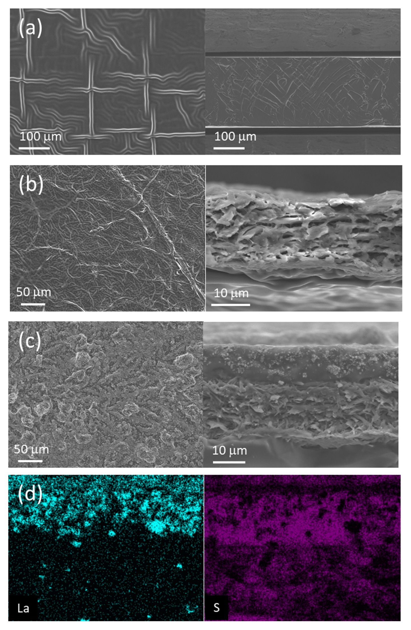
Surface and cross-sectional SEM images of (a) F-PCPE, (b) CF-PCCE, and (c) CI-PCCE. (d) Corresponding EDS mapping results of La and S elements for the cross-sectional image of CI-PCCE.
The microstructural characteristics of the prepared PCPE films were determined using XRD and FTIR analyses. Fig. 3(a) presents the XRD patterns of the F-PCPE, CF-PCCE, CI-PCCE, and LLZO. While the XRD profiles of F-PCPE and CF-PCCE show broad and amorphous-like diffraction peaks in the range of 15–30° owing to the complex formation of the plastic-crystal polymer and Li salt, CI-PCCE exhibits additional crystalline peaks corresponding to the garnet-type LLZO phase. This indicated that the crystallinity of the LLZO particles was well preserved in the polymer matrix, and LLZO had good chemical compatibility upon hybridization with the plastic-crystal-based polymer. The crosslinking and polymerization of the PEGDA monomer by the UV-curing process were examined by FTIR analysis as presented in Fig. 3(b). The FTIR spectra of the polymer precursor clearly exhibited characteristic absorption peaks at 1617 cm−2 and 1717 cm−2 caused by the stretching vibrations of C=C and C=O bonds, respectively. After UV irradiation, the C=C vibration peak disappeared, and the C=O peak shifted from 1717 cm−2 to 1730 cm−1, implying the breaking of the C=C bond and complete polymerization of the PEGDA molecule [38,39]. Furthermore, the thermal stabilities of the PCPE films were characterized using thermo-gravimetric analysis (TGA), as shown in Fig. 3(c). It was observed that all the PCPE films began to abruptly lose weight from ca. 150°C, which can be attributed to the thermal decomposition of SN (Fig. 3(d)). At 500°C, the remaining weights of F-PCPE, CF-PCCE, and CI-PCCE were ca. 6, 8, and 23%, respectively, implying the enhanced thermal stability of CI-PCCE owing to the incorporation of ceramic particles.

(a) XRD patterns and (b) FTIR spectra for the F-PCPE, CF-PCCE and CI-PCCE. TGA results (c) for F-PCPE, CF-PCCE, and CI-PCCE, and (d) for various precursor materials.
To examine the Li+-conducting properties of the PCCE films, AC impedance measurements at temperature ranges of 25–80°C were conducted on the symmetric cells (SS | PCCE films | SS, SS: stainless steel) for the PCCE films with various LLZO contents, as shown in Fig. 4(a). Fig. 4(b) shows the dependence of the Li+ conductivity on the LLZO content measured at 25°C. Compared to F-PCPE (1.7 mS cm−1), the PCCE membranes exhibit lower conductivity values, which is mainly ascribed to the hindered Li+ transport caused by the implementation of a porous framework with higher tortuosity. With the exception of C10-PCCE (~1.1 mS cm−1), it was also observed that the other CI-PCCEs have a lower ionic conductivity than CF-PCCE (~1.0 mS cm−1). It seems that the excessive incorporation of the ceramic particles may induce poor interfacial contact between LLZO and the PCPE matrix, thus impeding Li+ conduction through the PCCE membrane. Fig. 4(c) illustrates the Arrhenius plots of the ionic conductivity of the PCCE films with various LLZO contents. It was observed that the the dependence of conductivity with 1/T is slightly deviated from the linearity, which implies that the ion motions in PCCE are strongly related to the long-range motions of the polymer matrix based on the Vogel- Fulcher-Tamman (VFT) model [40,41]. In addition, the electrochemical anodic stability of the PCCEs was examined using linear sweep voltammetry (LSV). Fig. 4(d) revealed that the PCCE films with and without LLZO would be electrochemically stable up to ~4.15 V vs. Li/Li+, which may guarantee the stable operation of LFPbased cathode.
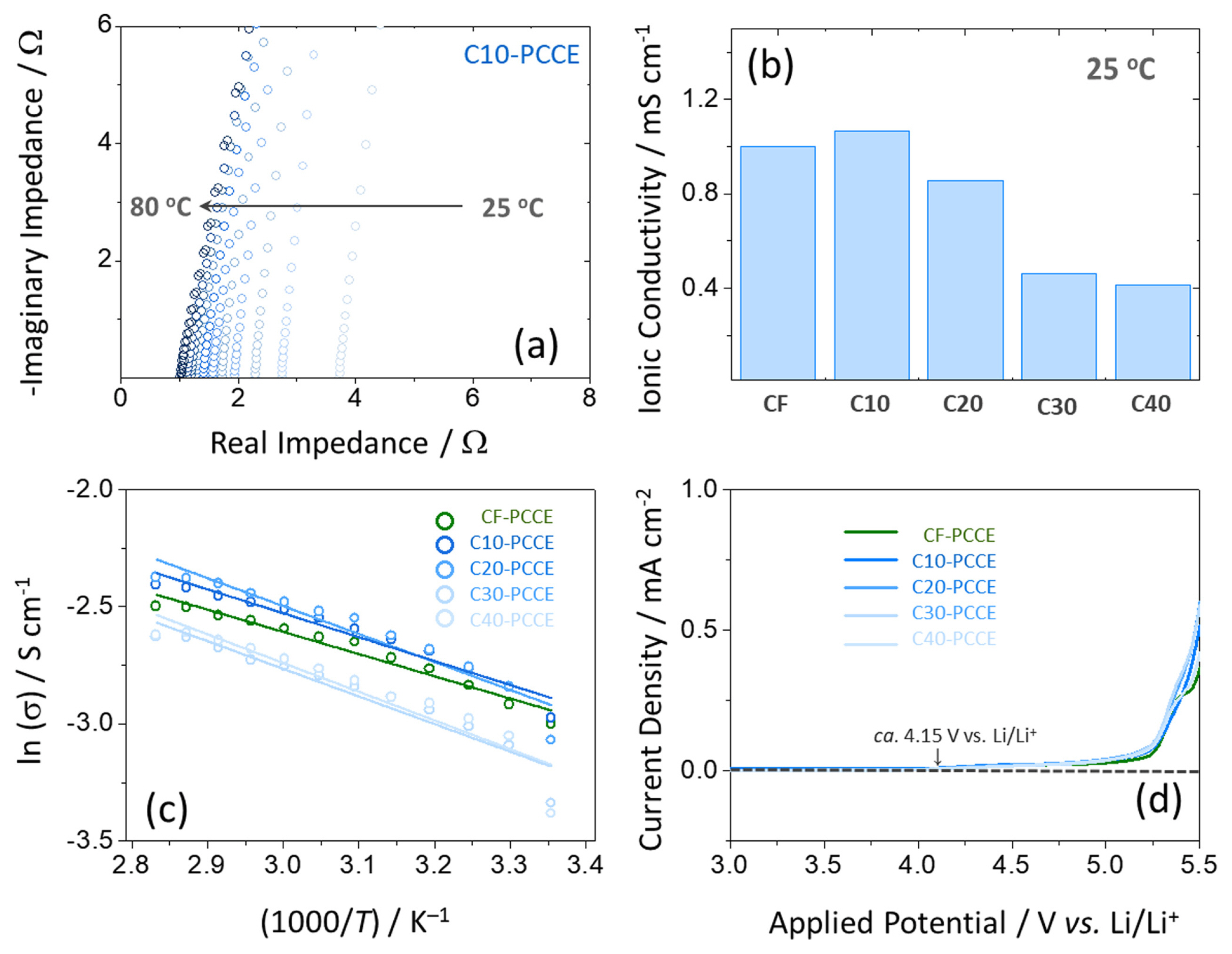
(a) AC-impedance spectra of C10-PCCE measured at temperature ranges of 25–80°C. (b) Ionic conductivities evaluated at 25°C, (c) temperature dependence of ionic conductivity, and (d) linear sweep voltammograms for various PCCE films.
To explore the durability and stability of the PCPE films against Li dendrite formation, Li plating/stripping tests were conducted on a symmetric cell (Li | PCPEs | Li). Fig. 5(a) presents the charging curves of the symmetric cells assembled with various PCPE films at a current density of 0.5 mA cm−2. It was found that all potential profiles exhibit a sudden potential drop upon charging, indicating the lithium dendrite penetration through the PCPE films and internal shorting between the two Li metals [42]. The charge capacity measured at the short-cirucit point increases in the order of F-PCPE (0.6 mAh cm−2) < CF-PCCE (2.9 mAh cm−2) < C10-PCCE (4.4 mAh cm−2) < C20-PCCE (6.6 mAh cm−2) < C30-PCCE (8.3 mAh cm−2) < C40-PCCE (9.8 mAh cm−2), clearly reflecting the linear dependancy of the mechanical strength (LLZO contents) of PCCEs with the durability against Li dendrite. Fig. 5(b) presents the cycling performance of the symmetric cells measured with an areal capacity of 0.1 mAh cm−2 at an applied current density of 0.5 mA cm−2. The symmetric cell with C10-PCCE exhibited a stable Li plating/stripping behavior for more than 200 h, while the CF-PCCE suffered from short-circuiting after ~120 h. These results clearly demonstrate that mechanically reinforced PCCEs are highly effective in regulating lithium plating/stripping and suppressing lithium dendrite growth. Moreover, the Li+ transference numbers for CF-PCCE and CI-PCCE were determined to be 0.49 and 0.59, respectively, based on the Bruce-Vincent method [43], as shown in Figs. 5(c) and S3. The enhanced Li+ transference number for the CI-PCCE may be attributed to the immobilization of anions (TFSI−) at the surface of the LLZO particles [44], thus enabling the homogenization of Li plating/stripping by uniformly distributing the Li+ flux across the interface between the Li anode and PCCE. Furthermore, the lower interfacial resistance for CI-PCCE (Fig. 5(d)), which is evaluated from the acimpedance spectra using the GEIS method [45], corroborates the facilitated Li+ transport across the Li metal interface during Li plating/stripping conditions.

(a) Galvanostatic charging profiles of various PCPE films, and (b) cycling performance of CF- and CI-PCCEs with an areal capacity of 0.1 mAh cm−2 measured on the Li-symmetric cells. (c) DC polarization curve and AC-impedance spectra for CI-PCCE. (d) Galvanostatic electrochemical impedance spectra for CF- and CI-PCCEs.
Prior to demonstrating the performance of the full cell with the CI-PCCE films, morphological information on the composite cathodes was obtained by analyzing the SEM and EDS results to assess the complete penetration and uniform distribution of PCPE in the composite electrode. Figs. 6(a) and (b) illustrate the cross-sectional SEM results for the pristine and infused LFP electrodes, respectively. The pristine LFP electrode had a porous structure formed by the dense packing of nano-sized LFP particles and other constituents, whereas the interparticle pores for the PCPE-infiltrated electrodes were entirely occupied by the infused PCPE (the insets of Figs. 6 (a) and (b)). In particular, the EDS mapping results of the infiltrated electrode (Fig. 6(c)) revealed the complete penetration of PCPE, even at the bottom of the electrode with a thickness of ~50 μm, implying the good penetration ability and wettability of PCPE. Moreover, based on the almost identical XRD profiles (Fig. 6(d)) of the pristine and infiltrated electrodes, except for the appearance of a broad peak owing to the amorphous feature of the infused PCPE, it was confirmed that the infused PCPE could penetrate the composite electrodes without producing any side reactions with the other ingredients of the electrode.

Cross-sectional SEM micrographs for (a) pristine and (b) PCPE-infused composite electrodes. (c) EDS mapping results of Fe, P and S elements for PCPE-infused electrode. (d) XRD patterns of pristine and PCPE-infused LFP electrodes.
To demonstrate the efficacy of the ceramic-incorporated PCCE films for practical applications, SSLBs with the configuration of [Li metal (anode) | PCPE (SE) | PCPE-infiltrated LFP (cathode)] were fabricated, and their electrochemical performances were evaluated. Fig. 7(a) displays the galvanostatic charge–discharge profiles of SSLBs assembled with F-PCPE, CF-PCCE, and C10-PCCE obtained at the initial and 10th cycles with an applied current density of 34 mA g−1 (0.2 C). The SSLBs with CF-PCCE and C10-PCCE clearly showed a higher initial discharge capacity of ca. 155 mAh g−1 and smaller charge-discharge overpotentials (~80 mV) than those of F-PCPE (147 mAh g−1 and ~ 200 mV), which is mainly ascribed to the lower conductance of bulk F-PCPE (thickness: ~200 μm). In particular, it was found that F-PCPE exhibits potential fluctuation behavior upon the 10th charging cycle, and the cell cannot charge to the upper cut-off potential, while the other cells operate well during the charge-discharge process. This strongly indicates that F-PCPE without a mechanical matrix is considerably vulnerable to Li dendrite growth and internal shorting, demonstrating the efficacy of the mechanical framework, which is corroborated by the symmetric cell results (Fig. 5(a)).
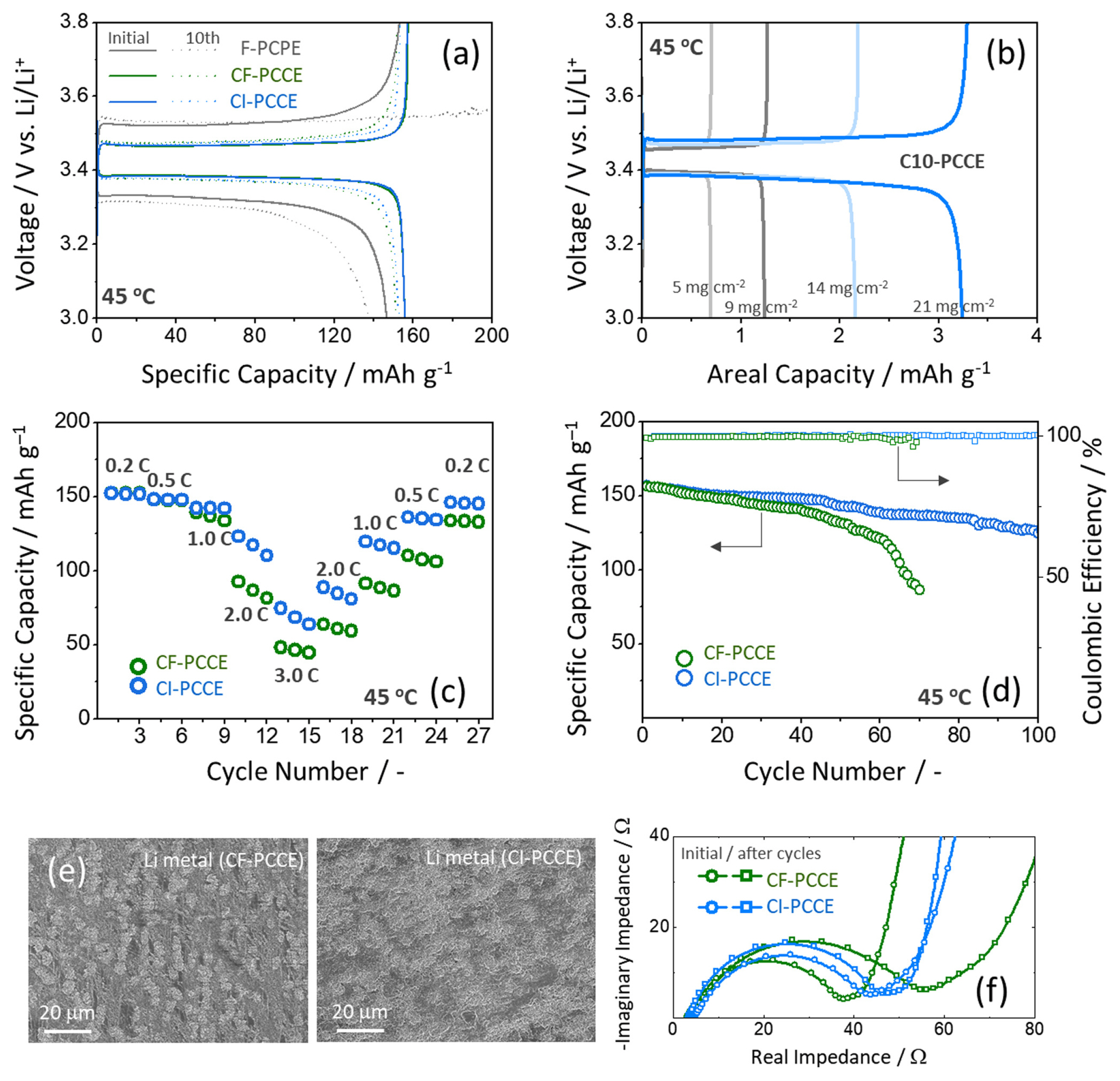
Galvanostatic charge-discharge profiles of full cells with various PCPE films at the initial and 10th cycles. (b) Charge-discharge curves of C10-PCCE with various mass loadings of LFP. Rate capability and cycle performance of the full cells with CF- and CI-PCCEs. (e) SEM micrographs of Li metal disassembled from the cycled full cells and AC-impedance spectra obtained from the full cells at initial cycle and after cycling.
Fig. 7(b) depicts the charge-discharge profiles of C10-PCCE with different electrode loadings meausred at 45°C. The linear relationship of the mass loading with the areal capacity for the SSLB and the high value (~92%) of cathode utilization even at high LFP loading of 21 mg cm−2 (~3.3 mAh cm−2) strongly represents the homogeneous distribution of PCPE in the composite cathodes and the high utilization of Li anode, respectively. The rate capabilities and cycle stabilities of CF-PCCE and C10-PCCE were also examined, as illustrated in Figs. 7(c) and (d). The cell with C10-PCCE delivered higher capacities than CF-PCCE over the entire current range of 34–510 mA g−1, and the discharge capacity of C10-PCCE, even at a high current density of 340 mA g−1 (2 C), was measured to be as high as ~120 mAh g−1. Moreover, SSLBS with C10-PCCE showed enhanced cycle stability (80% retention after 100 cycles), as shown in Fig. 7(d). These results suggest that the LLZO-PCPE composite layer in contact with the Li anode may be capable of efficiently regulating Li plating/stripping by uniformly homogenizing the Li+ flux across the interface between the Li anode and PCCE, thus enhancing the rate capability and cyclability of SSLBS. Compared to CF-PCCE, the uniform surface morphology of Li metal (Fig. 7(e)) and reduced cell resistance (Fig. 7(f)) of CI-PCCE obtained after cycling also demonstrated the efficacy of ceramic-incorporated PCCE for promoting the uniform Li plating/stripping of SSLBs.
4. Conclusions
In this study, we proposed a one-sided LLZO-incorporated polymer composite SE film formed via a facile UV polymerization process to ensure uniform Li plating/stripping for SSLBs. It was confirmed that CI-PCCE exhibited good flexibility and superionic Li+ conductivity at 25°C. Physicochemical and electrochemical analyses on the Li symmetric cell revealed that CI-PCCE has enhanced durability and stability against Li dendrite formation upon Li plating/stripping. The enhanced rate capability and stable cyclability of SSLBs with CI-PCCEs were also demonstrated. Based on the aforementioned results, it was suggested that the use of cellulose film as a supporting matrix may effectively reinforce the mechanical strength of the flexible composite SEs, and the ceramic-polymer composite layer formed on one side of the PCPE membrane can regulate the Li+ flux at the interface between Li and PCPE, thus inducing uniform Li plating/stripping. This plastic-crystal-based polymer SE, synergistically reinforced by incorporating ceramic and a supporting matrix, provides an alternative design strategy for developing high-energy-density SSLBs.
Acknowledgements
This research was supported by the Korea Institute of Energy Research (KIER, Project No. C2-2465) and Chungnam National University.
"Updated on 3 August 2023"
Notes
Declaration of Competing Interest
The authors declare that they have no known competing financial interests or personal relationships that could have appeared to influence the work reported in this paper.
Supplementary Information
Supporting Information is available at https://doi.org/10.33961/jecst.2022.00829