1. Introduction
The fourth industrial revolution has led to the emergence of hyper connectivity, superintelligence, automation, and mobility. Consequently, light-weight flexible batteries are gaining popularity for operating portable, wearable electronic devices. The development of flexible substrates and electrode materials is the most important step in the realization of a flexible energy-storage device [
1]. Metals that have been conventionally used for the substrate are susceptible to mechanical deformations such as bending, twisting, and stretching, which limits their use in flexible energy-storage devices. To address this issue, studies have been conducted on polymer [
2], paper [
3], or textile [
4] coated with a conductive material for use as a substrate.
In particular, paper is fairly inexpensive, environment friendly, light weight, and flexible, thereby making it suitable for use in flexible electrodes [
5]. Because it has a wide surface area, excellent battery characteristics can be expected by evenly coating its surface with a conductive material; the use of silver nanowire films [
6], conductive polymers [
7], metals, and carbon-based materials (e.g., carbon nanotubes [
8], graphene [
9], etc.) as the conductive coating has been investigated. Layer-by-layer (LbL) assembly [
10], dip coating [
11], dry coating [
12], electro- and electroless plating [
13,
14] are among the known coating methods. Through electroless plating, microfiber strands can be coated with a uniform thickness and at a low cost; various metals such as nickel, copper, gold, platinum, and cobalt can also be used as the conductive coating via electroless plating [
15].
Nickel phosphide has a wide variety of applications for functional electrochemical devices [
16ŌĆō
18]. In particular, much work has been recently made on its use for the anode in rechargeable lithium (Li) battery owing to its high theoretical specific capacity [
19,
20]. As far as we know, however, there was no report about metal phosphide coating on flexible substrate like paper, fiber, and polymer for the use of Li battery anode. Only a few works dealt with the electrochemical or electroless coating of metal phosphide anode on nearly inflexible foam frameworks [
21,
22].
In this study, a metal alloy was coated on the surface of cellulose paper (CP) to test its feasibility as the anode for Li batteries. Specifically, Hanji, Korean traditional paper, features excellent durability and mechanical strength, and the fiber bonding of Hanji is stronger than that of western paper [
23]; via electroless plating, its surface was coated with inexpensive nickel phosphide (Ni-P) with low surface resistance (below 0.5╬®Ō¢Ī
ŌłÆ1 [
24,
25]). Unlike conventional methods that utilize two separate materials for the flexible substrate and electrodes, CP can act as a flexible skeleton to maintain the mechanical structure, and the Ni-P film coated via electroless plating can play the roles of both the anode substrate and the active material (electrode material) in Li batteries.
First, electroless-plating conditions were varied to form films with different Ni-to-phosphorus (P) ratios on the surface of CP. The crystal structure and morphology (uniformity) of the formed films were analyzed, and the maintenance of structural integrity during the bending process was checked. To test the applicability of the CP/Ni-P film samples as Li battery anode, the charge/discharge capacity, lifespan, and resistance properties of the anode were analyzed. Moreover, the charge/discharge tendencies of the electrode before and after the mechanical bending were compared to identify the stress-induced changes in the electrochemical properties.
2. Experimental
2.1 Preparation of Ni-P electroless coating on CP
Hanji (100 ╬╝m in thickness, 20 ╬╝m in fiber diameter) was used for a flexible substrate. Electroless coating of Ni-P film on CP basically consists of pretreatments (i.e., sensitizing and activation) and main process (i.e., electroless deposition). Sensitizing process was done for 20 min. in an aqueous solution of 0.026 M tin chloride (Alfa Aesar, 98%), while activation process was carried out for 30 min. in a mixed aqueous solution of 1.7 mM palladium chloride (Aldrich, 99%) and 0.32 M boric acid (Junsei, 99.5%). The pH was set to 1 and 2 with hydrochloric acid (Junsei, 35%) in sensitizing and activation process, respectively.
Main deposition process was performed at 45┬░C. The deposition bath includes 0.097 M nickel sulfate (Junsei, 98.0%), 0.027 M trisodium citrate dehydrate (Junsei, 99%), 0.34 M ammonium chloride (Junsei, 98.5%), and 0.04 ~ 0.5 M sodium hypophosphite (Sigma-aldrich, 99%). The pH was controlled from 6 to 11 by sodium hydroxide (Junsei, 97.0%). Three compositions of deposition bath for electroless coating were given in
Table 1. The solution was stirred with a magnetic stirrer during all the processes. The prepared samples were washed in distilled water and air-dried. Some samples were treated with dilute hydrochloric acid to remove the native oxide layer on the films.
The surface and cross-sectional morphology, composition, and crystal structure of the films were analyzed using field-emission scanning electron microscope (FE-SEM, MIRA3, TESCAN, Czech Republic), energy dispersive X-ray spectrometer (EDS, 51-XMX1004, Oxford instruments, UK), X-ray diffractometer (XRD, Ultima-IV Rigaku, Japan), respectively.
2.2 Electrochemical Tests
For the tests of CP/Ni-P samples as the anode in Li batteries, three-electrode beaker cell was constructed in a glove box (Mbraun-Unilab, Germany) with high purity Ar gas (O2, H2O < 1 ppm). Li foil was used as the counter and reference electrode. The electrolyte was a 1 M solution of lithium hexafluorophosphate in a 3:7 volume mixture of ethylene carbonate and ethyl methyl carbonate.
In order to explore the effect of P content in Ni-P film on the specific capacity and cycling stability, the charge/discharge experiments were performed for three samples with different P contents. The cells were galvanostatically charged at a rate of 1 mAcmŌłÆ2 to 0.01, 0.1, or 0.3 V vs. Li/Li+, followed by a constant potential charging until the current has decreased to 0.2 mAcmŌłÆ2. They were subsequently discharged at a rate of 1 mA/cm2 to 3 V vs. Li/Li+. The above charge/discharge cycle was repeated 20 times. To estimate the interfacial resistance during charge/discharge cycle, electrochemical impedance spectroscopy (EIS) measurements were conducted over the frequency range of 10 kHz to 0.1 mHz at a potential fluctuation of 5 mV(rms). Some CP/Ni-P film samples were bent by wrapping them around a cylinder having a diameter of 3 mm, and their charge/discharge characteristics were analyzed. A VMP3 system (BioLogic Co., Claix, France) was used for all the electrochemical measurements.
3. Results and Discussion
To obtain Ni-P films with different P contents via electroless plating, the concentration of sodium hypophosphite (used as the reducing agent) and the pH (i.e., the concentration of sodium hydroxide) were adjusted (
Table 1). Because the reducing agent acts as the P source, increasing its concentration is expected to increase the P content, and this tendency has already been reported in a previous study [
26]. Further, considering the electroless-plating reaction mechanism presented below [
27], it is evident that the pH also influences the P content.
Specifically, an increase in the pH (i.e., an increase in the hydroxide ions in the solution) facilitates reaction (
1) and inhibits reaction (
2), thereby yielding a relatively low P content in the layer plated via electroless plating. Consequently, the P content in the layer tends to be proportional to the concentration of the reducing agent and inversely proportional to the pH. Therefore, increasing the concentration of the reducing agent and lowering the pH is ideal for obtaining a high P content, whereas the opposite is ideal for obtaining a low P content. The conditions presented in
Table 1 have been derived as a result of repeated experiments on this basis.
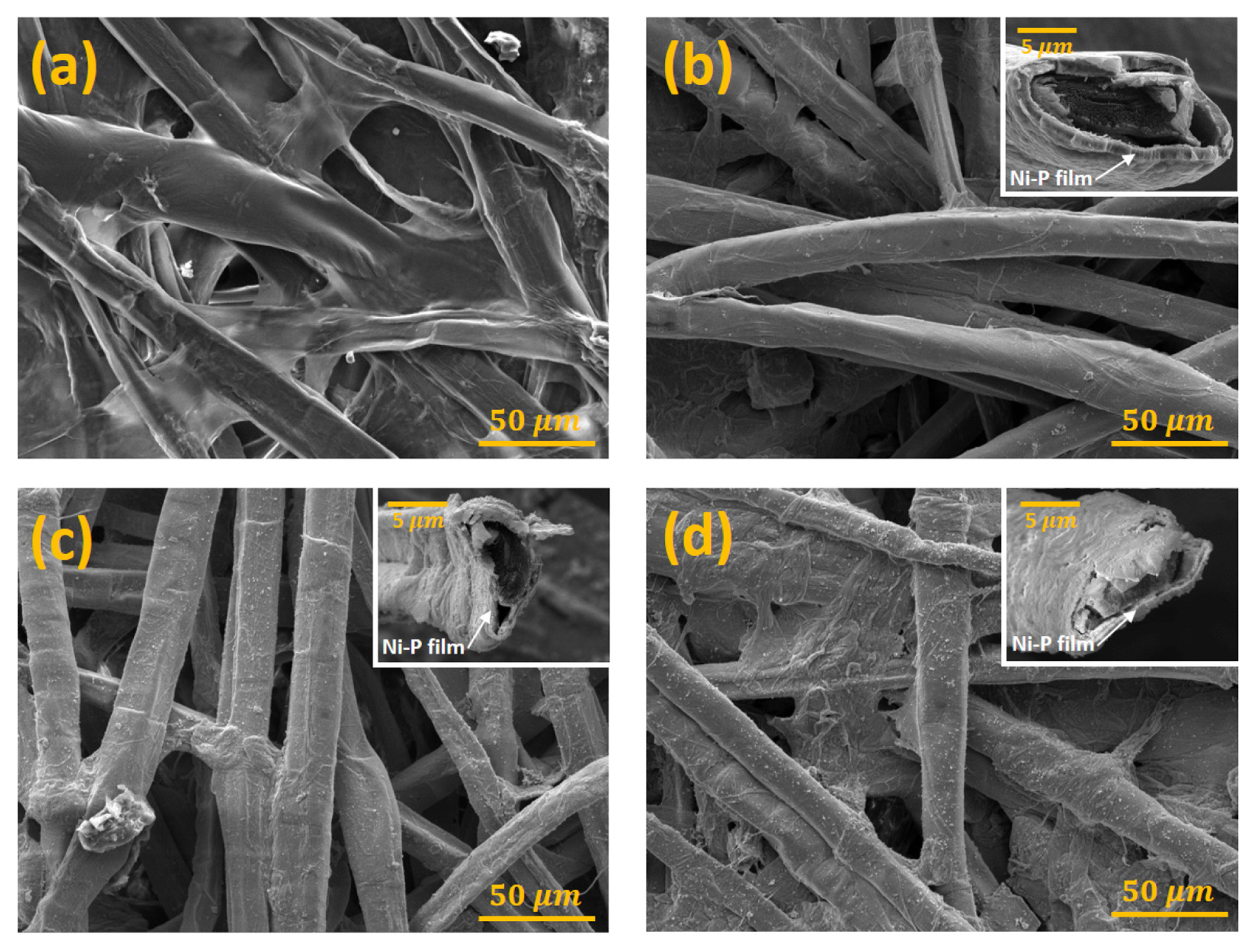
Fig. 1 represents the electron-microscopy images of the CP before electroless plating and the CP/Ni-P film samples fabricated under three different electroless- plating conditions presented in
Table 1. Before electroless plating, the CP had crosslinked microfiber strands with a diameter of approximately 20 ╬╝m (
Fig. 1(a)), and as a result, it had a very large surface area, and many pores were present inside it. Therefore, when a thin layer of the substrate/active material is uniformly coated on the fiber strands that comprise the CP, high capacity and low reaction resistance per physical area can be expected. Moreover, electrolyte impregnation becomes easier owing to the presence of numerous pores between the fiber strands.
Figs. 1(b), (c), and (d) represent the electron-microscopy images obtained after Ni-P film is coated on the surface of CP via electroless plating under conditions 1, 2, and 3, respectively. In all the three cases, Ni-P was plated uniformly on the microfiber strands. The inset image suggests that the thickness of the Ni-P layer was approximately 1 ╬╝m, highlighting the high-density plating.
Fig. 2 presents the results of the component analysis performed via EDS. Carbon and oxygen, which are the main components of cellulose, were mostly detected in the CP (
Fig. 2(a)), whereas the P content in the layers coated via electroless plating under conditions 1, 2, and 3 was ~3 at% (hereafter referred to as NiP3), ~6 at% (hereafter referred to as NiP6), and ~10 at% (hereafter referred to as NiP10), respectively (
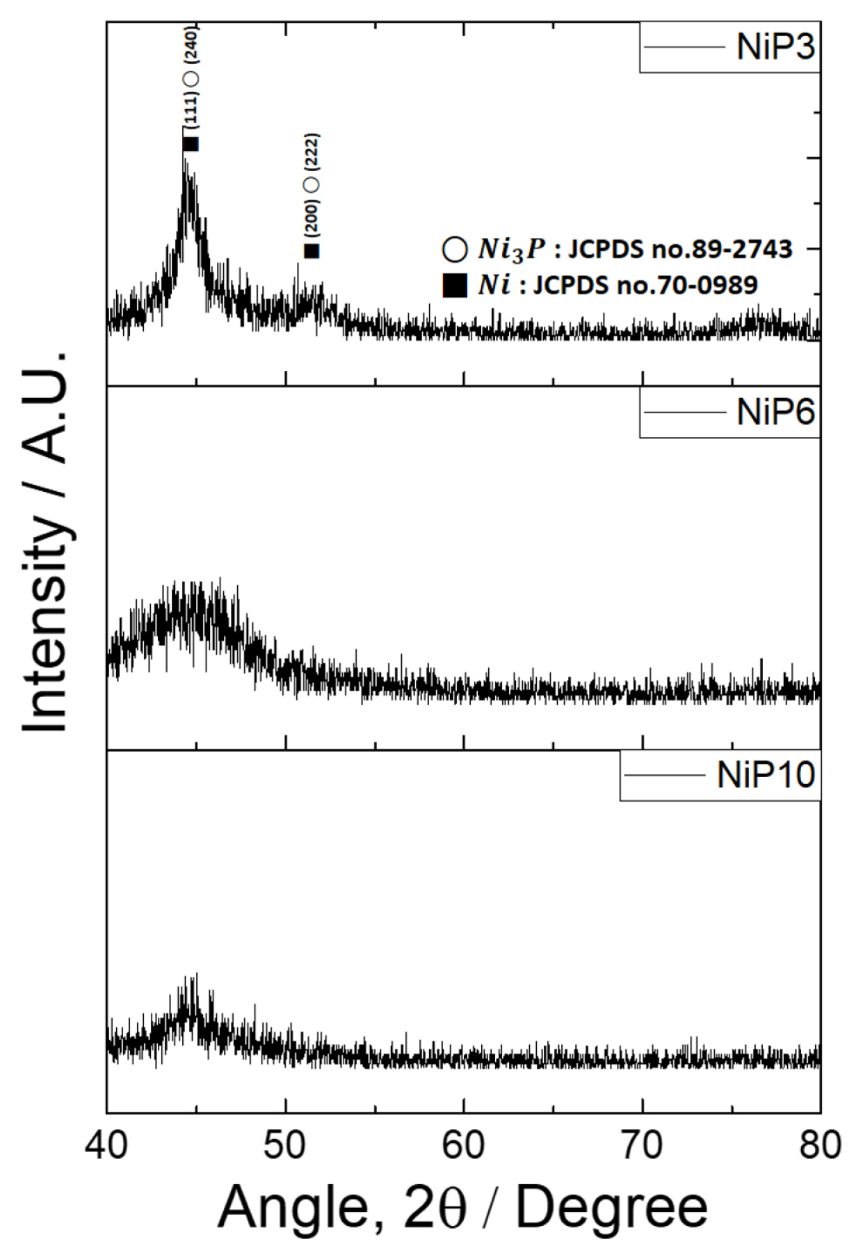
Figs. 2(b), (c) and (d)). In the analysis of the crystal structure of the plated layer (
Fig. 3), all three samples contained severe noise with diffraction signals. Although it appeared that the sample NiP3 has a partial crystallinity of Ni and/or Ni-P alloy, the corresponding signals were very weak and broad, and those from Ni and Ni-P alloy were hardly differentiable. Such signals obtained from NiP6 and NiP10 were observed far less clearly. These results reveal the short-range order in the structures of Ni and Ni-P alloy. It has been reported that the crystal structure of Ni-P coated via electroless plating is associated with the P content. When the P content is low (2 wt%), it has crystalline properties, but as the P content increases, it becomes more amorphous; when the P content exceeds 10 wt.%, it becomes completely amorphous [
28]. In this study, distinct X-ray diffraction signals were hardly observed even when the P content was relatively low; this can be attributed to the significantly low amount of crystalline materials.
For measuring the adhesive strength of the plated layers, scratch [
29] and splat adhesion tests [
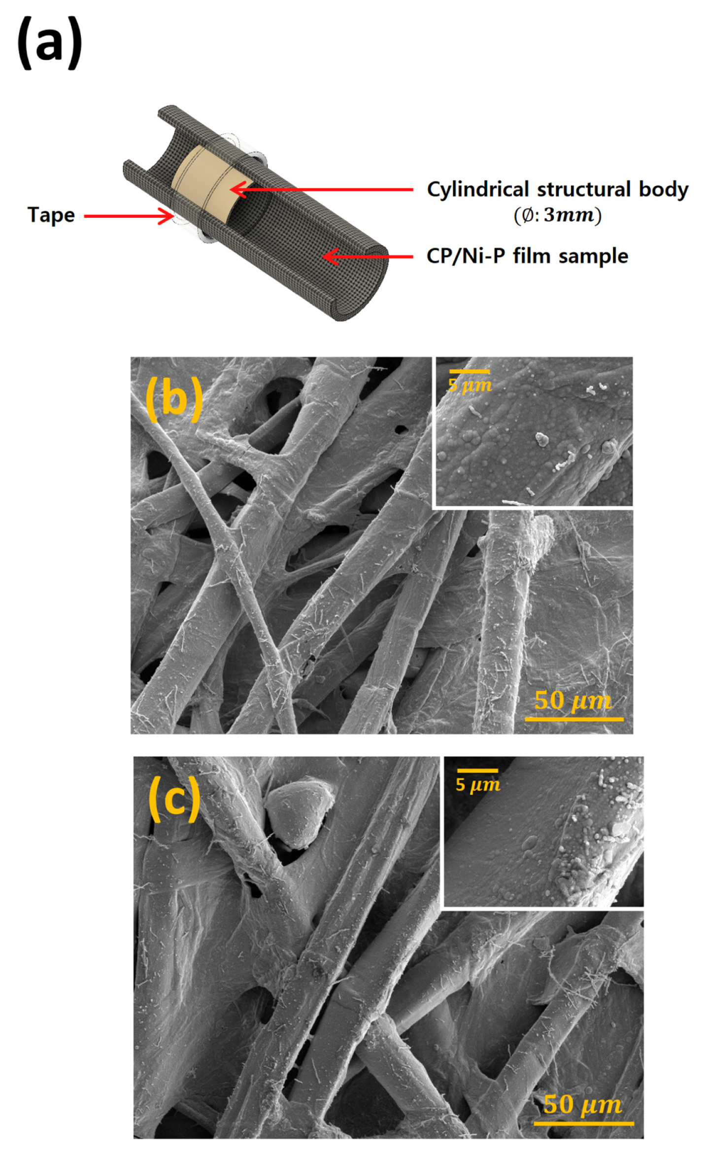
30] are typically used. However, because the samples fabricated in this study had the constraint of having a film layer formed on microfiber, it was difficult to obtain meaningful results using the conventional adhesive-strength tests. Instead, this study attempted to indirectly confirm the adhesive strength by observing whether the Ni-P film coated on the microfiber maintained its structural integrity when the fabricated samples were bent. As shown in
Fig. 4(a), the bending test was performed by wrapping a cylindrical structural body with a diameter of 3 mm with the CP/Ni-P film samples. To check for damages caused to the film after bending, it was separated from the structural body, and the morphology of the part of the plated layer that was bent was observed with an electron microscope. Compressive and tensile stresses acted on the inner (
Fig. 4(b)) and outer (
Fig. 4(c)) parts of the coated layer, respectively; the parts did not separate, and no micro-cracks of any kind were observed via electron microscopy.
The CP/Ni-P film samples fabricated above were tested as anode active material for Li battery. Typically, when an active material is coated on a metal substrate, an increase in the thickness of the active material results in an increased capacity, and it also increases the electron migration distance that, in turn, leads to overvoltage, thereby causing a negative impact on the rate properties. Additionally, the contact resistance between the substrate and active material can hinder high-rate operation. However, in the electrode fabricated in this study, there was no actual contact resistance between the substrate (Ni) and active material (Ni-P) because they exist in a single form and exhibit excellent electron mobility. Thus, from a materials engineering perspective, the fabricated Ni-P film assembly can be considered an ideal form of an electrode.
Because the amount of P, the active element in the fabricated Ni-P film, was not large, it is difficult to expect a significant effect on the capacity per weight. In other words, when rough calculations were made based on the results of weight and component analysis (
Fig. 2) under the assumption that all P present in Ni-P film reacted with Li; NiP3, NiP6, and NiP10 were estimated to have a specific theoretical capacity of 42 mAhg
ŌłÆ1, 99 mAhg
ŌłÆ1, and 195 mAhg
ŌłÆ1, respectively. These results showed that even the specific capacity with the highest P content (NiP10) did not reach the level of graphite (372 mAhg
ŌłÆ1). However, the situation is different when considering the capacity per physical area (mAhcm
ŌłÆ2), which is one of the key indicators in film electrodes. As shown in
Table 2, the theoretical capacity per physical area of all samples fabricated in the present study was much higher than hypothetical pure graphite film (84 mAhcm
ŌłÆ2 = 372 mAhg
ŌłÆ1 ├Ś 2.27 gcm
ŌłÆ2 (density) ├Ś 1 mm (thickness)) having the same thickness. As compared to that of hypothetical pure P film (472 mAhcm
ŌłÆ2 = 2596 mAhg
ŌłÆ1 ├Ś 1.82 gcm
ŌłÆ2 (density) ├Ś 1 mm (thickness)), the theoretical areal capacity of our samples is almost equal (NiP3) or higher (NiP6 and NiP10). It is noteworthy that the thickness of the CP adopted in this work is only 100 ╬╝m. One can easily increase the areal capacity of CP/Ni-P film by selecting thicker CP having more fiber strands. The above results imply that the fiber/Ni-P film fabricated in this study can be a promising option for a power source of wearable electronic devices, for which the capacity per physical area is an important factor.
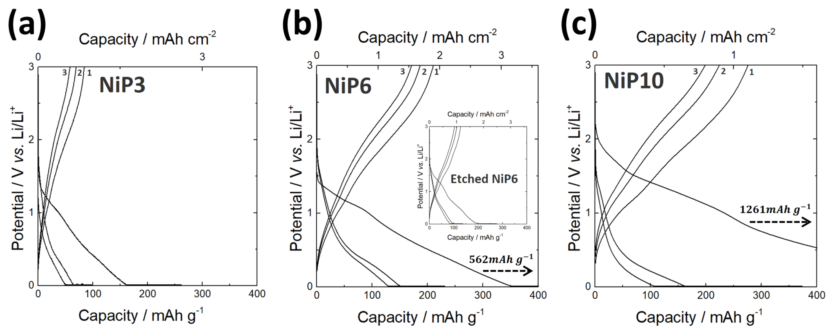
Fig. 5 shows the charge/discharge curves for the first three cycles of three different samples with varying P content. Large irreversible capacity loss was seen in the first charge/discharge process, similar to the previous works on the anode that reacts with Li according to a conversion mechanism [
31ŌĆō
34]. It is generally believed that such an initial capacity loss is mainly caused by the decomposition of electrolyte, forming a solid electrolyte interphase (SEI) on the electrode surface, and partially attributed to the irreversible insertion of Li ions into the Ni-P [
35].
Notably, all the samples were reversibly charged/discharged in the subsequent processes. It should be mentioned that the areal discharge capacity values of all three samples were higher than the theoretical capacity presented in
Table 2. This higher value might be attributed to the presence of NiO on the film surface and this possibly provides additional capacity by the reaction between NiO and Li [
36]. In order to confirm the above arguments, the charge/discharge experiment was conducted on samples with NiO removed from the surface by chemical etching. The result showed a dramatic decrease in reversible discharge capacity close to the theoretical one (inset in the image of
Fig. 5(b)).
Fig. 6 shows the capacity retention of three samples during 20 cycles of charge/discharge. As P content decreased, the capacity retention increased. Nevertheless, even in the case of the sample with the lowest P content (NiP3), the capacity retention was not so satisfactory.
Active materials, such as Ni-P, which undergo reaction by conversion mechanism, tend to show structural failure due to volumetric change during alloying/dealloying with Li [
37]. To analyze whether such structural failure could be a cause of the decline in lifespan properties, changes in structural integrity and morphology of Ni-P film were analyzed after the cycling test. As shown in
Fig. 7(a), NiP3 with relatively low P content showed almost no change in surface morphology after cycling. However, as the P content increased (NiP6 and NiP10), the surface became very rough after charge/discharge (
Figs. 7(b),(c)). It is believed that this is due to the relatively large amount of P reacting repeatedly with Li and thus severe local expanding and shrinking of the film. Besides, the SEI growth on the surface became more severe. Despite such changes in surface morphology, all three samples showed no separation of the plating layer, and no detectable micro-cracks were found in electron microscopy.
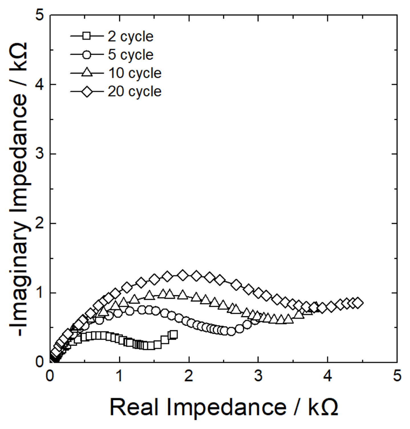
Fig. 8 shows the changes in impedance with the increasing number of cycles. After 20 cycles of charge/discharge, interfacial resistance (arc size on Nyquist plot) increased by approximately 3-fold. As mentioned above, if physical changes during charge/discharge, such as separation of the film layer or micro-cracks are minimal, then an increase in the interfacial resistance may be attributed to excessive growth of the SEI layer.
To improve the lifespan properties under such a situation, the capacity retention rate was observed while increasing the charge cut-off voltage (lower-limit voltage) from 0.01 V vs. Li/Li
+ to 0.1 and 0.3 V vs. Li/Li
+. In other words, since most of the SEI formation reaction is believed to occur below 0.8 V vs. Li/Li
+ [
38], increasing lower-limit voltage could reduce undesirable growth of the SEI layer.
Figs. 9(a-1), (a-2) show the typical charge/discharge curves of NiP3 for the first three cycles when charge cut-off voltage was adjusted.
Fig. 9(b) shows the capacity retention during 20 cycles of the charge/discharge under corresponding charge conditions. As the cut-off voltage was increased, the capacity retention rate increased significantly. Although the cycling performance needs to be further improved from the practical viewpoint, it is noted that the discharge capacity per physical area at the 20th cycle maintained to be comparable to the capacity of hypothetical pure P film electrode having the same thickness (presented in figure), in spite of the reduced operating voltage range.
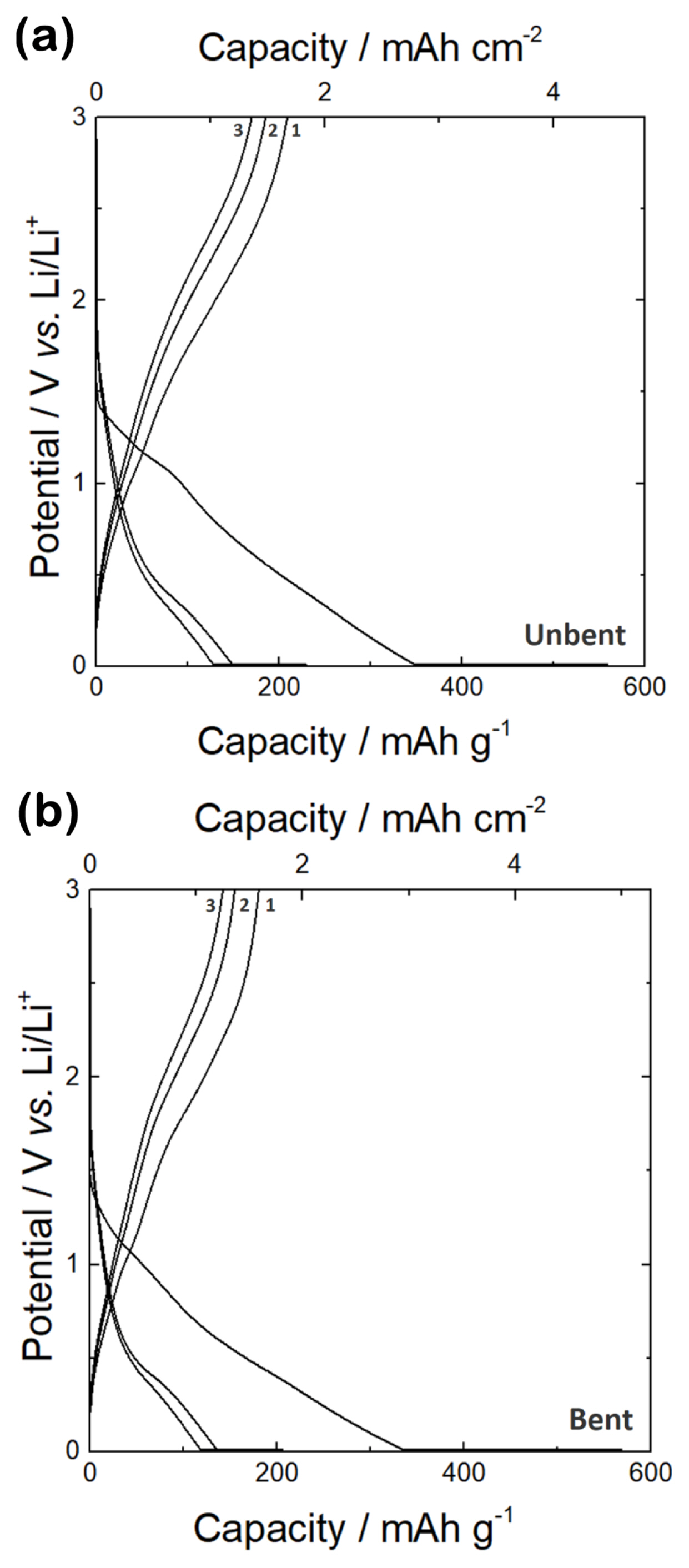
Lastly, the bending test was performed to determine the applicability as a power source for wearable devices. The CP/Ni-P film samples were bent by wrapping them around a cylinder having a diameter of 3 mm. When the charge/discharge experiment was conducted on the bent samples, the results were just about the same before and after bending with respect to the overall shape of voltage curve and capacity (
Fig. 10).