1. Introduction
Supercapacitors or ultracapacitors have emerged as promising eco-friendly alternative for energy storage applications. These work on the principle of electric double layer formation by accumulation of charges at the interface between electrodes and electrolytes which demands high specific surface area and stable electrode materials. Carbon, because of its bulk abundance, fair conductivity, chemically and potentially stable nature in electrolytes is the most common choice as electrode materials [1]. Various carbon nano-materials, such as activated carbon [2], carbon nano-fiber [3], meso porous carbon spheres [4], carbon aerogel [5], graphene [6] and carbon nano tube [7] have been reported in literature. The electrode material characteristics mainly govern the energy storage and power output of the devices which are intensely dependent on charge uptake and ion diffusion capability of the electrode/electrolyte interface. Carbon aerogels have been a favored choice due to their multiple features such as large surface area, tunable pore size, open pore structure, moderate conductivity and cost. Many researchers have focused to improve surface area, mesoporosity and conductivity of carbon aerogels by varying synthesis parameters that influence nucleation, growth and interconnectivity of primary particles [8]. Even though being advantageous as a tailored material, the conductivity of resorcinol–formaldehyde (R-F) derived carbon aerogels (CA) is still rather limited that hinders their utility in various applications [9,10]. Consequently, many researchers made efforts for improving its conductivity by introducing high temperature graphitization, nitrogen doping etc. However, these treatment strategies were observed to have counter effect on surface area and porosity of carbon aerogels [11,12]. Recently, additive integration approach has been reported by many researchers for aqueous medium based resorcinol-formaldehyde carbon aerogel (CA) using additives such as CNTs, carbon fibers, graphene, conducting carbons etc. during sol–gel reaction [13–15]. The randomly distributed additives like carbon fibers and CNTs provide mechanical strength and conductive crosslinking across CA [16]. Conductive graphene oxide additive due to presence of large number of hydrophilic functional groups help in cross linking of R-F clusters leading to reinforcement of CA structure [17]. The conducting carbon black as additive has been reported by some researchers for improvement in conductivity which works as ‘shape-directing’ agents during polymerization stage. In addition, the presence of these additives suppresses the formation of the hydroxyl methyl derivates responsible for cross-linking of the structure, generating less branched larger clusters leading to higher mesopore volumes [18]. However, the commonly employed additives like Vulcan XC-72, Conductex SC having conductivity ~200 S/m, offer moderate specific surface area ~250 m2/g [19]. In the present studies, a conducting porous carbon developed in-house with comparatively larger surface area has been utilized as additive. This carbon material was synthesized in iso-propyl alcohol (CA-IPA) under modified gelation conditions at ~130°C under pressurized conditions and showed total surface area (~700 m2/g) and resultant conductivity ~290 S/m. These surface area properties indicate that CA-IPA is a form of carbon aerogel having different morphology [20]. CA-IPA was introduced as additive with the objective of improvement in conductivity and surface properties of routinely synthesized aqueous medium based resorcinol-formaldehyde carbon aerogel. The R-F gel obtained with addition of CA-IPA was dried under ambient conditions followed by pyrolysis and surface activation to yield composite carbon aerogel (CCA). In this work, various samples were prepared using additive in different proportions and their effect on surface area, mesoporosity and conductivity has been studied. Electrochemical properties have also been investigated to study the effect of additive on specific capacitance and electrochemical series resistance (ESR).
2. Experimental Details
2.1 Carbon Aerogels synthesis
Aqueous solvent based carbon aerogel was synthesized by sol-gel polymerization of resorcinol (R) and formaldehyde (F) in the similar manner as reported earlier [21]. The ambient pressure dried organic gel was pyrolyzed at 800°C in argon atmosphere to obtain carbon aerogel and further treated under controlled atmosphere of CO2 gas at 900°C for a period of ~4 hours to produce high surface area carbon aerogel (CA-W) [22]. The additive, CA-IPA was synthesized by polymerization of resorcinol (R) and furfuraldehyde in isopropyl alcohol medium under 130°C and pressure (2 M Pa) for 48 h in stainless-steel high-pressure vessel and the gel obtained was dried under ambient conditions. CA-IPA was obtained by pyrolysis of dried gel at 800°C followed by activation treatment at 920°C under controlled atmosphere of CO2 for ~2 hours [23].
Composite carbon aerogel samples were prepared by mixing CA-IPA as additive during gelation stage of CA-W. CA-IPA powder was grinded to ~30 micron size and mixed in different proportions with weight percentage of 2%, 4%, 6%, 8% and 10%. After additive induced gelation, all the steps of CAW synthesis were repeated to obtain the composite carbon aerogels termed as CCA-x, where x denotes weight percent of CA-IPA powder.
2.2 Physical & morphological characterizations
Surface properties of carbon aerogel (CA-W) and composite carbon aerogel (CCA) samples were measured by surface area analyzer (Micromeritics-ASAP-2020) using N2 adsorption technique. Total surface area was measured by BET (Brunauer-Emmett-Teller) method while pore size distribution and average pore diameter were measured by the BJH (Barrett-Joyner-Halenda) method. SEM micrograph of CA and CCAs were obtained by FESEM – Sigma (Zeiss). XRD patterns and Raman spectrographs of samples were obtained by RIGAKU diffractometer and Raman system (Wi-Tec) respectively. Conductivity measurement was carried out by pressure-based equipment similar to that reported by Celzard et al. [24].
2.3 Electrochemical characterizations
Electrochemical characterization of CA-W, CA-IPA and CCA sample electrodes were performed using electrochemical potentiostat (Autolab) for cyclic voltammetry (CV) and impedance spectroscopy. The electrodes were prepared by applying coating of the respective sample on the graphite surface using polyvinyl alcohol binder [25]. Measurements were performed in 1 M H2SO4 electrolyte with Ag/AgCl as reference in three electrode system [26]. Average specific capacitance (C) of these samples was calculated from voltammogram obtained at different scan rates using Eq. (1).
Here, specific capacitance (C) is represented in farad per gram for voltage range (dv) of 1 volt at scan rate (S) expressed in milli-volt per second with mass (m) in gram and cathodic (Ic) and anodic current (Ia) in ampere. Nyquist plot was obtained using frequency response analyzer for equivalent series resistance (ESR) measurements. Rate capability and cyclic stability of these samples were also evaluated by galvanostatic charge/discharge for 1-volt potential range at different current densities.
3. Results and Discussions
3.1 Physical & morphological characterizations
Surface area analysis of CA-W, CA-IPA, and CCA samples were performed and their surface properties are shown in Table 1. Specific surface areas of CA-W and CA-IPA are 1689 m2/g and 876 m2/g with mesoporous areas of 578 m2/g and 478 m2/g respectively. Though the BET surface area of CA-IPA is less compared to CA-W, it has significant mesoporous contribution. In-situ mixing of CA-IPA in different proportions (2 to 10%) in CCA-x during gelation of CA-W alters the polymerization chemistry which is reflected in their surface properties. Total surface area, mesopore area and total pore volumes of CCA samples show increase with increasing additive proportion. Maximum total surface area and mesopore area of 2056 m2/g and 827m2/g was obtained respectively for CCA-8 along with improved total pore volume of 2.41 cm3/g. Electrical conductivity of these samples is also shown in table 1. CA-IPA is used as conducting additive having conductivity of 286 S/m. Gradual increase in conductivity was observed for composite samples by increase in additive percentage except for CCA-10 in which gelation was incomplete. Maximum improvement in conductivity of 48% was measured for CCA-8 in comparison with CA-W.
N2 adsorption-desorption isotherms of various carbon aerogels and composite samples are shown in Fig. 1(a). Quantity adsorbed for CA-IPA is much lower than CA-W at all pressure points indicating relatively lower total surface area. All the samples including CCA exhibited type IV isotherm with prominent hysteresis loops which is a characteristic of mesoporosity. Distinct curvature and shape of hysteresis are due to different shape, size and arrangement of carbon nanoparticles and pores. Onset of hysteresis for CA-W and CA-IPA at 0.6 and 0.4 relative pressure indicates that CA-IPA has smaller mesopores. CCA isotherms show increase in adsorbed gas volume compared to CA-W likely due to alteration of carbon particles arrangement and pore structures with additive incorporation. The presence of additives slows down the polymerization of intermediate particles leading to large pore volume and higher mesoporous area. For CCA-2 and CCA-4, shape of isotherm is closer to CA-W and at higher percentage the deviation is increased. Quantity adsorbed as well as surface area of CCA increases linearly up to CCA-8. However, for CCA-10 the isotherm behavior is deformed with much lower hysteresis. BET surface area of CCA-10 was observed to be 1097 m2/g along with reduced mesoporous area and total pore volume. This may be due to the non-uniform dispersion of additive in R-F solution resulting in carbon aerogel with inferior properties. The pore size distributions shown in Fig. 1(b) were obtained by the desorption isotherms using BJH method. CA-IPA has pores dispersed with full range up to 40 nm while CA-W and CCA samples show predominant peak at pore size of ~ 15 nm. Peak positions of CCA are slightly shifted to larger pore diameter with increase of additive. For CCA samples, total pore volume increases gradually with additive and for CCA-8 pore volume of 2.41 cm3/g was obtained which is much higher than respective value of 1.61 cm3/g for CA-W. Two representing samples CCA-4 & CCA-8 along with CA-W and CA-IPA have been chosen for further morphological and electrochemical characterizations.
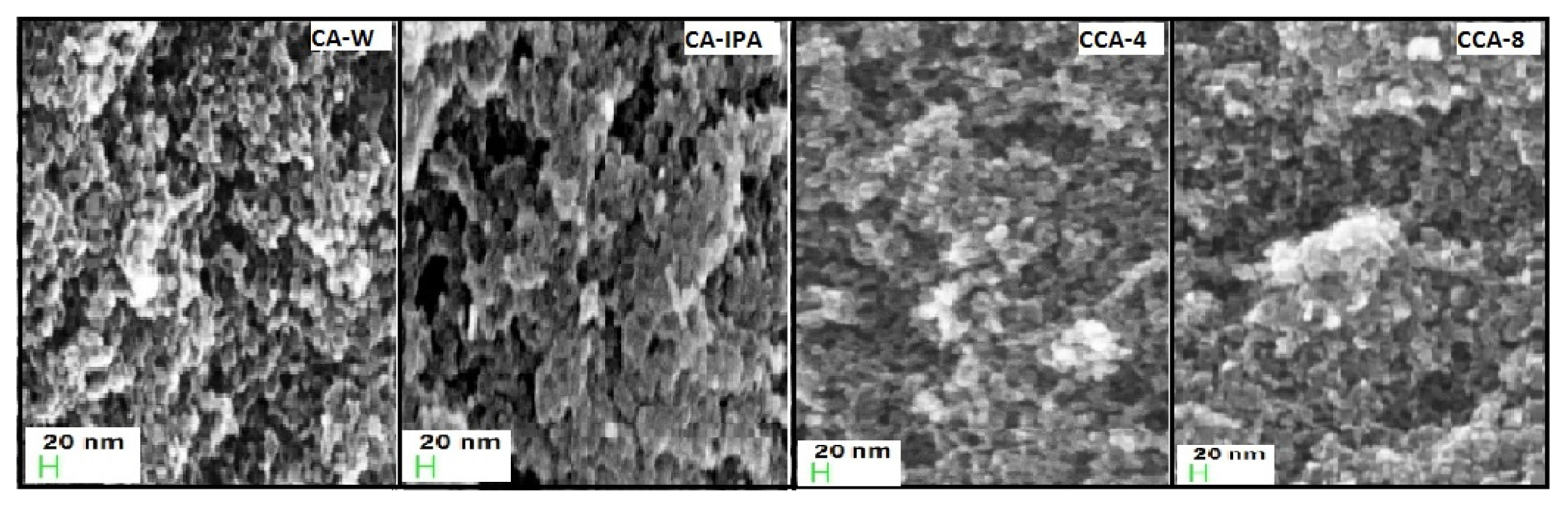
The scanning electron micrographs of CA-W, CA-IPA, CCA-4 and CCA-8 are shown in Fig. 2. It is seen that all micrographs show clusters of interconnected carbon nanoparticles of different diameters arranged in continuous porous network. Image for CA-W shows evenly distributed mesopores with uniform structure of carbon matrix while densely packed flakes layered structures are observed for CA-IPA. The heterogeneous growth is observed in CCA samples and the effect is more predominant in CCA-8 leading to enhanced porosity and accessible surfaces.
The XRD spectra of CA-W, CA-IPA and CCA-8 are shown in Fig. 3. Broad diffraction peaks observed at 2θ = 26° & 43° for these samples correspond to (002) & (101) planes of graphitic carbon. The peak of CA-IPA additive being sharper at both planes signifies higher degree of graphitization [27]. Slightly prominent peaks of CCA-8 compared to CA-W indicate structural changes and graphitic nature due to incorporation of CA-IPA. For further investigation of structural analysis, Raman spectroscopy of these samples was carried out. The first-order spectrograph of CA-W, CA-IPA and CCA-8 are shown in Fig. 3 which resemble the typical profiles of amorphous carbons. The two broad bands observed at 1354 cm−1 and 1590 cm−1 are assigned, respectively to the disorder-induced with the lack of long-range translation symmetry (D band) and to the in plane displacement of carbon atoms in the graphene sheets (G band) [28]. I(D)/I(G) ratios were measured by deconvolution of these bands for comparative evaluation of degree of graphitization of samples. I(D)/I(G) ratio for CA-W, CA-IPA and CCA-8 are 2.83, 2.61 and 2.73 respectively. The observed lower I(D)/I(G) ratio for CCA-8 compared to CA-W, infers higher structural order provided by modified gelation. The lowest I(D)/I(G) ratio for CA-IPA assigned to its relatively ordered structure. Raman analysis and XRD results are concurrent with the conductivity measurements.
3.2 Electrochemical evaluations
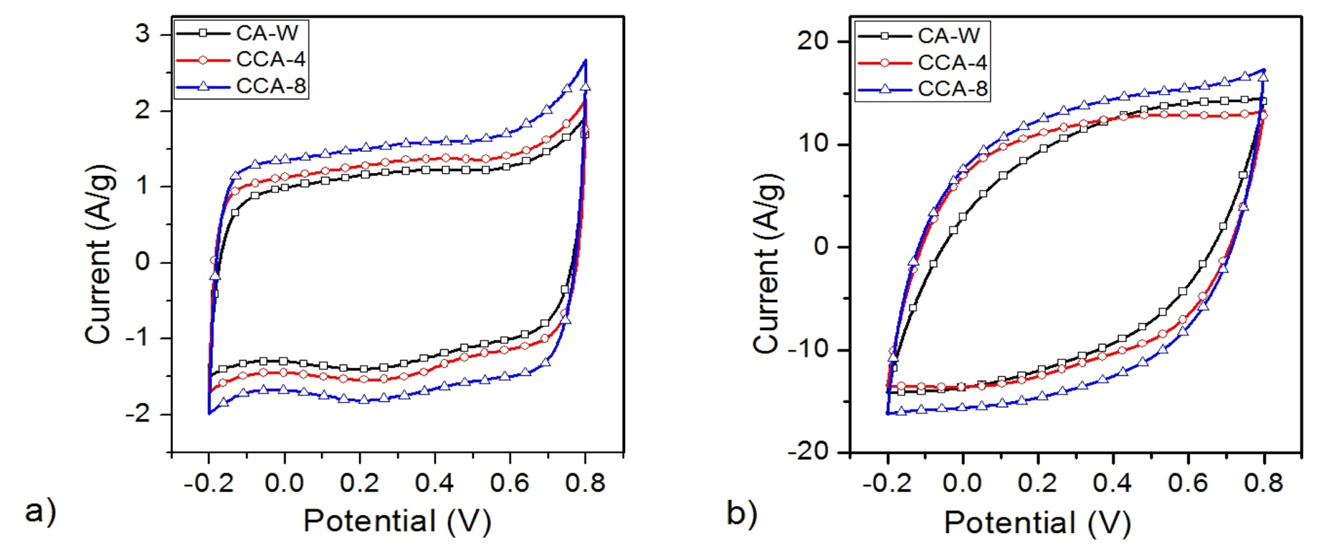
Voltammograms of CA-W and composites CCA-4 & CCA-8 shown in Fig. 4 were obtained by cyclic voltammetry performed at 10 mV/s and 100 mV/s scan rate. Nearly rectangular voltammograms of these samples at lower scan rate of 10 mV/s represent the good capacitive nature with complete electric double layer formation even in larger micropores. Using Eq. (1), specific capacitance evaluated for CAW is 112 F/g and for CCA-4 and CCA-8 are 128 F/g and 148 F/g respectively.
Many researchers have reported work on variety of composite carbon xerogels with different additives. Rodriguez et al. reported use of graphene oxide and carbon black additives with specific capacitance of 130 F/g and 112 F/g respectively [29]. Composite carbon aerogel with multi-walled carbon nanotubes (MWNT) have been reported in literature with specific capacitance as high as 211 F/g [30]. In another report, carbon aerogel using diatomite additive and hydrofluoric acid etching is reported to have capacitance of 59 F/g [31]. Carbon black additive based carbon aerogel synthesis was also reported by Macias et. al and with specific capacitance of 120 F/g [18]. Additives such as graphene, CNTs and carbon black are high conducting carbon materials commonly used for composite purposes. In the present study, a in-house synthesized CA itself having much higher conductivity and different morphology has been used as an additive. The resultant composite carbon aerogel termed as CCA showed improvement in mesoporosity, conductivity with much higher specific capacitance of 148 F/g.
Improvement in specific capacitance of CCA is correlated with the increase in specific surface area due to structural changes leading to higher surface area. As seen in Fig. 4 (b), the shapes of voltammograms at higher scan rate of 100 mV/s are more rectangular shaped for CCAs in comparison to CA-W which may be attributed to higher mesopores which offer easy transport of ions at higher scan rates [32].
The Nyquists plots of CA-W, CCA-4 and CCA-8 obtained from EIS measurements are shown in Fig. 5 for frequency range of 100 kHz to 10 mHz. In the inset, enlarged view of respective curves around the knee frequency are shown. Typically, Nyquist plots have semicircle in high frequency region and straight line in low frequency region which is a characteristic for an ideal capacitor. The intersection of extrapolated straight line on real impedance axis represents the equivalent series resistance (ESR) of materials [33]. It is seen that, while CA-W showed highest ESR with value of ~1.9 Ω, as compared to CCA samples. The observed values of ESR for CCA-4 and CCA-8 were 1.5 Ω and 0.9Ω respectively. Significantly lower ESR for CCA-8 is attributed to its higher electrical conductivity. The key characteristics of CCA-8 with ESR < 1 ohm in combination with high specific surface area of >2000 m2/g make it a useful material specially for the energy storage application.
The galvanostatic charge/discharge (GCD) of CAW, CCA-4 and CCA-8 samples performed at constant current density of 1 A/g are shown in Fig. 6(a). The curves of CA-W & composites are virtually linear and symmetric indicating a good reversibility and excellent capacitive properties. Rate capability of the samples were evaluated by observing variation of specific capacitance at different discharge current. Specific capacitance values of different samples obtained for variation of discharge current densities from 1 to 10 A/g are shown in Fig. 6(b). These specific capacitances were evaluated from the discharge profiles obtained at respective current densities. Though the rate capability pattern for all the samples show a similar decreasing trend with increasing current densities, CCA-8 exhibited marginally lower variation which is supported by nearly rectangular cyclic voltammogram at higher scan rate.
Cyclic stability testing of CA-W, CCA-4 and CCA-8 samples was measured by repeated GCD performed at constant current density of 1 A/g in 1 M H2SO4. The results of 1000 cycles are presented in Fig. 7 which shows good stability with nearly 100% capacitance retention indicating good electrochemical stability of CA as well as its composites.
4. Conclusions
Incorporation of graphitic and porous carbon as additive having different morphology led to altered pore size distribution which enhanced conductivity and meso-porosity of composite material. Mixing of additive during polymerization did not behave as mere addition of the properties of two types of carbon aerogels but resulted in CCAs as new class of carbon aerogel. CCA-8 was found as an optimum composition with maximum improvement in BET surface area from 1689 to 2056 m2/g, mesopore area from 578 to 827 m2/g and ~ 46% increase in electrical conductivity as compared to CA-W. The high specific capacitance for CCA-8 compared to pure CA-W is ascribed to improved surface area, mesoporosity and conductivity. The observed specific capacitance of 148 F/g and ESR of < 1 Ω along with good cyclic stability make this composite material a better choice as electrode for energy storage applications.