1. Introduction
Redox flow battery is suitable for a large energy storage device in connection with renewable energy, and various redox flow battery systems are configured according to the type of electrolyte such as iron/chromium, bromine/polysulphide, vanadium/bromine, zinc/bromine, zinc/cerium, and vanadium redox couples [1–3]. Among the electrolyte candidates, the vanadium redox flow battery (VRB) has been close to commercialization with excellent performance. Fig. 1 shows a typical VRB single cell structure, in which the bipolar plate and the electrode are assembled with the mechanical pressure around the separator. In here, the redox reactions of vanadium electrolyte, V(IV)/V(V) and V(II)/V(III), are occurred at the positive and the negative electrode, respectively [4–5]. In here, when the mechanical pressure is decreased by physical factor such as vibration and electrochemical factor such as corrosion and decomposition during operation, large internal resistance which leads to degraded performance of the VRB will be originated at the interface between the electrode, the bipolar plate, and separator. Also, VRB performance is greatly affected by the bulk resistance of the electrode and bipolar plate, and the contact resistance between them. Therefore, electrode and bipolar plate are the key components in VRB systems. Generally, the graphitic types of bipolar plate and electrode were mainly used for vanadium redox flow battery because of preventing corrosion of bipolar plate by electrolyte and securing a certain level of electron conductivity for reducing the internal resistance of the battery [6–7]. The carbon bipolar plate has been fabricated by cutting of carbon from carbon bar or compression molding using mixture of a polymer binder and graphite. The contact of the existing electrode/bipolar plate is determined by the fastening pressure during assembly in the form of single cell/stack. At this time, depending on the fastening pressure of the cell/stack, a trade-off problem has occurred between the contact resistance of the two parts, bipolar plate and electrode, and the fluidity of the electrolyte. Therefore, various studies have been conducted to reduce the contact resistance between the electrode and the bipolar plate [8–10].
As the most representative example, M. Kazaco et al. suggested a process of thermally bonded graphite felt on a carbon-plastic composite bipolar plate, and further improvements have been continued [11–14]. In addition, P. Qian et al. have conducted a study of applying an adhesive conducting layer between the bipolar plate and the electrode to bind the two parts with heat and pressure [15]. Herein, the bipolar plate is fabricated using flexible graphite, which is different from the existing studies using impermeable graphite. Moreover, adhesive conducting layer, which plays a vital role in electrode/bipolar assembly, is composed of thermo-plastic phenol formaldehyde resin (PF), carbon black, and graphite powder. According to the results of previous studies [15], when a thin flexible bipolar plate of carbon plastic composite type was applied on the graphite felt as electrode, several disadvantages have been come up such as high bulk resistance in bipolar plate, contact resistance between bipolar plate and graphite felt, and high manufacturing cost; moreover, contact resistance can be reduced by introducing an adhesive conducting layer composed of a PF-based conductive composite material between a thin flexible bipolar plate and graphite felt.
In this study, we focused on effect of ethylenevinyl-acetate (EVA) based conductive adhesive film (CAF) by coating conductive material such as carbon black (CB) and carbon nanotube (CNT). That is, CAF, which is non-woven fabric of hot melt adhesive (web type) coated CB (CB-EVA) and CNT (CNT-EVA), was fabricated by wet process. Bare EVA, CB-EVA, and CNT-EVA films were prepared and the through resistance of each film was measured. Moreover, they were applied between electrode (graphite felt) and the bipolar plates. Finally, the contact resistance, between the electrode and bipolar plate, and energy efficiency of VRB single cells were investigated by charging and discharging cycle in more detail.
2. Experimental
2.1 Fabrication and characteristics of conductive adhesive films
Three kind of conductive adhesive films, a non-woven EVA (ethylene-vinyl-acetate) material alone (bare EVA), coating of carbon black (CB-EVA) and coating of CNT (Carbon Nano Tube) (CNT-EVA) on bare EVA film, were prepared by wet dispersion process. To fabricate the bare EVA, CB-EVA and CNT-EVA film samples based on a non-woven hot melt EVA sheet, as starting materials, a non-woven hot melt adhesive (EVA W80, JCC KOREA. Co., Ltd, Korea), carbon black (Ketjen black 600JD, Mitsubishi Chemical, Japan), and CNT (WMCS-I-O, WONIL Corporation, Korea) were prepared, respectively. Firstly, 0.2 wt% CB was put into an ethanol solvent for CB suspension.
The carbon black suspension by wet dispersion process was prepared by mixing carbon black (CB) with an ethanol solvent to have a concentration of 0.2 wt% for CB-EVA film sample and the conductive material CNT was mixed with an IPA solvent to prepare a dispersion of 0.01 wt% CNT for CNT-EVA film sample. Herein, the hot melt adhesive film is composed of EVA material having a nonwoven fabric structure; The color is white, the thickness is 97 μm, the weight is 100 g m−2, the melting point is 90°C, and the viscosity is 85 Pa.s at 180°C. The hot melt EVA films were soaked in a dispersion solution containing CB or CNT for 30 min, and then dried at 60°C to fabricate a conductive adhesive film for integrating electrode and bipolar plate of VRBs. To evaluate the oxidation resistance of the EVA resin itself, they are immersed in a vanadium sulfate solution (0.1 M V2O5 and 3 M H2SO4) for VRB in an oven at 40°C for above 720 hrs, and then the color of the electrolyte was observed in time. For each film samples coated by the carbon black and CNT, the surface morphology was observed by optical microscope and SEM analysis. Moreover, in order to measure the through resistance of bare EVA film, CB-EVA film, and CNT-EVA film, four sheets of a nonwoven fabric for each film sample are stacked and compressed in the range of 60~340 kgf cm−2 at 25°C. Finally, the film samples were prepared with the dimension of 7 cm × 7 cm. Through resistance was evaluated using current and voltage application equipment (CP-323, 34401A, Agilent Technologies Inc, USA) and pressure equipment (Carver Inc, USA).
2.2 Fabrication and characteristics of integrating electrode-bipolar plate assembly
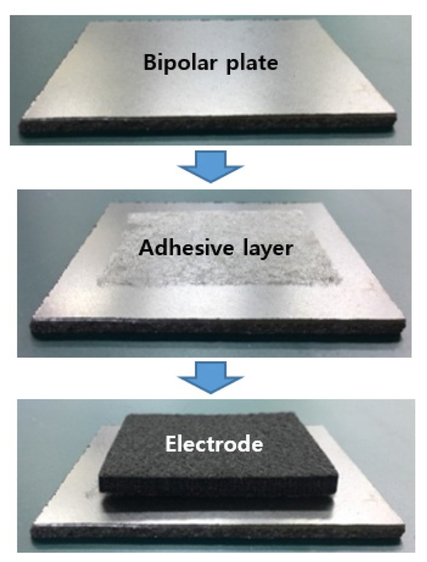
Fig. 2 shows the fabrication process of integrating electrode and bipolar plate with adhesive film. That is, after the adhesive films is placed between the bipolar plate and the carbon felt electrode, and a pressure of 0.5 MPa is applied at 110°C for about 1 min by a hot press device and then the integrating of bipolar plate-electrode is completed.
The contact resistance Rc between the integral electrode and the bipolar plate is defined as Rc = Rt x S, which is measured by multiplying the area and the sum of the contact resistance between the electrode and adhesive film, and between adhesive film and bipolar plate in the two current collectors (c1, c2) as shown in Fig. 3. Herein, the method of resistance involved measuring the potential difference across two current collectors, which sandwiched the sample, as a constant electrical current was passed through them. The variation in potential was recorded as the compaction force applied to the assembly was gradually increased. The contact area of the test sample was 49 cm2, and the applied compact pressure increased in the range of 5.5 to 13 kgf cm−2.
The tensile shear test is to measure the gripping strength of substrate by adhesive material as a load is applied to both ends of specimen. Herein, the shear strength was measured when electrode was pulled up from the bipolar plate-electrode assembly.
In order to fabricate VRB using an integrated bipolar plate and electrode assembly, the thickness of the bipolar plate is 3 mm, and the thickness and area of the electrode are 5.5 mm, and 25 cm2, respectively. Nafion 117 is used as a separator, and copper plates are placed at both ends as current collectors. The assembled VRBs were pressed with compact pressure of 11.12 kgf/cm2, respectively. The composition of the electrolyte solution of VRB was a mixture of 1.6 M VOSO4 and 2.5 M H2SO4. The amount of the electrolyte was 50 ml, and the flow rate was 30 mL min−1. The charge/discharge test of VRB single cell was conducted between 1.0 and 1.6 V at the room temperature, in which the cell was charged at constant current density (40 mA cm−2) to 1.6 V, kept at 1.6 V until 10 mA cm−2 and then discharged at constant current density (40 mA cm−2) to 1.0 V using a charge/discharge device (WPG100e, WonATech Co., Ltd, Korea).
The cell coulombic efficiency (CE) was defined as the discharge capacity divided by the charge capacity; the energy efficiency (EE) was defined as the discharge energy divided by the charge energy. Then the voltage efficiency (VE) was calculated from VE = EE/CE.
3. Results and Discussion
3.1 Characteristics of conductive adhesive films
Fig. 4 shows the chemical stability of the nonwoven EVA hot melt in electrolyte; it was checked whether this material is chemically stable after immersing in the electrolyte composition for VRBs for 720 hrs. In other words, Fig. 4 (a) shows the yellow color as a bare electrolyte and EVA sheet used for VRBs before test, and Fig. 4 (b) shows the characteristics that the color of electrolyte is almost unchanged even after the test, indicating that this material is very chemically stable in electrolyte. Fig. 5 shows the surface morphology of each adhesive film by optical microscope and SEM, respectively.
Fig. 5 (a) is a bare EVA film sample, which is a fine structure of EVA resin itself and has a white color in the form of a non-woven fabric. Fig. 5 (b) shows the microstructure of the bare EVA film sample, and the thickness of the adhesive wire formed as a non-woven structure was made to be about 50 μm, showing a clean surface condition. Fig. 5 (d) show the state of carbon black coating on EVA nonwoven fabric as a microstructure of CB-EVA film sample. It seems that a large amount of carbon black is coated on the hot melt wire irregularly, but CB-EVA has a uniform black color as shown Fig. 5 (c). Fig. 5 (f) shows the microstructure of the CNT-EVA film sample, where CNTs are uniformly coated on the EVA wire, and the coating layer has a relatively small amount of coating and looks thinner. Herein, since CNT is relatively expensive, the coating amount was adjusted to be relatively low. Thus, CNT-EVA has a light black color than CB-EVA.
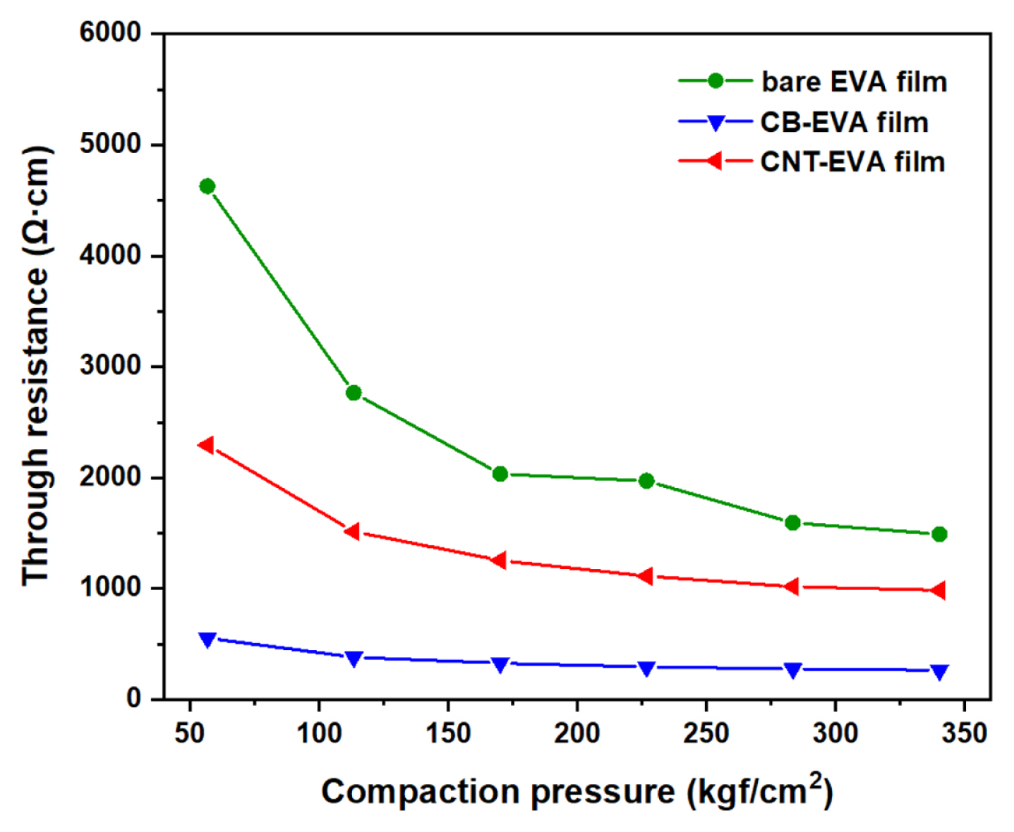
Fig. 6 shows the trend of through resistance according to the compaction pressure for each sample of the bare EVA film, CB-EVA film, and CNT-EVA film. This data was measured at room temperature by stacking and pressing four sheets of each sample using the equipment of KATECH (Korea Automotive Technology Institute), which was conducted at a relatively high pressure to remove the contact resistance factor between adhesive film layers. As a result, bare EVA film sample, which has no conductive material, has the highest resistance, and, CB-EVA film sample has the lowest through resistance than CNT-EVA film. In addition, CB-EVA film sample has little resistance change with increasing compaction pressure, but CNT-EVA film sample tends to be constant at a pressure of 220 kgf cm−2 or more, and bare EVA film at 280 kgf cm−2 or more. It can be seen that apparently the through resistance is more dependent on the coating content of conductive material than on the material type being coated.
3.2 Characteristics of electrode-bipolar plate assembly with conductive adhesive film
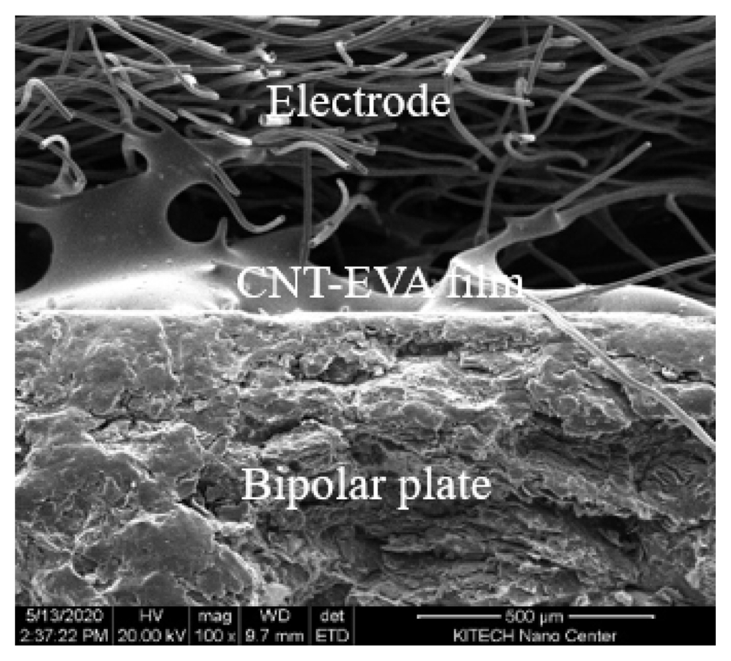
Fig. 7 shows the typicial microstructure of cross section of electrode-bipolar plate assembly with CNT-EVA film for VRBs. That is, it can be seen that the film connects the electrode and the bipolar plate well by adhesion. However, some of the film is pulled in the direction of the electrode when the compression of assembly is released before being sufficiently cooled after thermal compression. And unlike the bipolar plate, since the electrode has a porous structure to allow the electrolyte to flow, the adhesive surface on the electrode side is not uniform, and the conductive composition of adhesive film is expected to affect the contact resistance between the electrode and the bipolar plate. In particular, it can be found that despite a short thermal compression time, the non-woven EVA is sufficiently dissolved to a thickness of about 50 μm to maintain a wide adhesion surface.
Currently, the electrodes of commercial VRBs are maintained at a compaction pressure of about 0.5 to 7 kgf cm−2. The contact resistance of the existing electrode-bipolar plate shows 350 mΩ.cm2 at 1 kgf cm−2, and about 100 mΩ.cm2 at 5.5 kgf cm−2, respectively [16]. Fig. 8 shows the contact resistance of bare EVA assembly, CB-EVA assembly, CNT-EVA assembly, and blank cell without EVA as comparison: 175, 120, 75, and 139 mΩ.cm2 at 5.5 kgf cm−2, respectively, and tend to decrease with compaction pressure and finally it decrease to 80, 70, 50, and 74 mΩ.cm2 at 13 kgf cm−2. Comparing without EVA, contact resistance was decreased by introducing CAF such as CNT-EVA and CB-EVA. Herein, The CNT-EVA assembly sample showed the lowest value among the tested samples, and bare EVA assembly, which is not coated with a conductive material, showed the highest value. Thus, it seems that the contact resistance is dependent on the properties of the coating material on the non-woven EVA polymer. Although the EVA shape was non-woven type with large emty space as shown Fig. 5 (a), it was changed during compression under 0.5 MPa and 110°C as shown Fig. 7. Therefore, the contact resistance between the electrode and the bipolar plate varies with the coated materials.
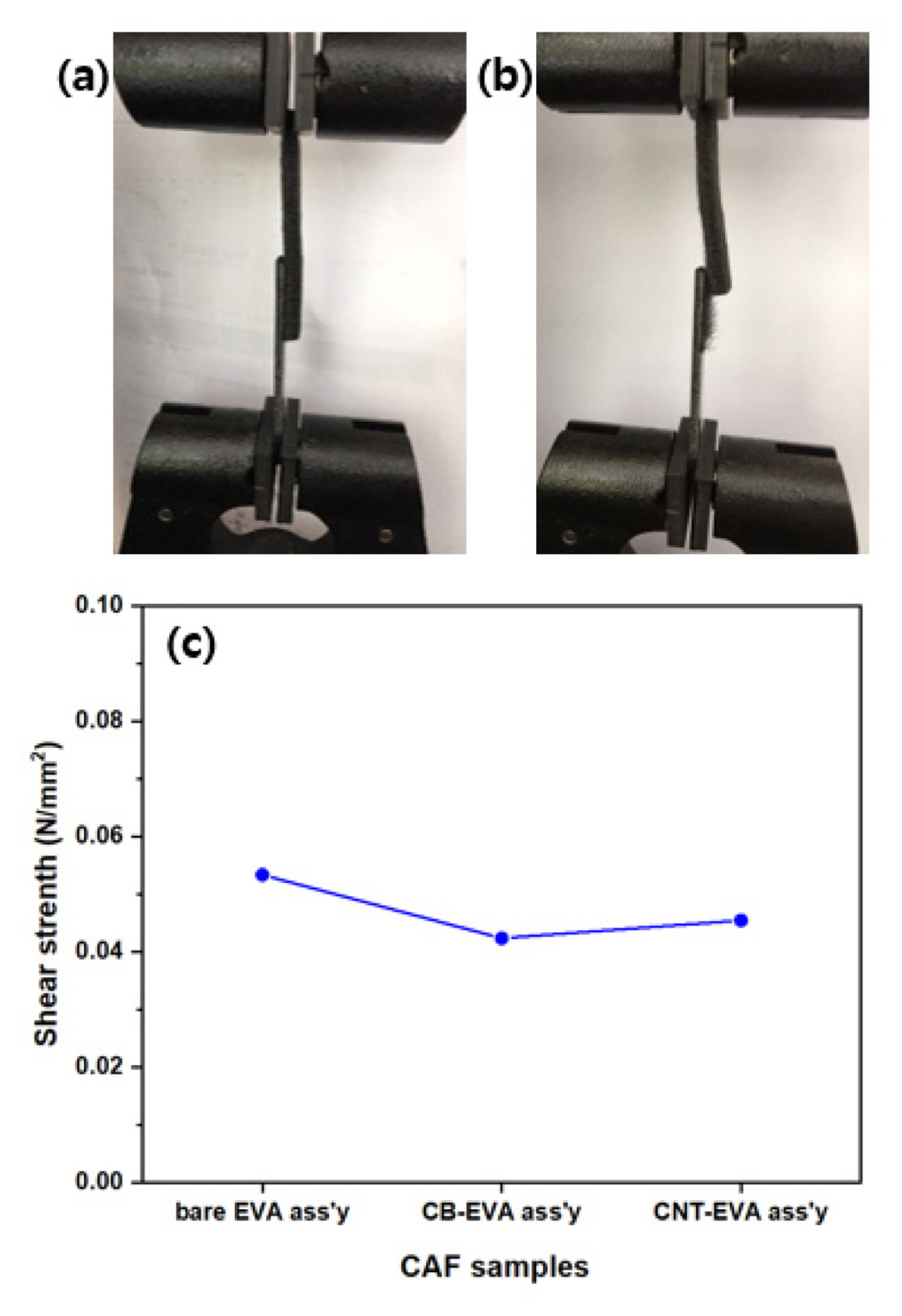
Fig. 9 shows the shape of the specimen before and after tensile test, and its shear strength of electrode and bipolar plate assembly. Fig. 9 (a) shows the state of samples in test device before test in which the electrode is well adhered with bipolar plate by adhesive film. Fig. 9(b) shows the status of the specimen after test, showing that the electrode is torn off on the bipolar plate. That is, it can be observed that some fabric wire of the electrode is remained on the bipolar plate. Fig. 9 (c) shows the shear strength of bipolar plate-electrode assembly according to the type of sample: bare EVA assembly is about 0.055 N mm−2, and the CB-EVA assembly and CNT-EVA assembly are 0.040, 0.045 N mm−2, which shows the behavior that the value of the CB-EVA assembly sample decreased slightly due to the relative increase in the content of conductive material.
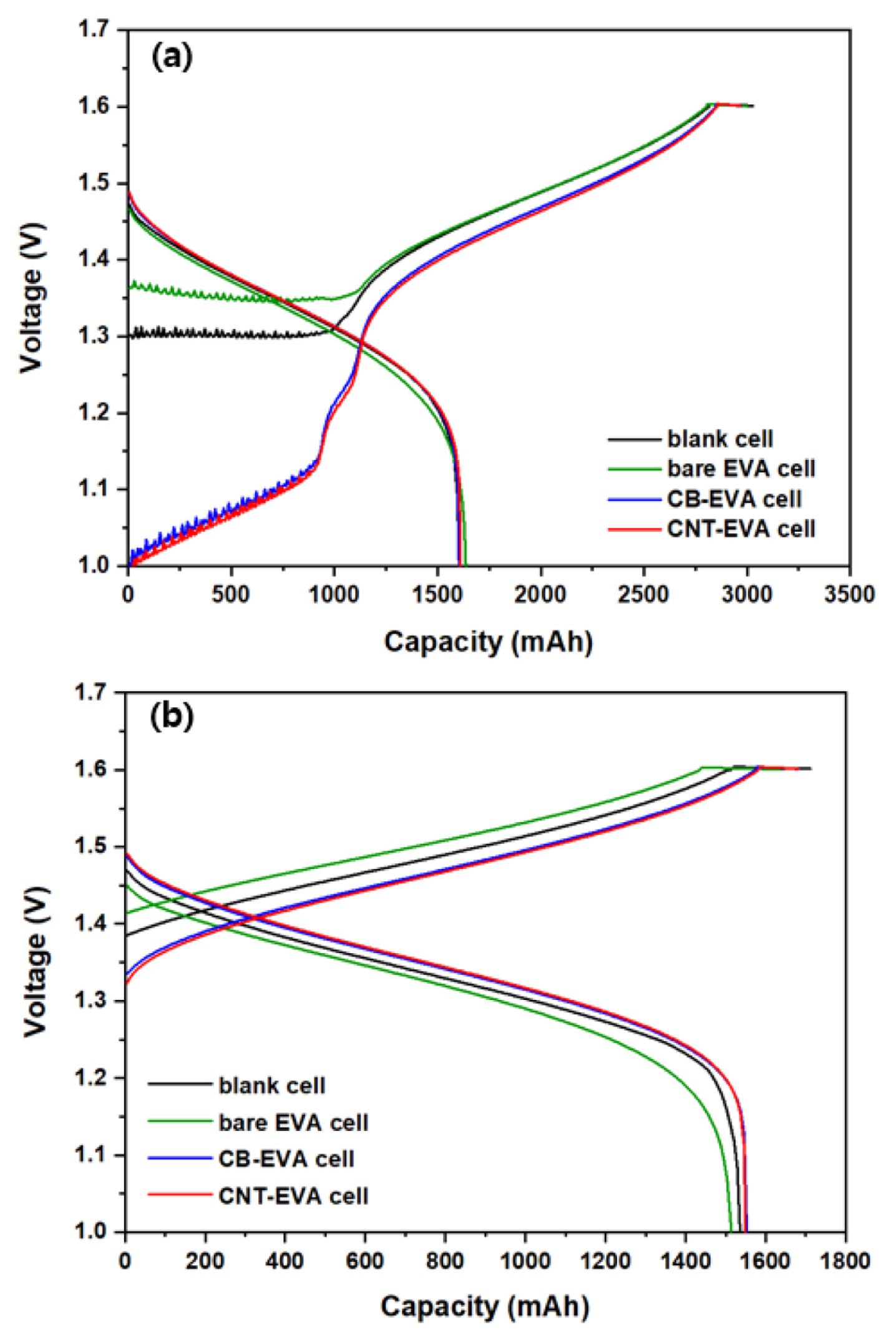
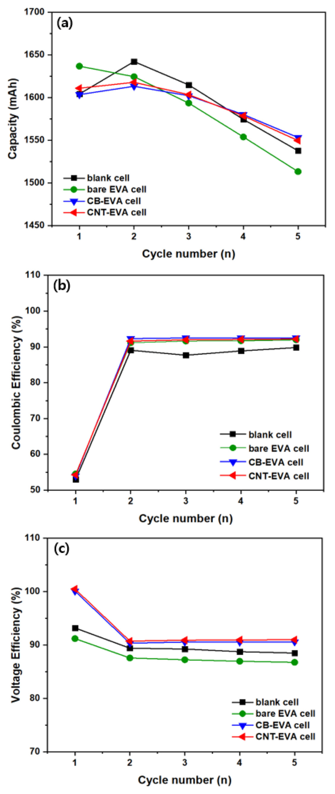
Fig. 10 shows the galvanostatic charge-discharge profile of VRB single cells by applying conductive adhesive films, including blank cell and bare EVA cell at 1st cycle and 5th cycle. Fig. 10 (a) shows the behavior of charge and discharge characteristics at 1st cycle for blank cell, bare EVA cell, CB-EVA cell and CNT-EVA cell, respectively. The OCV of the blank cell is about 1.3 V, the OCV of the bare EVA cell is about 1.36 V, and the OCV of the CB-EVA cell and CNT-EVA cell was equal to about 1.0 V. During the charging, the blank cell and bare EVA cell shows a relatively high overvoltage curve due to the internal resistance between bipolar plate and electrode. Moreover, it is reported that a large and irreversible charge curve was obtained at the first cycle, which is common to all the samples owing to the oxidation of V3+ to VO2 +/VO2+ during the initial charging process [17]. Fig. 10 (b) shows the charge/discharge curve of each cell at 5th cycle, and shows a different behavior from 1st cycle. That is, after 1st cycle, vanadium species were separated as the anolyte and catholyte, and the charge/discharge coulombic efficiency was nearly 100%. However, the average charge voltage of the blank cell was relatively increased and the discharge capacity was decreased as compared to CB-EVA cell and CNT-EVA cell, due to the increase in overvoltage during charging. In particular, bare EVA cell exhibited distinct overvoltage and voltage drop behaviors in both the charge and discharge curves due to the resistance of the adhesive film. Fig. 11 shows the cyclability, Coulombic efficiency (CE), and voltage efficiency (VE) of VRB single cells by applying different adhesive film during the cycles. It is clearly observed that cyclability of VRB was increased by introducing CB-EVA cell, and CNT-EVA with improved CE and VE. The VE tendency of VRB was exactly matched with the contact resistance tendency as shown Fig. 8. Therefore, decreasing contact resistance between bipolar plate and electrode affects for increasing VRB properties.
The efficiency of CE, VE, EE of the VRBs single cells at 5th cycle is summarized in Table 1. The EE of blank cell, bare EVA cell, CB-EVA cell, and CNT-EVA cell were 79.49, 79.82, 83.83 and 83.89%, respectively, and the EE value of CB-EVA cell and CNT-EVA cell were almost the same, indicating their high performance compared with that previously report of 81% at the same test condition [18]. In addition, it seems that CE of VRB single cell was increased by introducing EVA adhesive film compared to blank cell. Although the inhibition of corrosion of bipolar plates is not defined in this study, several studies suggested that protecting layer such as conductive polymer and mono polymer on bipolar plate affects the inhibition of corrosion of bipolar plates [19–22]. Similarly, the surface of bipolar plate was coated with EAV with a good chemical stability from electrolyte as shown Fig. 4. Therefore, we believe that the increased CE may be originated from coated conductive adhesive film on bipolar plate. Interestingly, the tendency of CE was similar to the tendency of through resistance. This is, the highest CE was achieved using CB-EVA adhesive film which showed the lowest through resistance of adhesive film. Thus, we expected that when through resistance of adhesive film is decreased, characteristics of electron transfer between bipolar plate and graphite felt is improved. It means that interface force at electrified interface like capacitance on surface of bipolar plate was decreased due to improved characteristics of electron transfer [23]. So that, probability of side reaction between bipolar plate and electrolyte was decreased. In the case of VE, VE of blank cell was also increased by introducing conductive EVA film coated with CB and CNT due to decreasing contact resistance between bipolar plate and graphite felt. The tendency of VE was also similar to the tendency of contact resistance of adhesive film. VE is indicated as overpotential and ohmic drop originated from vanadium redox reaction and internal resistance of cell. So, the highest VE was achieved using CNT-EVA adhesive film which showed the lowest contact resistance related to ohmic drop. Also, we expect that not only decreasing contact resistance by integrating electrode-bipolar plate, but CAF also can be work like electrode due to one of component is active materials such as CB and CNT. Therefore, by changing conductive material in CAF, overpotential properties originated from vanadium redox reaction can be changed.
In summary, it was found that the CB-EVA cell by carbon black coating increases CE, and CNT-EVA cell by CNT coating increases VE. In addition, it is very interesting that the contact resistance and the through resistance affect the efficiency characteristics of the VRB cells differently.
4. Conclusions
A non-woven sheet based on EVA (ethylene-vinylacetate) material was used as an adhesive film between the electrode and the bipolar plate, and then CB-AVA and CNT-EVA films were fabricated by coating carbon black or CNT to give conductivity on hot melt wire, including bare EVA film without any coating. Through the microstructure analysis of the adhesive film sheet, surface morphology of the nonwoven hot melt wire was observed, and the coating status of carbon black and CNT was well observed. To examine the effect of the coating composition of the hotmelt wire, the through resistance was measured on the bare EVA film and coating films at 25°C. That is, Among the samples, through resistance of CNT-EVA, contact resistance of CNT-EVA film were lowest value, respectively.
As a result of evaluation by applying each adhesive film to VRB single cells, the energy efficiency was obtained as 83.83% and 83.89% for the CB-EVA and CNT-EVA cells, respectively. In conclusion, it was found that CB-EVA film has an effect on Coulombic efficiency (CE) and CNT-EVA film has an effect on increasing voltage efficiency (VE) on VRBs. These results remind us that the CB-EVA film is related to the through resistance (voltage efficiency) and the CNT-EVA film is related to the reduction effect of the contact resistance (coulombic efficiency).