1. Introduction
Enabling the high-energy density Li-ion battery primarily relies on the use of high-capacity cathode and anode materials. Li-rich layered oxide, represented by xLi2MnO3·(1−x)LiMO2 (LMNC; M = Mn, Ni, Co), is a potential high-capacity cathode active material that delivers a high specific capacities ≥ 250 mAhg−1 when operating at high charge cut-off voltage ≥ 4.4 V versus Li/Li+, from which nearly doubled energy density from that of a LiCoO2-based battery is attainable. However, anodic instability of conventional carbonate-based organic electrolyte above 4.2 V versus Li/Li+ and unstable cathode-electrolyte interface at a highly charged state causes metal-dissolution event from cathode and consequent cathode degradation modes, deleteriously affecting cycling performance. Earlier report by Song et al. showed that the use of fluorinated linear carbonate as a novel high-voltage electrolyte additive enables the charge of Li-rich layered oxide cathode to higher voltages beyond 4.4 V [1–4]. Fluorinated organic carbonate compound enhances the stability of chemical bond nature and thus lowers the highest occupied molecular orbital (HOMO) energy level, which enhances the anodic stability of electrolyte [1–3]. Moreover, the additive can induce to form a stable surface protective fluorine-rich solid electrolyte interphase (SEI) layer and to improve high-voltage cathode-electrolyte interfacial stability [1–3]. Utilization of a small fraction of high-voltage additive(s) on the standard lithium salt concentration of 1.0 M LiPF6 and ethylene carbonate (EC)-based conventional liquid electrolyte is a cost-effective strategy for performance improvement while holding the major properties of the electrolyte.
Silicon (Si)-graphite anode active material has been studied and developed for decades for its potential applicability to high-energy density Li-ion battery. The Si represents a high-capacity anode material due to the high theoretical specific capacity of Si (3579 mAhg−1, when charged to Li 15Si4), which is more than 9-fold of the capacity of graphite (372 mAhg−1) [5–13]. As increasing the fraction of Si in the Si-graphite composite, capacity is expected to increase. However, it suffers from a rapid capacity fade because of a large volume change of Si up to 300%, and consequent particle pulverization, the loss of electrical connectivity, the destruction of the SEI and continuous electrolyte decomposition [7,13]. To accommodate the volume change of Si and to mitigate the failure modes of Si under the circumstance of using conventional binder and conventional electrolyte, the use of very limited fraction of Si is required [5,6,15,16]. Commercial LIBs therefore employs the Si content lower than 5 wt%. In addition, the SEI formation and stabilization technology is extremely important in achieving a good performance of Si-graphite anode [8–10]. Fluoroethylene carbonate (FEC) is a well-known SEI-forming agent on both Si and graphite, which has a lower the lowest unoccupied molecular orbital (LUMO) energy level than that of EC of conventional electrolyte. The working mechanism of FEC additive is well established as the occurrence of its electrochemical reductive decomposition earlier than EC at the surface of anode and the formation of FEC-derived organics and LiF-rich SEI layer [11,17,18]. Sometimes a large amount up to 20 wt% of FEC is added to conventional electrolyte as additive but it increases the weight of a whole battery, which in turn reduces the specific energy density of a whole battery [19–22]. The use of just one additive would be ideal but it often results in non-satisfactory performance of a full-cell [2,20] because it works on either cathode only or anode only, or on other property such as thermal stability of electrolyte, etc. In commercial LIBs, several additives are used to improve the performance, cycle-life and/or safety. Challenges to obtain a good cycling performance of a high-voltage full-cell of Si-graphite||Li-rich layered oxide using fluorinated carbonate additive(s) remain.
Herein, we report the effects of fluorinated dual-additives of fluoroethylene carbonate (FEC) and di-(2,2,2 trifluoroethyl)carbonate (DFDEC) at optimum fractions in the electrolyte of 1.0 M LiPF6, ethylene carbonate (EC) and ethyl methyl carbonate (EMC) in stabilizing the SEI of a 4.7 V full-cell with 15 wt% Si-containing high-capacity Si/C/CF/C-graphite anode and Li-rich layered oxide Li1.13Mn0.463Ni0.203Co0.203O2 (LMNC) cathode and mitigating the metal dissolution.
2. Experimental
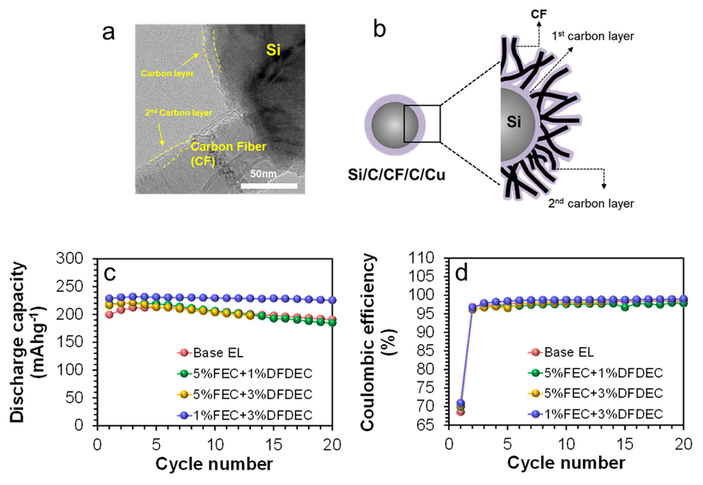
2.1. Material and electrochemical testing
Li1.13Mn0.463Ni0.203Co0.203O2 (LMNC) cathode was prepared by casting a slurry, consisting of 75 wt% active material that was synthesized by solid state method with (Mn0.463Ni0.203Co0.203)CO3 precursor [2,3] and LiOH at 900°C, 15 wt% carbon black (super P) and 10 wt % polyvinylidene fluoride binder (PVdF, Aldrich) in N-methyl-2-pyrrolidone (NMP, Aldrich), onto an aluminum foil to the loading level of ~3 mgcm−2, followed by vacuum-drying at 110°C for 12 hours. Si/C/CF/C-graphite anode active material was used as received from EG Inc., which included 15 wt% Si (EG, average size of 300 nm), and 85 wt % natural graphite (BTR). The surface of submicron Si particles was coated with the first layer of carbon, to which grown carbon fibers (CF) were anchored followed by coating the secondary carbon layer on it resulting in Si/C/CF/C. The copper (Cu) metal particles were added after the secondary coating of carbon layer resulting in Si/C/CF/Cu as shown in TEM image (Fig. 1a), whose amount is 0.9 wt% of the weight of Si/C/CF/C powder. This feature demonstrates a good electrical connectivity and conductivity among Si particles and between Si particles and graphite particles through coated carbon layers and carbon fibers of Si/C/CF/C/Cu. The anode of Si/C/CF/C/Cu-graphite was prepared by casting the slurry, which was composed of 75 wt% active material of Si/C/CF/C/Cu-graphite, 10 wt% carbon black (super P), and 15 wt% aqueous binder on a copper foil to the loading level of ~1.2 mgcm−2. The binder consists of sodium carboxymethyl cellulose (CMC, MW 250,000, Aldrich) and polyacrylic acid (PAA, MW 450,000, Aldrich) at the 1:1 weight ratio in deionized water. The coated anode was vacuum-dried at 110°C for 12 h. The optimized N/P ratio was 1.1. Lithium 2032 coin full-cells were assembled with Si/C/CF/C/Cu-graphite anode, LMNC cathode, and the based electrolyte (henceforth, based EL) of 1.0 M LiPF6/ethylene carbonate (EC): ethyl methyl carbonate (EMC) (3:7 volume ratio, Soulbrain) without and with fluorinated dual-additives of FEC (Sky E&M) and DFDEC (Sky E&M) at various fractions, and a separator (Celgard C210) in an argon-filled glove box (MOTek) with water and oxygen less than 1 ppm. The Si/C/CF/C/Cu-graphite||LMNC full-cells were tested between 2.0 and 4.7 V at the rate of 0.2C (50 mAg−1) at 25°C.
2.2. Surface and structural characterization
Particle morphology of Si/C/CF/C/Cu was examined using high-resolution transmission electron microscopy (HRTEM, JEOL JEM-2100F) at 200 kV. Surface characterization of pristine and cycled cathodes and anodes of full-cells was conducted using ex situ X-ray photoelectron spectroscopy (MultiLab 2000, Thermo) with an Al Kα X-ray source at 15 kV. The cycled cathodes and anodes were transferred from glove box to the XPS chamber without the exposure to air. High-resolution spectra were obtained at a power of 150W under a base pressure of 5 × 10⁻¹⁰ mbar with pass energy of 40 eV and spot size of 500 μm. To avoid the interfering effect of F Auger peak in Ni and Co 2p spectra of cycled cathodes and anodes in full-cells, those were measured using Mg Ka X-ray source at 15 kV with the irradiated spot size of 600 μm and the pass energy of 40 eV. The binding energy was calibrated based on the C 1s level at 284.5 eV. The curve-fitting on the Mn 2p3/2 peak was conducted with Gaussian (78%) and Lorentzian (22%) functions and full-width-half-maximum of 3.25 eV after having Shirley-type background correction, using XPSPEAK 4.1 program. Particle morphology changes of cathodes and anodes with cycling were monitored with field emission scanning electron microscopy (FE SEM, Hitachi S-4800) at 15 kV. Elemental mapping analysis was performed on anodes using SEM energy-dispersive spectroscopy (EDS) to determine the presence of deposited metal compounds.
Raman spectroscopic measurement was conducted on cycled cathodes and anodes in a closed cell to avoid atmospheric contamination, using a Raman microscope (Nanofinder 30, Tokyo Instrument Co.) with a He-Ne laser (632 nm). The power of laser beam was 3.0 mW and the diameter of laser beam at the sample was less than 1 μm in diameter.
3. Results & Discussion
3.1. Electrochemical cycling performance of 4.7 V full-cells
Si/C/CF/C/Cu-graphite||LMNC full-cells were assembled with base EL of 1M LiPF6/EC:EMC without and with FEC-DFDEC dual-additives and tested for their electrochemical charge-discharge cycle performance for a brief screening of amounts of additives between 2.0 and 4.7 V at C/5 at room temperature. The test results (Fig. 1c,d) determine that the use of 1 wt% FEC together with 3 wt% DFDEC provides the most improved performance, delivering initial Coulombic efficiency (ICE) of 71% and capacity retention of 97% at the 20th cycle, which is used for longer cycle tests. From the 3rd cycle, Coulombic efficiency (Fig. 1b) is maintained as higher than 99% with cycling. Note that the total amount of additives enables to be reduced to 4 wt%, compared to the use of 10 wt% or higher amount of FEC additive in Si-containing anode-based half-cells and full-cells in the literatures [9,17–22].
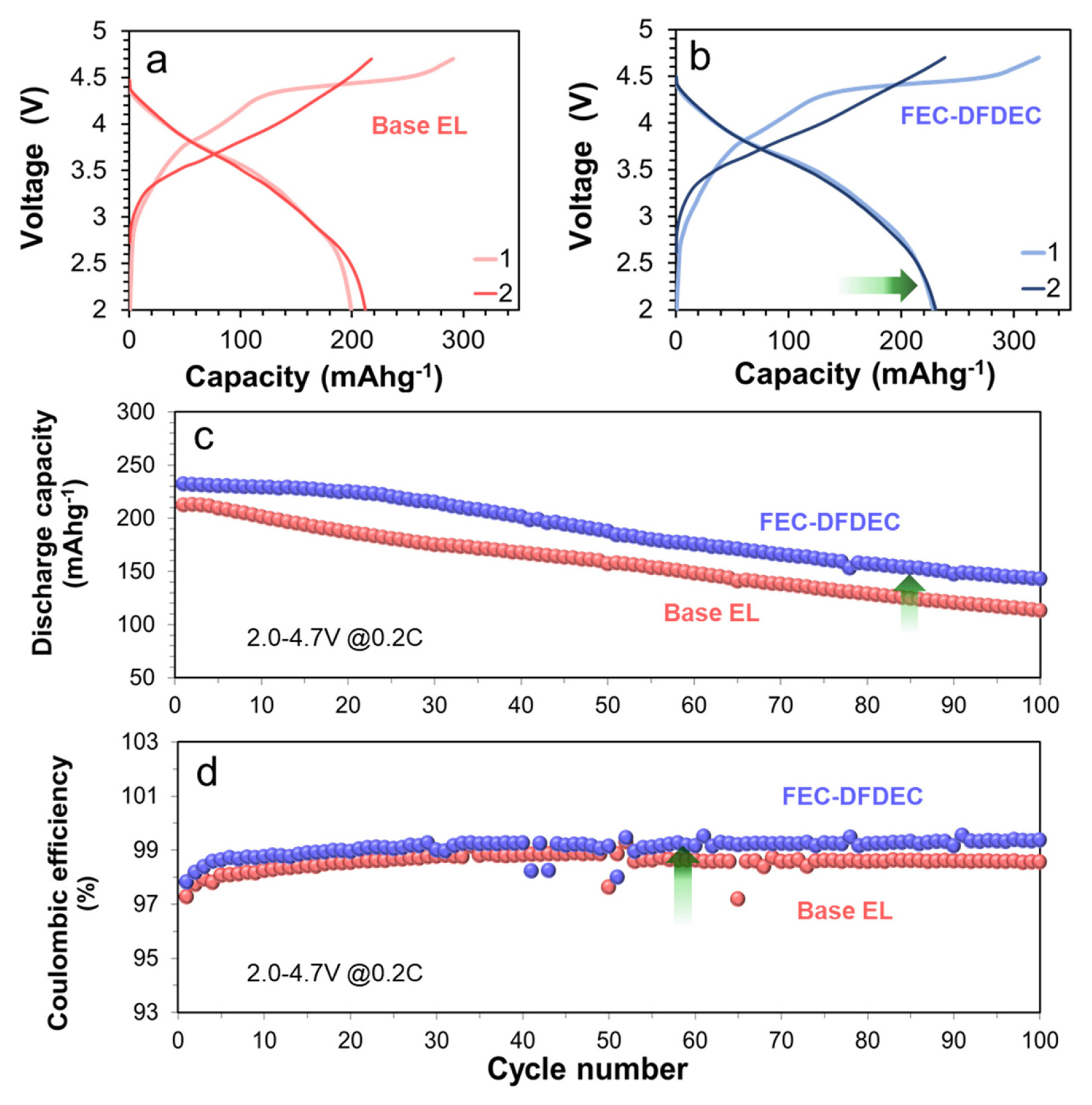
Fig. 2a,b compare the 1st and 2nd formation cycles of the full-cells in base EL without and with the dual-additives of 1 wt% FEC and 3 wt% DFDEC (henceforth, FEC-DFDEC). In base EL (Fig. 2a), full-cell exhibits the initial discharge capacity of just 199 mAhg−1 and the ICE of 68% due to anodic instability of the base EL and cathode-electrolyte interface under high charge cut-off voltage of 4.7 V. Upon the use of dual-additives (Fig. 2b), both initial discharge capacity and ICE increase to 228 mAhg−1 and 71%, respectively. Capacity retention at the 100th cycle (Fig. 2c) is also improved from 53% of base EL to 62% by the use of dual-additives. In particular, cyclic Coulombic efficiencies (Fig. 2d) are notably improved to higher than 99% during 100 cycles when using dual-additives. In order to understand what the effects and roles of FEC-DFDEC dual-additives on cathode and anode are in improving the performance of a high Si-containing and high-voltage LNMC-based full-cell, which will be the basis for the strategic design of further performance improvement, we have conducted surface and structure analyses of cathodes and anodes taken from the cycled full-cells.
3.2. Analysis of surface chemical state of cycled cathodes
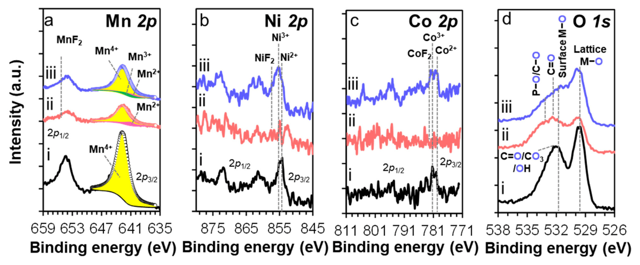
Fig. 3 compares the XPS spectra for the surface Mn, Ni, Co and O elements of pristine and cycled LMNC cathodes taken from full-cells. Surface Mn valance was determined by curve fitting on the Mn 2p3/2 peak of Mn spectra (Fig. 3a), employing multiple-splitting patterns derived for Mn2+, Mn3+, and Mn4+ at 641.0, 641.7, and 642.7 eV from the standard compounds of MnO, Mn2O3, and MnO2, respectively [1–3,23–25]. Fitting results (Table 1) indicate that surface Mn atom of pristine cathode (Fig. 3a–i) consists of 100% Mn4+-O. Cycling in base EL (Fig. 3a–ii) leads to the formation of 21% of Mn2+-O at the expense of Mn4 +-O, which is due to the electrochemical oxidation of electrolyte by electron transfer to cathode surface in the course of charge, followed by instant reduction of surface Mn4+-O to Mn3+-O or Mn2+-O [1–3,17,26]. The presence of soluble Mn2+-O into electrolyte implies a possible Mn2+O dissolution from LMNC cathode and simultaneous oxygen evolution from LMNC to maintain a charge neutrality. However, upon the use of FEC-DFDEC dual-additives (Fig. 3a–iii), the chemical state of surface Mn is relatively less altered from 100 % Mn4+-O of pristine to 82%, with the formation of 9% Mn2+-O and 9% Mn3+-O (Table 1). In particular, the presence of Mn3+-O, which is in the middle way of surface reduction from Mn4+-O toward Mn2+-O, is the direct indication of the suppression of Mn2+-O formation. Therefore, the suppression of metal-dissolution is achieved as well. Relatively stronger peak intensity of MnF2 at 655.7 eV in the Mn 2p (Fig. 3a–iii) and F 1s (Fig. S1) spectra when using dual-additives dictates the role of dual-additives as F-sources. The increased concentration of surface MnF2, instead of a whole Mn2+-O, might be the critical point to maintain better the surface chemical state of Mn and to suppress metal-dissolution event. In the Ni and Co 2p spectra, the surface of pristine shows the existence of mixed valent atoms as Ni3+-O/Ni2+-O (Fig. 3b–i) and Co3+-O/Co2+-O (Fig. 3c–i), respectively. While no longer the peaks of pristine are clearly seen after cycling in base EL (Fig. 3b–ii,3c–ii), the features are still present with FEC-DFDEC dual-additives (Fig. 3b–iii,3c–iii). This implies the formation of a relatively thinner SEI with dual-additives, consistent with slightly weakened spectral feature of other inorganic elements (Fig. S1). Clear features of NiF2 (Fig. 3b–iii) and CoF2 (Fig. 3c–iii) with dual-additives ensures the role of dual-additives as F-sources, similar to the case of Mn. The O 1s spectrum of pristine (Fig. 3d–i) exhibits peaks at 529.7 and 531.8 eV, attributed to the M-O of lattice oxygen and surface oxygen in the LMNC layered structure, respectively [1–3,27–29]. While relatively weakened peak intensity of lattice oxygen after cycling in base EL (Fig. 3d–ii) is related to the loss of oxygen and/or structural degradation, it remains well when using dual-additives (Fig. 3d–iii). Correlating to the FTIR observation (Fig. S2) of higher concentration of organic SEI species and XPS analysis of other inorganic elements-based species formed at cycled cathodes, the surface analysis provide the evidences that the use of dual-additives is effective in forming a surface protective SEI including metal fluorides and mixed organics and inorganics, mitigating metal-dissolution event and improving the surface structural stability of LMNC cathode.
3.3. Mitigating metal-dissolution and structural changes of cathode by the effects of dual-additives
SEM imaging exhibit that the particle morphology of LMNC primary particles remains unchanged from pristine (Fig. 4a) when using FEC-DFDEC dual-additives (Fig. 4c), i.e., prevention of particle cracking event, whereas remarkable particle size reduction after cycling with base EL (Fig. 4b). The metal dissolution event is developed and propagated from surface to bulk, causing crack formation and development with cycling. Such failure modes lead to a noticeable particle disintegration in base EL.
Metal-dissolution and oxygen evolution from LMNC cathode active material often causes a structural disordering. Raman spectroscopy was employed to monitor structural changes on LMNC cathode with cycling. Raman spectrum of pristine cathode (Fig. 4a′) shows two bands at 600 and 487 cm−1, attributed to the A1g and Eg modes, respectively, characteristic of the vibration of oxygen atoms to the ab-axis and the c-axis in the layered hexagonal structure (R3̄m) [1–3,28,30,31]. A tiny band at 433 cm−1 is assigned to Li–O bond of Li2MnO3 (C2/m) in monoclinic structure [1,2,32]. After cycling in base EL (Fig. 4b′), A1g band is blue-shifted to 632 cm−1 while being weakened. This is a typical signature of a structural change to spinel-like cubic [1–3,30]. However, upon the use of FEC-DFDEC dual-additives (Fig. 4c′), the original spectral feature remains, along with the presence of a weak shoulder near 615 cm−1 of spinel-like cubic phase [1–3]. FEC-DFDEC dual-additives is determined to be effective in not only stabilizing the surface structure but also stabilizing the particle morphology and bulk-part structure of LMNC cathode. Stabilizing the cathode-electrolyte interface using dual-additives leads to improved performance despite under 4.7 V high-voltage charge condition.
3.4. Mitigating metal-deposition and structural changes of anode by the effects of dual-additives
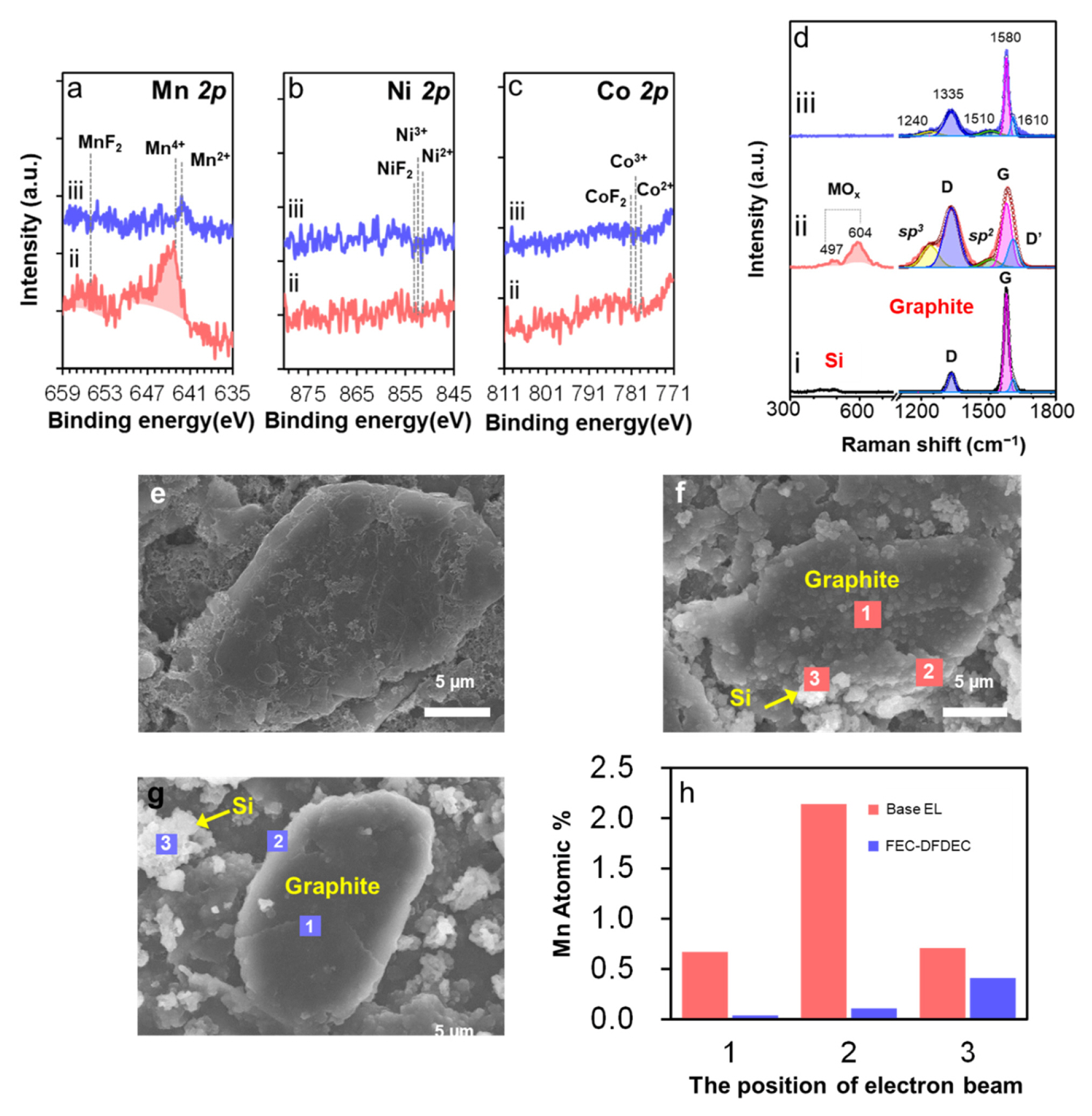
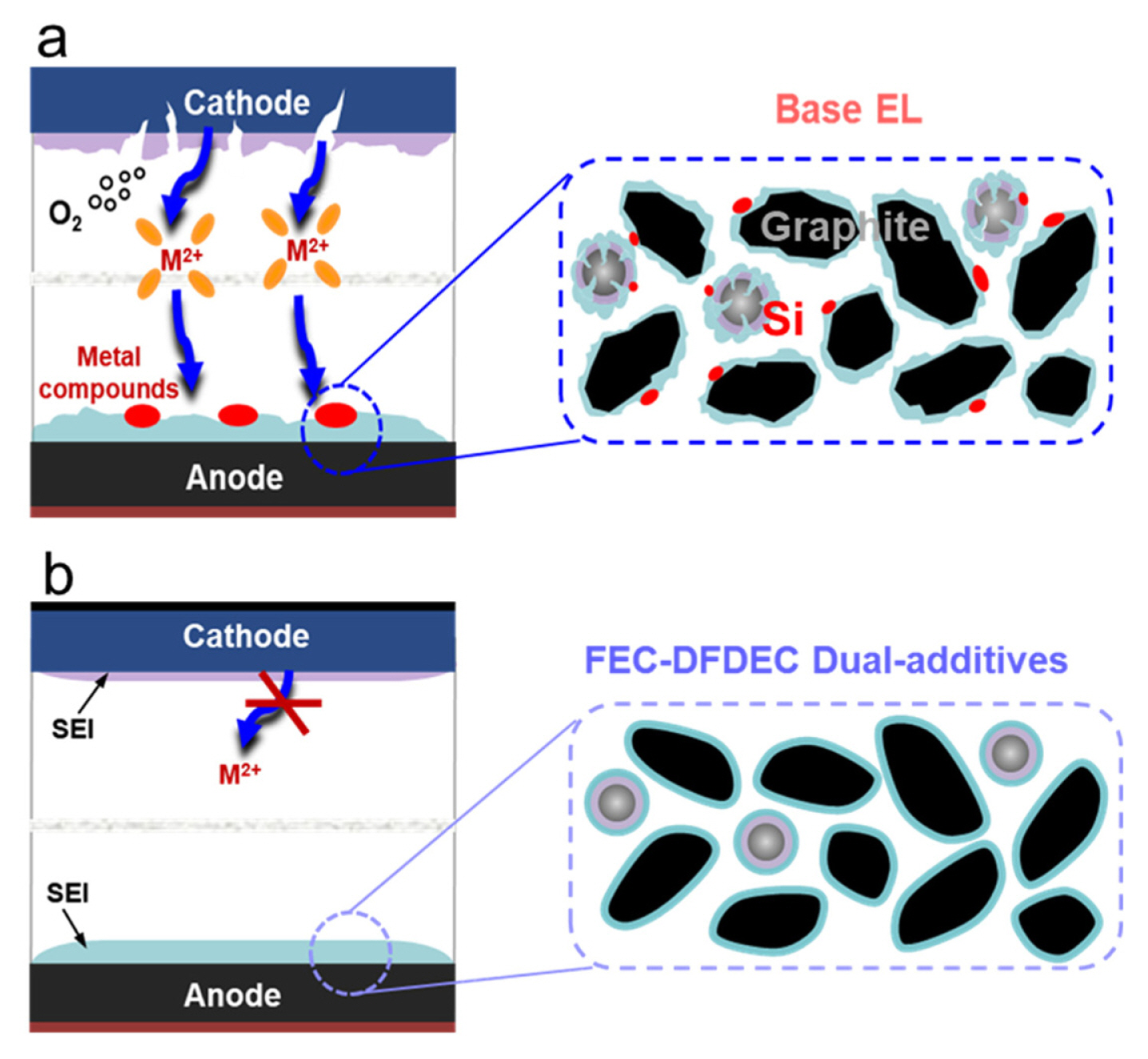
The dissolved species from LMNC cathode could be deposited at the surface of Si/C/CF/C/Cu-graphite anode during the full-cell operation. To investigate metal-deposition phenomenon, we conducted XPS analysis on the surface of cycled graphite anodes to check the presence of the metal elements, i.e., Mn, Ni and Co. The Mn 2p spectra of the cycled anode in base EL (Fig. 5a–ii) clearly show intense peaks of mixed valent oxides of Mn4+-O/Mn2+-O along with MnF2. In the Ni 2p and Co 2p spectra (Fig. 5b–ii,5c–ii), no clear feature of any surface species is detected. On the other hand, when using FEC-DFDEC dual-additives, weak peak of Mn2+-O is detected in the Mn spectrum (Fig. 5a–iii) but no feature in the Ni and Co 2p spectra (Fig. 5b–iii,5c–iii). Raman spectra of the cycled anodes support the presence of metal deposits. Raman spectrum of cycled anode in base EL (Fig. 5d–ii) exhibits new bands at 497 and 604 cm−1, attributed to transition metal oxides such as MnOx, NiOx [2,20]. These are the direct indication of metal-dissolution from LMNC cathode and metal-deposition at Si/C/CF/C/Cu-graphite anode during cycling of the full-cell, as illustrated in Fig. 6a. Metal-deposition event could be the origin of new side reactions with electrolyte, hindering the Li+ ion-transport to Si and graphite interlayers and finally deleteriously affecting cycling performance. However, the feature of metal deposits is absent in the Raman spectrum of cycled anode with FEC-DFDEC dual-additives (Fig. 5d–iii), correlated to XPS data (Fig. 5a–c), but the surface of cycled anode is covered with the SEI species. Relatively weaker peaks intensity of the surface elements of the SEI species upon the use of dual-additives (Fig. S3) indicates a thinner SEI layer than that of base EL. These are why SEM image of the cycled Si/C/CF/C/Cu-graphite anode (Fig. 5f) in base EL shows remarkably rougher surface than that of pristine (Fig. 5e), whereas the surface of cycled anode with dual-additives (Fig. 5g) remains smooth, having a full surface coverage of both Si and graphite particles with the SEI species. The metal deposition in base electrolyte was also detected using EDS elemental mapping (Fig. 5f and 5h), by focusing the electron beam on the points of edge and basal plane of a graphite platelet and on Si. It was confirmed that the deposits are of mainly Mn compounds, which particularly forms more at the edge than other points of graphite, as well as Si. Upon the use of dual-additives, just trace of Mn compound is observed at the surface of Si particles (Fig. 5g and 5h). The use of dual-additives plays a critical role in mitigating the metal-dissolution event from LMNC cathode as well as metal deposition at Si/C/PC/C/Cu-graphite anode by forming surface protective SEI layers at both cathode and anode (Fig. S1–2, S3–4), as illustrated in Fig. 6b.
Raman spectral analysis also provides useful information on any structural changes of of Si/C/CF/C/Cu-graphite anode with cycling. Raman spectrum of pristine anode (Fig. 5d–i) exhibits a prominent G-band (E2g) at 1580 cm−1 [33–35], relatively weaker D-band (A1g) at 1340 cm−1 and D′-band at 1610 cm−1 [36] that is associated with defects and disorder within graphite [36,37]. A tiny band of crystalline Si is present at 500 cm−1 [22,38]. Overall spectral feature of cycled anodes is very different from pristine; new bands near original D- and G-bands are observed but at different feature depending on the absence or presence of dual-additives, and no longer the band of crystalline Si is seen in common probably by being amorphous with cycling in both electrolytes. To determine the relative amount of different carbons and to understand how graphite structure evolves with cycling, we conducted curve fitting on the Raman spectra. Curve-fitting results are listed in Table 2. In general, the relative intensity ratio of D-band to G-band, i.e., R = ID/IG, is used as a measure for the degree of structural disorder of carbon material [36,37]. The obtained R value of pristine is 0.19. The higher departure from the R value of pristine, the higher structural disorder [36,37]. While the R value of cycled anode in base EL largely increases to 0.9 that is 474% increase from that of pristine (Table 2), the one with FEC-DFDEC dual-additives 0.31 corresponding to 163% increase. While the relative amount of D′-band in base EL also largely increases from that of pristine due to the formation of plenty of defects within graphite, its change is limited when using dual-additives (Table 2). In addition, Raman spectra of cycled anodes (Fig. 5d–ii,iii) exhibit two prominent bands at 1240 and 1510 cm−1, attributed to sp3- and sp2-hybrid carbons, respectively [39]. Those originate from organic SEI compounds and in part structurally disordered carbon in graphite. Band intensity and relative areal ratio (Asp3/Asp2) of the bands provides useful information on the concentration of surface species and chemical bond nature of newly formed organic SEI species, along with the degree of disorder of carbon-containing materials [36–39]. Changes in the Asp3/Asp2 ratio show similar tendency to those of D/G bands (Table 2); upon the use of dual-additives, much lower departure, 0.8, from pristine than the case in base EL. This implies the higher degree formation of various carbon-containing surface species and structural disorder at graphite anode in the presence of dual-additives, compared to the dominance of sp3-hybrid carbon at the anode surface in base EL. Overall, the data suggest that dual-additives induce to improve both structural and surface stability of graphite anode, in contrast to the occurrence of large structural disorder and intensive changes of surface state in base EL, all of which are correlated to cycling performance.
4. Conclusions
The use of fluorinated dual-additives is proved to be effective in stabilizing the SEI at LMNC cathode in a high-voltage Si/C/CF/C/Cu-graphite||LMNC full-cell, suppressing the formation of surface Mn2+-O at cathode, which is soluble to electrolyte. Thus the metal-dissolution event, consequent crack formation and particle cracking and structural change of cathode are all mitigated. Dual-additives also induces to form a good and thinner SEI at Si/C/CF/C/Cu-graphite anode, fully covering the surface of both Si and graphite particles and improving structural stability. On the contrary, cycling of the full-cell in base electrolyte only results in a metal-dissolution from cathode and deposition at anode, crack formation at cathode, thus structural degradation of both cathode and anode, resulting in inferior performance. Additive-derived interfacial stabilization based on a basic understanding of interfacial processes is believed to be required to improve the cycle life of high-voltage Li-ion batteries employing Li-rich cathode and Si-based anode.