1. Introduction
An electric double layer capacitor (EDLC) is an energy storage device that attains capacitance by forming an electric double layer of electrolyte ions on the porous surface of activated carbon. EDLCs are characterized by their excellent power and long-term reliability compared to Lithium-ion batteries (LIB) [1ŌĆō5]. The application fields of EDLCs are continuously expanding, from back-up power to powering communication devices and vehicles. With the rising diversity and advancement of industries, EDLCs are increasingly requiring high power to perform with improved long-term reliability [6ŌĆō8].
Researchers have extensively studied electrodes, electrolytes, and cell manufacturing processes to enhance the power properties and long-term reliability of EDLCs. In particular, studies on functional groups that can minimize the degradation reaction of activated carbon electrodes, porous structure control, and resistive component minimization are necessary [9ŌĆō12].
It is primarily because when preparing the activated carbon used as the active material for EDLCs, the electrode resistance increases and the degradation reaction of the cell accelerates because of the reaction of the functional groups inside the pores formed in the activation process with electrolytes and moisture. The degradation reaction in the activated carbon electrodes is primarily influenced by the adsorbed water and functional groups on the activated carbon porous surface [13ŌĆō15]. Since the adsorbed water has hydrogen bonds in the functional groups, it is highly stable and difficult to remove. Therefore, the components react with the electrolytes or binder components at high temperature or high voltage to generate H2, CO, and CO2 gases, or form a polymer layer on the activated carbon pores or surface to reduce the electric double layer capacitance [16ŌĆō18]. Moreover, fluorine generated in the degradation process corrodes the surface of the current collector, which further accelerates degradation [19]. For activated carbon, several studies are underway to improve the porous structure and modify the surface by N-doping, whereas for current collectors, efforts to identify and suppress the causes of surface corrosion are relatively insufficient.
Etched aluminum is primarily used as the current collector of activated carbon electrodes for EDLCs. In etched aluminum, etch pits and a hydrous oxide layer on the surface are formed during the etching process. The etch pits are expected to enhance the binding force with the electrodes, enabling the hydrous oxide layer to act as a stable passivation layer [20,21]. However, it has been reported that during the degradation process, corrosion reactions of AlF3 proceed on the etched aluminum surface by F generated from side reactions of the electrolyte and hydrolysis of BF4ŌłÆ ions, or HF gas generated by H2 and electrolyte reactions [9,19].
Numerous studies have aimed at reducing the interface resistance and preventing surface corrosion reactions; specifically, to improve degradation reactions occurring at the interface between the etched aluminum current collector and the electrodes [22,23], the etched aluminum surface was coated with carbon paste prepared by dispersing carbon, such as carbon black, graphene, and graphite, to form a carbon conductive layer [24ŌĆō29]. However, when preparing the carbon paste, carbon blackŌĆöwhich has sub-micron sizesŌĆötends to aggregate during the dispersion process, and when applying a 1 ╬╝m thick gravure coating, it is easy to increase the resistance of the activated carbon electrodes because of the increased number of contacts between the carbon black powders. As for graphene, it is difficult to disperse or exclude the influence of functional groups introduced in its chemical processes, which increases the likelihood of degradation [30].
In this study, carbon fiber was used to coat the surface of an etched aluminum current collector and form a carbon fiber layer to improve the power and long-term reliability of activated carbon electrodes and the degradation of electrodes and current collectors. The vapor-grown carbon fiber has high electrical conductivity and low surface area simultaneously. Therefore, the dispersion stability of carbon fiber is higher than that of carbon nanotubes. Subsequently, its electric and electrochemical properties were examined. A mixture of a binder and planetary-milled carbon fiber was uniformly dispersed, and a carbon fiber layer was coated on the surface of etched aluminum. The power and long-term reliability of the activated carbon electrodes formed on the carbon fiber layer were analyzed via a floating test, which assessed the capacitance retention while maintaining the internal resistance and a constant voltage of 3.3 V for 500 h.
2. Experimental
2.1 Preparation of Carbon Fiber layer
Vapor-grown carbon fiber (VGCF-H, SHOWA DENKO KK, JAPAN Co.) was used to prepare a carbon fiber (CF) paste to form a CF layer on the etched aluminum surface. To uniformly disperse and coat the CF on the surface, the length of CF was adjusted by applying a planetary mill process. The weight ratio of CF and zirconia ball was adjusted to be 15, and the planetary mill process was conducted at 30, 90, and 150 min at 150 rpm.
CF milled for 150 min was dispersed in a carboxymethyl cellulose (CMC, WS-C, Dai-ich) binder to prepare the CF paste. To disperse the CF, isopropanol (IPA, Sigma-Aldrich) was added, and the mixture was sonicated for 10 min, following which CMC binder and DI water were added and homogenized. Upon fixing the CMC at 4.3 wt.%, CF pastes were prepared with CF contents of 1, 3, 5, and 7 wt.%.
A doctor blade was used to coat the CF paste on the surface of the etched aluminum current collector (20CB, Ōēź99.7%, 20 ╬╝m, JCC Co. LTD.), and after coating, it was vacuum-dried in an oven at 100┬░C for 6 h.
2.2 Fabrication of EDLCs
Activated carbon (YP50F, 1700 m2/g, Kuraray, JAPAN Co.) was used as the active material of the activated carbon electrodes. Carbon black was used for the conductive material, and CMC and SBR were used for the binder. Regarding the electrode composition, Activated carbon : Super P Black : CMC : SBR was mixed at a ratio of 85 : 8 : 4 : 3 (wt.%) in preparing the slurry. The slurry was coated on the etched aluminum or etched aluminum current collector coated with the CF layer and then vacuum-dried at 120┬░C for 12 h. The dried activated carbon electrodes were rolled using a roll-press device until their thickness was 80 ╬╝m. To fabricate pouch-type EDLC cells, the electrodes were slit to 2.5├Ś2.5 cm2, and a separator was placed in the middle and assembled to form the cells. Subsequently, 1.5 M SBPBF4 in AN (acetonitrile) was used for the electrolyte. Of the pouch-type EDLC cells, the cell using a current collector without CF coated on the etched aluminum was the reference, and the cells using a current collector with CF paste coated on the etched aluminum surface were named as follows according to the CF content (wt.%): CF-1 layer for CF 1 wt.%, CF-3 layer for CF 3 wt.%, CF-5 layer for CF 5 wt.%, and CF-7 layer for CF 7 wt.%.
2.3 Characterizations and Electrochemical measurements
The particle sizes of the CF and planetary-milled CF were analyzed using a particle size analyzer (PSA, Malvern Mastersizer 2000E). A field emission scanning electron microscope (FE-SEM, Hitachi, S-4800) was employed to analyze the geometry and structure of the CF. The CF layer formed on the current collector surface, and the current collector/electrode was coated with the CF layer. For the cross-sectional analysis of the electrode, the cross section was processed at a speed of 500 ╬╝m/h using a cryo cross section polisher (CCP, JEOL, IB-19520CCP), after which an element mapping analysis was conducted using FE-SEM and energy dispersive spectroscopy (EDS, Hitachi, EMAX). An electrode resistance meter (RM2610, HIOKI), which is a measurement device using 46 probes, was used to measure the active materials resistance (╬®┬Ęcm) of the electrode and interface resistance (╬®┬Ęcm2) between the composite layer and current collector.
The charge-discharge and degradation tests of the EDLC cells were evaluated by constant current using a charge-discharge tester (Maccor, 4300K series). The voltage range is 0~3.0 V, the current density is measured in the range of 2~500 mA per electrode area, and the capacitance (F) was obtained with Equation (1) below using the discharge time (Δt), discharge current (i), and change in voltage (ΔV) [31].
To analyze the degradation properties of the EDLC cells, we conducted a floating test on the change in capacitance at a constant voltage of 3.3 V. The floating test involves a pattern of charging to 3.3 V at a constant current of 2 mA per electrode area, maintaining the constant voltage for 10 h, discharging to 0 V, and then charging and discharging in the voltage range of 0~2.7 V. The process was repeated 50 times to test the change in capacitance retention (%) for a total constant voltage retention time of 500 h. Once a constant voltage range was maintained for 10 h, in the charge-discharge test of 0~2.7 V, the discharge capacitance was measured and the corresponding capacitance was obtained, and each constant voltage retention time was set to the floating time to measure the change in capacitance.
To examine the porous structure of the electrodes that completed the floating test, the cell was disassembled and the electrodes were immersed in acetonitrile (AN) and DI water, ultrasonically cleaned, and dried in a vacuum oven at 150┬░C. Following that, the samples were collected in a powder state and examined via BrunauerŌĆōEmmettŌĆōTeller (BET, Microtrac-BEL, BELSORP-Max) analysis. The specific surface area (SSA) of the raw activated carbon material and carbon electrodes before and after the floating test was calculated using the BET technique, and the pore volume was calculated using the t-plot technique.
3. Results and Discussion
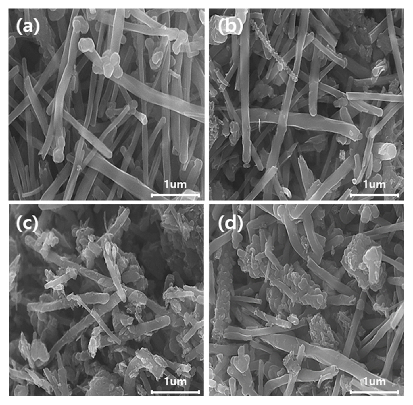
Fig. 1 displays the SEM images of the CF and planetary-milled CF. In the figure, the CF length decreased according to the milling time, and partial aggregation by the pulverized CFs can be observed. Compared to the average particle size (d90) of the CF obtained in the particle size analysis (PSA) of 11 ╬╝m, the CFs milled for 30 min, 90 min, and 150 min exhibited values of 7, 3, and 2 ╬╝m, respectively. While the CF length decreased according to the milling time, the aggregation of some particles was observed from approximately 90 min and longer. Subsequently, the CF with excellent dispersibility milled for 150 min was employed to prepare the CF layer. The Et. Al substrate has significant high surface roughness with numerous holes and corrugated morphologies. The surface roughness could be increased with increasing CF length. Although the density of aggregated CF revealed higher than that of CF without milling process, the size of aggregated CF (~1 ╬╝m) is lower than that the pristine CF (~11 ╬╝m) as shown in Fig. 1. Long carbon fibers can rather cause agglomeration on the substrate. Therefore, the surface morphology could be significantly affected by the electrical conductivity on the CF coated Et. Al electrode as shown in Fig. 2.
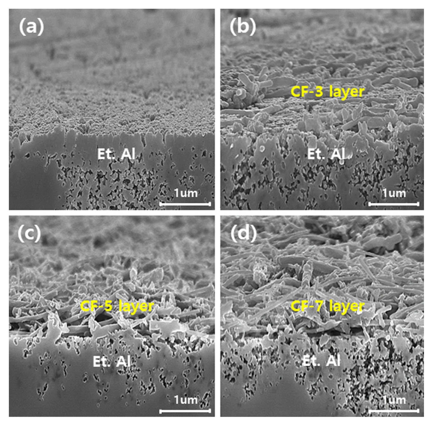
Fig. 2 illustrates the cross-sectional SEM images of the CF-x (x = 3, 5 and 7) layers coated on the etched aluminum surface using planetary-milled CF. The CF-3 layer formed a single layer of CF on the etched aluminum surface, whereas several overlapping layers were observed from the CF-5 layer.
The carbon coverage (%) was measured from the CF layer thickness and carbon mapping via EDS analysis, which is shown in Fig. 3. In the figure, for the CF-3 layer with a CF content (wt.%) of 3 wt.%, as the CF coverage increases, CF becomes uniformly dispersed on the current collector surface and coated in a single layer, whereas for the CF-5 layer with a CF content (wt.%) of 5 wt.%, several overlapping layers are thickly coated as the CF coverage increases.
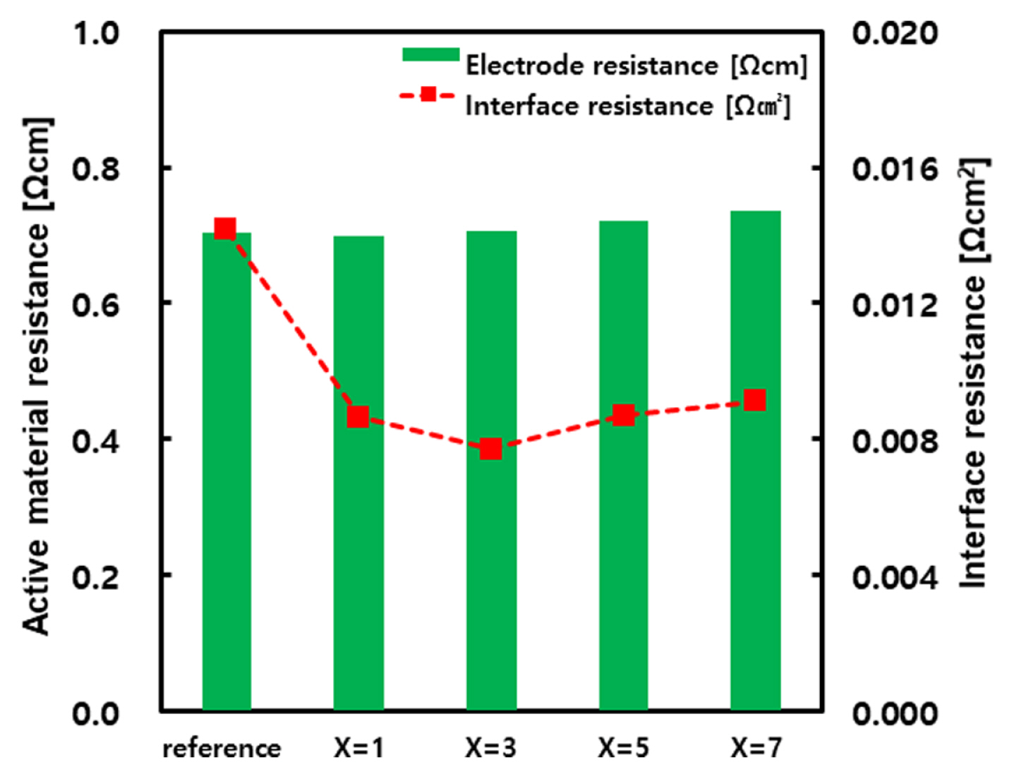
Fig. 4 presents the active material resistance (╬®cm) and interface resistance (╬®┬Ęcm2) measurements of the reference electrode and electrodes applied with the CF-x layer (x=1, 3, 5, 7). The active materials resistance exhibited similar measurements regardless of CF layer coating, whereas the interface resistance decreased in the electrodes coated with a CF layer compared to the reference electrode. As evidenced by the change in resistance according to CF content, the lowest interface resistance was observed in the CF-3 layer, which tended to slightly increase as the CF content increased. Generally, etched pits on the etched aluminum surface enlarge the contact area with the electrodes by creating curves in the surface geometry. However, the activated carbon and conductive materials contained in the electrodes are almost spherically shaped, and form point-contact conductive passages when in contact with the etched aluminum. As long as the carbon powders have a spherical shape, increasing the number of point contacts will inevitably have a limit, even if the electrode density in the entire electrode area is high [30].
Therefore, the CF layer likely reduces the interface resistance of the electrodes by forming a linear contact between the carbon powders of the electrodes and the etched aluminum, thus maintaining a higher contact area than point contacts and increasing the electric network. The lowest interface resistance was measured in the CF-3 layer because the CF is uniformly coated as a single layer on the etched aluminum surface. However, if the current collector surface is coated with several thickly overlapping layers, as in the CF-5 and CF-7 layers, then the interfacial diffusion properties decrease, and the interface resistance increases.
Fig. 5 illustrates the voltage discharge behavior of the EDLC cells using the reference electrode and electrodes coated with CF-x (x=1, 3, 5, 7) layers. Fig. 5 shows the discharge behavior in the voltage range from 3.0 V with current densities of 2 and 500mA/cm2, respectively. Based on the linear voltage behavior, the electrodes exhibit typical electric double layer behavior. The specific capacitance obtained at a current density of 2 mA/cm2 was approximately 30 F/g, whereas that obtained at a current density of 500 mA/cm2 decreased while varying according to the CF content. The specific capacitance obtained at a current density of 500 mA/cm2 was the highest in the EDLC with the CF-3 layer at 25 F/g. The insets in the figure show a magnification of the IR-drop range that appears during discharge following the CV section. The IR-drop increased as the current density increased.
Fig. 6 illustrates the equivalent series resistances (ESR) obtained from these IR-drops. ESR is the value obtained by dividing the change in voltage from the starting point of IR-drop to the point where the vertical line intersects with the capacitance slope by the applied current, and indicates the internal resistance of the cell. The internal resistance was lowest in the CF-3 layer regardless of the current density, which then increased as the CF content increased. The results are consistent with the changes in interface resistance depicted in Fig. 4, indicating that the interface resistance directly influences the internal resistance of the cell. The interface resistances related to electrodes include the electrode resistance (Relectrode), interface resistance (Rcontact), and current collector resistance (Ralumium); since the resistances are in series, a change in interface resistance directly impacts the electrode resistance. It has been reported that the interface resistance component that influences the internal resistance of the cell is approximately 30%, exerting a large effect on the total internal resistance [32].
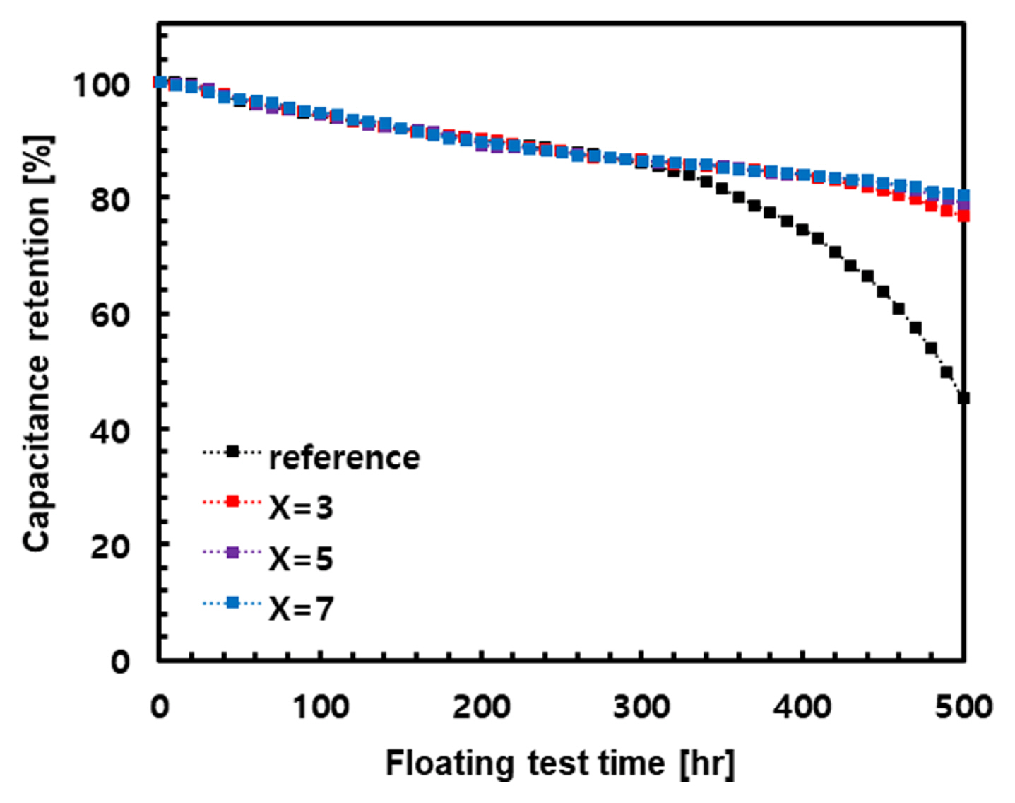
Fig. 7 illustrates the capacitance retention according to the floating test of the reference electrode and electrodes with CF-x (x=3, 5, and 7) layers. The reference electrode exhibited a sharp decline in capacitance retention from approximately 320 h, and then exhibited a value of 45% at 500 h. However, electrodes with current collectors applying a CF-x (x = 3, 5, and 7) layer yielded improved capacitance retention. The capacitance retention improved as the CF content increased, reaching a maximum of 80% at 500 h in the CF-7 layer.
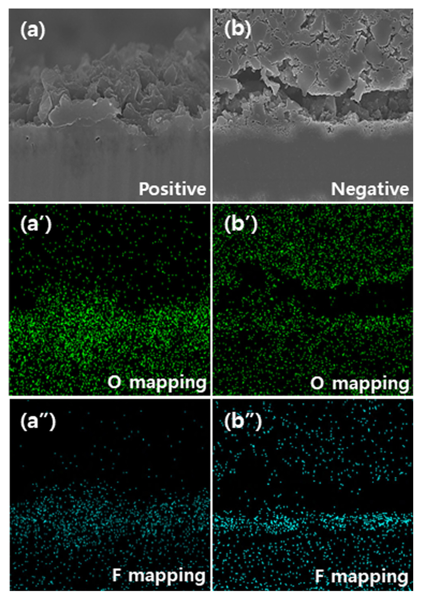
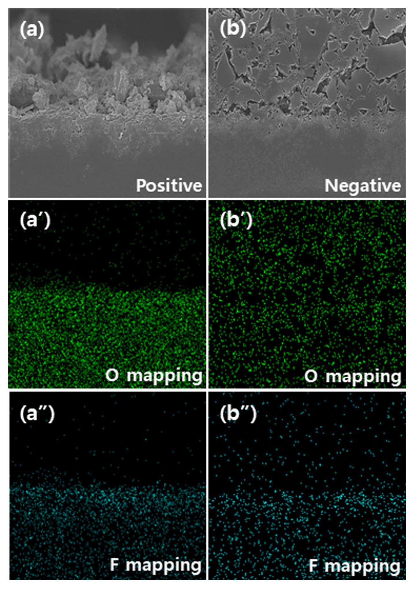
To investigate the influence of the CF layer on degradation behavior, we captured cross-sectional photos of the anode and cathode after 500-hour floating tests of the reference electrode and electrode with the CF-3 layer, which are displayed in Figs. 8 and 9. (a) and (b) depict the anode and cathode, (aŌĆ▓) and (bŌĆ▓) illustrate the O mapping results of the anode and cathode, and (aŌĆ│) and (bŌĆ│) present the F mapping results of the anode and cathode, respectively. Although some of the carbon powders in the anode remained on the etched aluminum surface, most of the electrode components were not observed. This is likely because the carbon powders are separated from the current collector during cross-sectional processing because of the bonds between the carbon powders, which are weakened at the interface between the electrodes and current collector. Generally, if an EDLC cell is left at a high voltage of 2.7 V or more for a long period of time, the electrodes inside the cell degrade. Regarding the degradation mechanisms, studies report that for anodes, it is primarily caused by the oxidative decomposition of oxidative surface functional groups, such as carboxyl, phenol, and ketone in the activated carbon pores. For cathodes, it is caused by Hoffman elimination reactions between the adsorbed water and cation ions in the activated carbon pores and electrolyte hydrolysis. These reactions are primarily evidenced by the generation of H2, CO, and CO2 gases at high voltages and the formation of side-reactants, such as film-like deposited materials and fluorinated polymeric films, on the activated carbon surface [13,18]. Additionally, after analyzing the SSA of the activated carbon electrodes subject to the degradation test, the extent of degradation can be evaluated based on the results on the blockage of pores and reduction of surface area [14].
Table 1 lists the SSA and pore volume ratios of the pores of the activated carbon, carbon powders separated from the reference electrode, and carbon powders separated from the reference electrode subject to the floating test and electrodes with the CF-3 layer. The SSA of the carbon powders separated from the reference electrode is slightly smaller than that of activated carbon because they contain conductive materials with a small SSA in addition to activated carbon. Following the completion of the floating test, the SSA of the anode carbon powders exhibited similar values of 758 and 774 m2/g regardless of the presence of a CF layer. These values are approximately half that of the reference electrode, and the cause of degradation can be found in the reduced micropore fraction of the activated carbon. The micropores have relatively many acidic functional groups involved in oxidative decomposition, and it can be inferred that the side reactants produced by oxidative decomposition block the many micropores and suppress the formation of the electric double layer. Moreover, regarding the weak mechanical strength of the anode, it can be inferred that the rapid release of gas and adsorbed water generated during oxidative decomposition partially destroy the structure of activated carbon, or the side reactants weaken the bonds between carbon powders.
Meanwhile, following the floating test, the SSAs of the cathode carbon powders were higher than those of the anode carbon powders, and the change in fraction between micropores and mesopores was small. As reported in the literature, it is because the side reactants produced by hydrolysis cover the entire cathode rather than the pores. Consequently, degradation inside the activated carbon is relatively small [18].
In Figs. 8 and 9, a definitive difference according to the presence of a CF layer is observed in the cathode. In the reference electrode, it is separated from the etched aluminum surface, whereas the electrode with the CF-3 layer maintains the electrode geometry. In the O and F mapping results, it is difficult to find distinct differences in the distribution of O. Conversely, for the separated cathode, F components are strongly detected on the etched aluminum surface. This suggests that F generated from hydrolysis of BF4ŌłÆ or HF gas reacted with aluminum to form AlF3 on the surface. The AlF3 corrodes the etched aluminum surface, which reduces the binding force between the negative electrodes and etched aluminum, causing the electrodes to separate from the etched aluminum [9].
Thus, the accelerated degradation of the reference electrode from 330 h in Fig. 7 is likely because, in addition to the degradation of existing activated carbons, corrosion between Al-F of the etched aluminum spreads across the surface over time.
Meanwhile, in the cathode using the CF-3 layer, an F distribution suggesting the formation of AlF3 is not observed. As mentioned above, compared to point contact, a linear contact using CF has a larger contact area and excellent electrical conductivity. In point contact, the point contact area is gradually reduced as corrosion spreads. As the point contact area decreases, the rise in power density locally concentrated in the point contacts and the resulting generation of resistance heat accelerates the corrosion rate. However, for the cathode using the CF-3 layer, no accelerated degradation was observed in the floating time range. It can be attributed to the increased contact area by CF, which suppresses corrosion in the long term, and does not provide additional causes of degradation other than degradation of the cathode activated carbons. Reflecting this, in Table 1, the cathode carbon powders with a CF-3 layer exhibited the smallest decrease in SSA compared to the carbon powders of the reference electrode.
Based on these results, as the CF formed a single layer with high coverage, the interface resistance and internal resistance decreased in the electrodes and EDLC cells with the CF layer, respectively. Additionally, as the CF content increased, the EDLC cells with the CF layer exhibited an excellent degradation suppression effect in the 3.3 V floating test. This is most likely because, the electrical conductivity improves and corrosion between Al-F on the etched aluminum surface of the cathode is suppressed following an increase in the contact area by CF.
4. Conclusions
To improve the degradation properties of etched aluminum current collectors applying EDLC, a CF layer was coated on the surface and the electrochemical properties were investigated. To improve dispersibility, a planetary mill process was applied to prepare CF with a uniform particle size. The CF milled for 150 min was mixed with a binder to prepare a CF paste, which was then coated on the surface of etched aluminum current collectors. The CF pastes were prepared according to the carbon fiber content (1, 3, 5, and 7 wt.%). When CF paste with CF 3 wt.% was coated on the etched aluminum current collector surface, a single CF layer with a thickness of approximately 1 ╬╝m was formed. However, when adding larger amounts of CF, several overlapping CF layers formed on the current collector surface, and the coating thickness also increased.
The interface resistance of the activated carbon electrodes and internal resistance of the EDLC cells were lowest when the CF weight ratio was 3 wt.%, and they increased with weight ratios of 5 wt.% or more. Meanwhile, according to the floating test results at 3.3 V, the EDLC cells with a CF layer exhibited substantially suppressed degradation compared to the EDLC cells without a CF layer. Regarding the changes in capacitance retention according to CF weight, as the CF weight ratio increased, the capacitance retention of the EDLC cell improved, up to 80% at a CF weight ratio of 7 wt.%.
The enhanced electrochemical properties can be explained by the changes in thickness of the CF layers and coverage according to the CF weight. When the CF forms a single layer with increased coverage on the etched aluminum surface, the linear contact area improves; thereby enhancing electrical conductivity. However, when the CF is coated in several overlapping layers and the thickness increases, the interfacial diffusion properties between the current collector and electrode are reduced, which increases the interface resistance.
Meanwhile, the results indicated that in addition to the degradation of the activated carbons, the degradation of the EDLC cells was also influenced by Al-F corrosion on the etched aluminum surface of the cathode. The CF layer protected the etched aluminum surface and suppress corrosion, and as the thickness of the CF layer increased, the coverage also increased and the degradation suppression effect improved.