1. Introduction
With environmental issues receiving more and more attention on a worldwide scale in recent years, renewable energy has emerged as a key strategy for accelerating energy transformation and lowering carbon emissions. The process of producing hydrogen electrolysis is a significant means of converting renewable energy sources into clean, efficient energy that has gained widespread attention in the context of renewable energy. In order to produce high-purity hydrogen, the basic idea of electrolytic hydrogen production technology is to divide water using electricity into hydrogen and oxygen. With its environmental protection, high efficiency, and sustainability features over traditional fossil fuel hydrogen production methods, electrolytic hydrogen production technology has steadily grown in importance as a way of achieving the clean energy transition. At now, the energy efficiency of electrolytic hydrogen production is quite low, and the efficiency of converting electric energy into hydrogen needs to be enhanced. To increase the stability and efficiency of electrolytic hydrogen production technology, it is imperative to design stable and effective hydrogen evolution catalysts [1]. The most popular catalysts for hydrogen evolution at the moment are Pt-based catalysts made of precious metals, yet their large-scale application is restricted by their cost and reserve availability [2]. As a result, non-precious metal catalysts with high availability and low cost have become a focus of research [3].
Due to its inexpensive cost, plentiful reserves, and potent electrocatalytic activity, transition metal nickel was frequently utilized as an electrode material in hydrogen evolution reactions (HER) [4]. Nonetheless, Ni consistently shown a high capacity for hydrogen adsorption in HER, which was detrimental to the hydrogen desorption reaction [5]. The current approach that was frequently utilized to increase the intrinsic activity of catalysts based on nickel was element doping, which modified the electron distribution to modify the adsorption energy of reaction intermediates [6]. Among them, nickel-based sulfides (such as NiS, Ni3S2) were favored because of their high conductivity and unique electronic structure [7ŌĆō9]. However, the catalytic activity of nickel-based sulfides was limited by their high kinetic barrier [10]. As a result, researchers continued to doping metal elements on the basis of nickel-based sulfides. Mo is a popular N-type dopant that can enhance the stability, electrical conductivity, and free electron concentration of electrode materials [11]. Although it was evident that doping with foreign atoms may boost the electrocatalytic activity, it remained challenging to obtain acceptable outcomes [12ŌĆō14].
To enhance its catalytic efficiency, electrode materials can also be morphologically modified in addition to element doping [15,16]. By increasing the active site and enhancing intrinsic activity, the unique structure can jointly optimize the electrocatalytic performance [17,18]. Li et al. prepared a hollow structure Mo-NiSx/NF for HER by solvothermal method, the overpotential and Tafel slope were 144 mV and 62.1 mV decŌłÆ1, respectively [19]. Li et al. created three-dimensional Mo-doped Ni3S2 mesoporous nanostructures that have outstanding energy storage and conversion capabilities and may be applied to overall water splitting [20]. Venkatesh et al. prepared Ni-MoS2 electrocatalyst with nanosheet structure, and the overpotential and Tafel slope for HER were 302 mV and 66.27 mV decŌłÆ1, respectively [21]. Despite the development of Mo-doped nickel-based sulfide catalysts with a variety of morphologies, comparative studies comparing the HER performance of the same catalyst with different shapes were lacking. It is very beneficial to determine the morphology of nickel-based sulfide catalyst which is most suitable for Mo doping.
Currently, one popular technique for creating electrocatalysts is the solvothermal method. By adjusting the solutionŌĆÖs composition, temperature, pH, precipitator, surfactant, and other preparation-related parameters, the morphology can be changed. The catalystŌĆÖs morphology may be more easily and effectively adjusted by the surface structure regulator, which can even achieve customisation of the exposed crystal surface and morphology [22]. FŌłÆ is a strong electronegativity that can influence grain formation, which is why shape tailoring and crystal engineering frequently use FŌłÆ as a surface structure regulator [23,24]. Xu et al. prepared CoP with different morphologies (nanowires, nanorods, and nanoblocks) by changing the concentration of NH4F in the solvothermal process [25]. Wang et al. prepared layered microspherical SnO2 by adding NH4F [26]. Chen et al. also used NH4F to change the morphology of NiCo2O4 and applied it to supercapacitors [27]. It follows that NH4F, as a surface structure regulator, can similarly modify the morphology of Mo-doped nickel-based sulfide catalysts in an efficient manner. This hasnŌĆÖt been reported, though.
Herein, Mo-doped nickel-based sulfide catalysts were modified in morphology using the solvothermal approach by adding NH4F of different grades. The effects of NH4F on the structure, morphology, specific surface area and electron distribution of Mo doped nickel-based sulfide catalysts were investigated. The impact of morphologies on catalyst activity was then ascertained by examining the stability and activity of catalysts with various morphologies. The studyŌĆÖs findings will serve as a guide for the advancement of catalyst morphology in the field of producing hydrogen through water electrolysis.
2. Experimental
2.1 Chemical Reactants
NiSO4┬Ę6H2O (AR), (NH4)2MoO4 (AR), NH4F (AR), Na2S┬Ę9H2O (AR), KOH (AR), and Pt/C (10 wt.% Pt) were from Aladdin Reagent (Shanghai) Co., LTD. Nafion (5 wt.%) was from Shanghai Macklin Biochemical Technology Co., Ltd. The above reagents were not purified before application.
2.2 Preparation of Mo-NiS-Fx
NF (2├Ś3 cm) was first ultrasonically cleaned for 15 min using ethanol, 1 M hydrochloric acid, and deionized water, and then vertically placed in a 150 mL Teflon autoclave. Subsequently, 1.38 g of NiSO4┬Ę6H2O, 0.82 g of (NH4)2MoO4, and 1.8 g of NH4F were dissolved in 100 mL deionized water, then placed in the reactor and maintained at 150┬░C for a duration of 12 h. NF was rinsed three times with deionized water following the reaction. The electrocatalyst precursor had grown on NF by this stage. The precursor was subsequently sulfured. After dissolving 1 g of Na2S┬Ę9H2O in 50 mL of deionized water, the mixture was added to a Teflon autoclave and maintained at 60┬░C for 6 h. Following the reaction, NF was dried under vacuum for 12 h at 60┬░C after being rinsed three times with deionized water. The electrode that was produced was identified as Mo-NiS-Fx, with x standing for the weight of NH4F.
2.3 Preparation of Pt/C@NF
As a control catalyst, 5 mg of Pt/C was dispersed into the solution of 20 ╬╝L of 5 wt.% Nafion solution and 300 ╬╝L of water/ethanol. Then the mixture solution was impregnated on NF and dried under vacuum at 60┬░C for 6 h. The obtained Pt/C@NF has a loading capacity of 2.5 mg cmŌłÆ2.
2.4 Characterizations
X-ray diffraction (XRD) was carried out on an XŌĆÖPert PRO PANanalytical instrument (Bragg-Brentano geometry with fixed divergence slits, position sensitive detector, continuous mode, room temperature, Cu K╬▒ radiation). Scanning electron microscopy (SEM) was carried out on a Hitachi SU-70. Transmission electron microscopy (TEM) and energy-dispersive X-ray spectroscopy (EDS) elemental mapping was performed on a FEI Tecnai G2 F30 S-Twin and OXFORD MAX-80 energy-dispersive X-ray detector (EDX). X-ray photoelectron spectroscopy (XPS) was measured by Kratos spectrometer (AXIS Ultra DLD) using the standard monochromatic Al K╬▒ line (h╬Į = 1486.6 eV) as the excitation source. Nitrogen absorption/desorption isotherms are measured on a Micromeritics ASAP2460 instrument and after the samples are degassed about 4 h at 100┬░C and the specific surface areas are calculated by the Brunauer-Emmett-Teller (BET) method. The content of Ni and Mo in the samples were detected by inductively coupled plasma-atomic emission spectroscopy (ICP-AES) on a Perkin-Elmer Optima 7300 DV spectrometer. The elemental analyzer model is Vario ELIII.
2.5 Electrochemical Measurements
The electrocatalytic performance was tested with Parstat4000+ electrochemical workstation. A three-electrode system was adopted, with Mo-NiS-Fx as the working electrode, graphite rod as the counter electrode, Hg/HgO electrode as the reference electrode, and 1 M KOH solution as electrolyte. Before the test, CV activation was performed in the activation interval of (ŌłÆ1.85)ŌĆō(ŌłÆ0.85) V (vs Hg/HgO) and the scan rate was 0.1 V sŌłÆ1 until the curve did not change. Then, linear sweep voltammetry (LSV) was used to test HER performance of the electrocatalyst in the range of (ŌłÆ0.85)ŌĆō(ŌłÆ1.85) V (vs Hg/HgO) at a scanning rate of 5 mV sŌłÆ1. Electrochemical impedance spectroscopy (EIS) was performed at ŌłÆ1.1 V (vs Hg/HgO) with a frequency range of 100 kHz to 0.1 Hz and an amplitude of 5 mV. The charge transfer resistance of the electrode can be obtained by EIS. The electrochemical active area was determined by cyclic voltammetry (CV) scanning with the range of (ŌłÆ0.785)ŌĆō(ŌłÆ0.685) V (vs Hg/HgO) and the sweep speed range of (20, 40, 60, 80, 100) mV sŌłÆ1. Half of the current density difference during positive and negative scanning was the Y-axis and scanning speed was the X-axis. The linear slope obtained after linear fitting was the double layer capacitance (Cdl) of the measured electrode, which could reflect the electrochemical active area. The overpotential and time curves were obtained by electrolysis under constant current of 10 mA cmŌłÆ2 for a long time, and the stability of the electrocatalyst was evaluated by the changes of the curves. The stability of the catalyst was also tested by cyclic voltammetry with a scanning range of (ŌłÆ3)ŌĆō3 V (vs Hg/HgO) and a scanning speed range of 100 mV sŌłÆ1. The current density was equal to the measured current divided by the total NF area. According to Nernst equation E(RHE) = E(Hg/HgO) + 0.098 V + 0.059 ├Ś pH, the Hg/HgO electrode potential was calibrated to RHE. The linear scan curves had been iR corrected. The correction formula was: E (correction) = E (test) ŌłÆ iR.
3. Results and Discussion
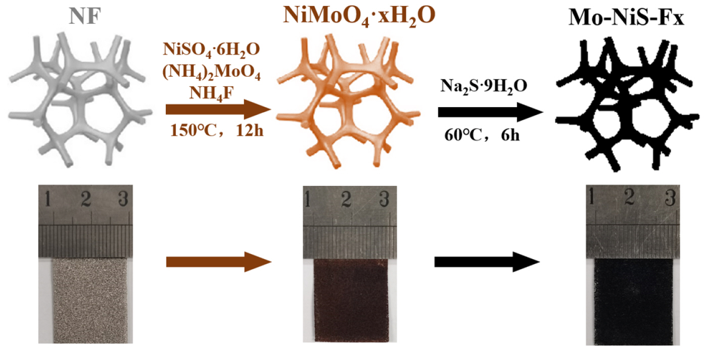
Mo-NiS-Fx was made using the hydrothermal method depicted in Fig. 1. The NF turned brown after the solvothermal technique was used to deposit the precursors of nickel and molybdenum on it. After sulfuring the precursor, a black electrocatalyst was created.
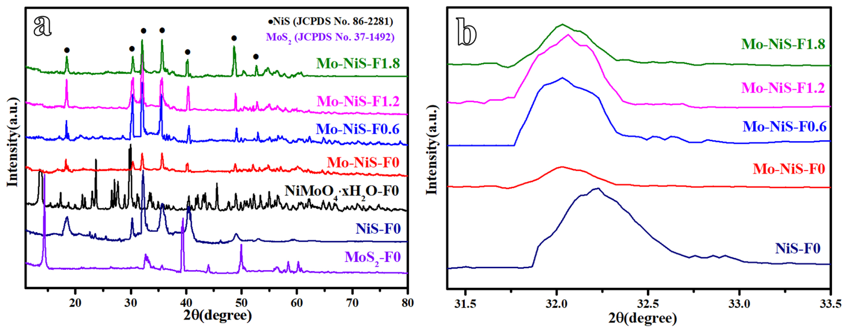
When the samplesŌĆÖ crystal structures were examined using XRD (Fig. 2a), it was possible to determine that the bimetallic precursor was NiMoO4┬ĘxH2O, while the monometallic samples NiS-F0 and MoS2-F0 were NiS (JCPDS No. 86-2281) and MoS2 (JCPDS No. 37-1492) phases, respectively [13]. The precursor was subsequently sulfured. NiS phase was visible in the Mo-NiS-Fx crystal structure (JCPDS No. 86-2281). The corresponding (110), (101), (300), (021), (211), (131), and (401) are represented by the diffraction peaks at 18.4┬░, 30.3┬░, 32.2┬░, 35.7┬░, 40.4┬░, 48.8┬░, and 52.6┬░, respectively. Less impurity peaks were visible in the Mo-NiS-Fx XRD pattern, suggesting that the produced samples were purer. Furthermore, adding NH4F altered the sampleŌĆÖs grain size but did not alter the crystal structure of the sample (Entry 1, Table 1). It was notable that there was no diffraction peak associated with Mo species in the Mo-NiS-Fx XRD pattern. The diffraction peak will vanish if the element has a high dispersion or if its content is below the instrumentŌĆÖs detection limit. In comparison to NiS-F0, the Mo-NiS-Fx diffraction peak migrated to the left, indicating a higher lattice constant and the incorporation of heteroatoms bigger than the main atomic radius (Fig. 2b). Millerite NiS has a lattice constant of 0.9619 nm and is a member of the hexagonal structure. Following Mo doping, the lattice expands and the lattice constant are somewhat raised (Entry 2, Table 1). In the process that yielded Modoped NiS, Mo and Ni underwent isomorphic substitution, and the Mo material was effectively incorporated into the NiS structure. Since the lattice energy of MoS2 is higher than that of NiS [28], during the creation of Mo-NiS-Fx, Mo substitutes the cation in the NiS lattice rather than Ni, which can increase the stability of the structure. Since Mo is somewhat dispersive in this situation, XRD might miss it.
The element content of the sample was then tested using ICP-MS, which allowed researchers to examine the impact of NH4F on the element content in addition to confirming the presence of the element Mo. The element Mo was found in the results, however its amount was low, which may be one of the reasons XRD is unable to detect it (Entry 3, Table 1). Furthermore, the Mo elementŌĆÖs content difference was not significant, suggesting that the addition of NH4F had no effect on the Mo elementŌĆÖs content. S element was evaluated by the element analyzer because it had significant interference in ICP-MS, which caused its detection findings to have a large variance. The findings demonstrated that there was no discernible difference in the S elementŌĆÖs content, suggesting that the addition of NH4F had no impact on the S elementŌĆÖs content (Entry 4, Table 1).
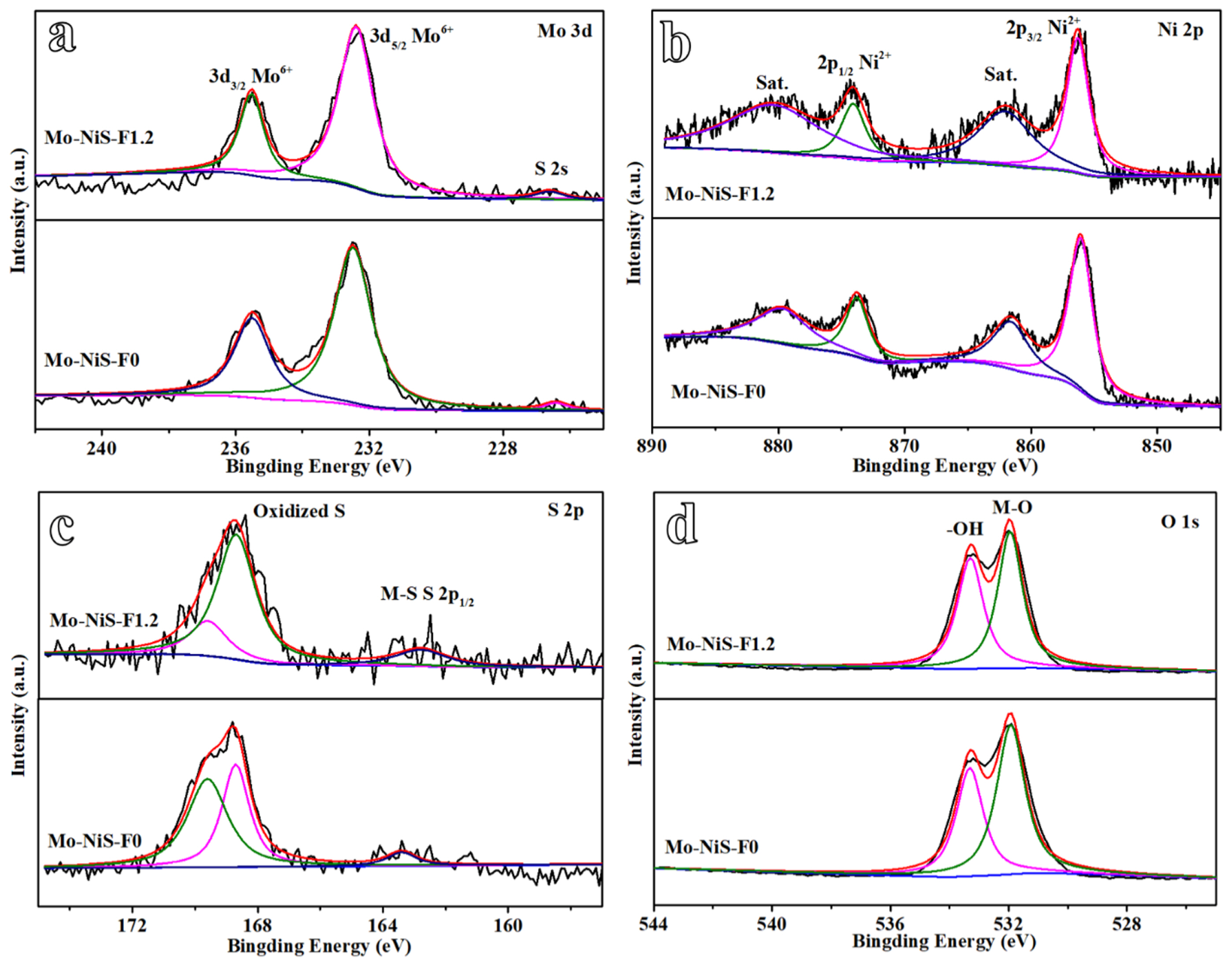
X-ray photoelectron spectroscopy (XPS) was utilized to identify the Mo-NiS-F0 and Mo-NiS-F1.2 in order to examine whether the addition of NH4F will alter the composition and valence state of the element. The MoŌĆōS bond formation was indicated by the peak at 226.6 eV, which was attributed to the S 2s orbital (Fig. 3a) [19]. The two peaks in the high-resolution Mo 3d spectra, 235.5 and 232.4 eV, were attributed to Mo6+. It was demonstrated that the Mo element was doped by substituting Ni to produce the MoŌĆōS bond, which was in line with the XRD findings. The Ni 2p XPS spectrum was shown in Fig. 3b. The satellite peaks were positioned at 862.1 and 880.4 eV, respectively, while the two peaks at 856.3 and 874.1 eV corresponded to Ni2+ [19]. The S 2p spectra of Mo-NiS-F0 and Mo-NiS-F1.2 were separated into three peaks: the MŌĆōS bond was responsible for the peaks at 162.8 eV, while the peaks at 168.7 and 169.6 eV belonged to the sulfates/sulfites generated by the oxidation of the surface S2ŌłÆ in air (Fig. 3c) [19]. The presence of terminal unsaturated S atoms at the NiŌĆōS and MoŌĆōS sites is shown by the S 2p1/2 peak, which is noteworthy since it indicates poor coordination sulfur and may facilitate the development of HER. The sampleŌĆÖs O 1s spectra showed two peaks at 531.9 and 533.3 eV, which, respectively, corresponded to the MŌĆōO bond and the surface hydroxyl group (Fig. 3d). The XPS results showed that NH4F had no effect on the elementsŌĆÖ valence or composition.
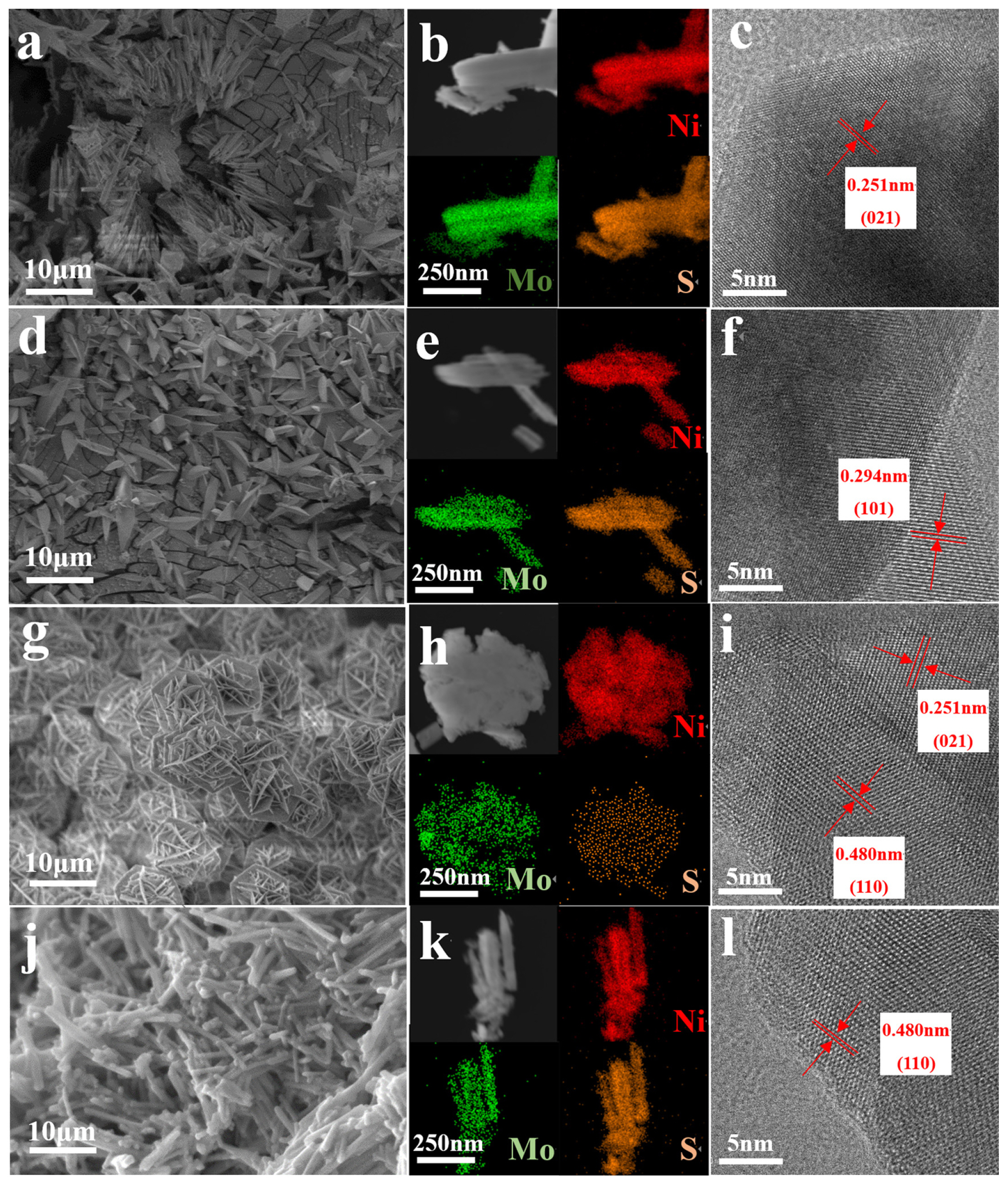
SEM was used to examine the electrocatalystŌĆÖs morphology. Fig. 4 illustrates how varying concentrations of NH4F affect the sampleŌĆÖs morphology, which includes four alternative morphologies: prisms (Fig. 4a), cones (Fig. 4d), flakes (Fig. 4g), and rods (Fig. 4j). When NH4F was not supplied, the Mo-NiS-F0 shape was primarily clustered prisms with collapse at the front end, which may have been brought on by structural damage during the sulfuration process (Fig. 4a). Following the addition of NH4F, the shape of Mo-NiS-F0.6 changed to cones with smooth surfaces (Fig. 4d). Due to their great electronegativity, fluoride anions (FŌłÆ) have been proven to be able to chemically adsorb with dangling bonds, which inhibits crystal development and controls crystal shape [29]. As a result, after adding ammonium fluoride, the morphology of NiS could only grow into a cone rather than a prism shape. Mo-NiS-F1.2 revealed an interlacing flake with a thickness of roughly 0.1 ╬╝m as the mass of NH4F increased. Several flakes combined to form a mesh ball, which was deposited to create a porous material (Fig. 4g). This porous structure is conducive to increase the specific surface area, expose more active sites, and improving the activity of the catalyst. When too much NH4F was injected, Mo-NiS-F1.8 shape was mostly a homogeneous rod with a smooth surface (Fig. 4j). Since NH4F actually functions as a growth inhibitor, the shape of NiS progressively altered from thick and coarse to thin and slender as the concentration of NH4F increased. The morphology of the sample was not regulated after excessive addition of NH4F, which might be due to the corrosion of FŌłÆ and the acid condition of NH4F inhibiting the growth of grain [30,31]. Even though the sampleŌĆÖs shape varied depending on the amount of NH4F added, each sample was firmly grown on NF, ensuring the working electrodeŌĆÖs stability and electrical conductivity. Furthermore, the sampleŌĆÖs element map successfully identified the uniform distribution of Ni, Mo, and S elements (Fig. 4b, e, h, k), demonstrating the effectiveness of the preparation procedure. In conclusion, the addition of NH4F during the hydrothermal process resulted in the creation of electrocatalysts with various morphologies.
ItŌĆÖs also important to keep in mind that various morphologies will reveal different crystal faces in the sample, which could result in variations in catalyst performance. MoŌĆōNiS-F0 exposed the (021) plane (Fig. 4c), Mo-NiS-F0.6 exposed the (101) plane (Fig. 4f), NiS-F1.2 exposed the (110) and (021) planes (Fig. 4i), and Mo-NiS-F1.8 exposed the (110) planes exclusively (Fig. 4l), according to the HRTEM pictures. It is evident that the exposed crystal planes increasingly become single as the concentration of NH4F increases. This phenomenon may be related to the energy of the lattice planes, because FŌłÆ can produce stronger chemisorption with crystal planes that have lower lattice plane energy [32, 33]. A higher atomic density in the crystal plane corresponds to a larger separation among the family of crystal planes, which lowers the lattice plane energy or interatomic binding force. The lattice plane energies of (021) > (101) > (110) are arranged in the following order based on their crystal plane spacings: 0.480 nm of {110}, 0.294 nm of {101}, and 0.251 nm of {021}, respectively. Because of NH4FŌĆÖs limitation effect, NiS preferentially develops along the crystal plane with lower lattice plane energy. Therefore, only the (110) crystal plane with the lowest lattice plane energy was exposed by Mo-NiS-F1.8 as the concentration of NH4F rose (Entry 5, Table 1).
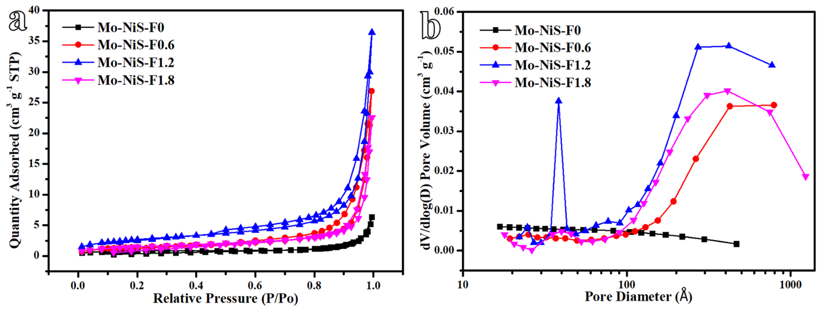
Fig. 5 and Table 1 displayed the nitrogen adsorption-desorption isotherm and pore size distribution of the Mo-NiS-Fx electrocatalyst. The type-IV adsorption isotherm, which is a common property of mesoporous adsorption materials, was evident in Mo-NiS-F0.6, Mo-NiS-F1.2, and Mo-NiS-F1.8 (Fig. 5a). On the other hand, Mo-NiS-F0ŌĆÖs type-IV trait was less obvious. Based on the isotherm linear plot, Mo-NiS-F1.2 was shown to have the highest capacity for adsorption of nitrogen, and its BET surface area peaked at 9.76 m2 gŌłÆ1 (Entry 6, Table 1). Furthermore, type-H3 hysteresis loops were seen in Mo-NiS-F0.6, Mo-NiS-F1.2, and Mo-NiS-F1.8. These loops typically indicated that the slit holes did not show adsorption saturation in the high-pressure area. Cones, flakes, and rods were stacked to create the slit holes in Mo-NiS-F0.6, Mo-NiS-F1.2, and Mo-NiS-F1.8, respectively. With the greatest number of slit pores, the flakes that constituted the three-dimensional hydrangea had the strongest capacity for nitrogen adsorption. Mo-NiS-F0 had a prismatic shape and no slit pores were formed. Mo-NiS-F1.2 and Mo-NiS-F1.8 were primarily small mesoporous (2ŌĆō4 nm), big mesoporous (5ŌĆō50 nm), and microporous (50ŌĆō100 nm), according to the pore size distribution plot (Fig. 5b), suggesting that rods and flakes form a multi-level pore structure. Mo-NiS-F0 exhibited no pore development, whereas Mo-NiS-F0.6 displayed large mesoporous (5ŌĆō50 nm) and microporous (50ŌĆō100 nm) structures. Mo-NiS-F1.2ŌĆÖs pore volume peaked at 0.05 cm3/g, suggesting that the multi-layer pore structure would increase the pore volume (Entry 7, Table 1). Furthermore, Mo-NiS-F1.2 had an average pore diameter of 186.08 ├ģ, which was less than that of Mo-NiS-F0.6 (205.39 ├ģ) and Mo-NiS-F1.2 (261.96 ├ģ), because of the abundance of small mesoporous pores (2ŌĆō4 nm) in Mo-NiS-F1.2 (Entry 8, Table 1). As a result of its multilayer pore structure created by stacking flakes, Mo-NiS-F1.2 demonstrated the highest BET surface area and pore volume (Table 1), which aided in the creation of more active sites.
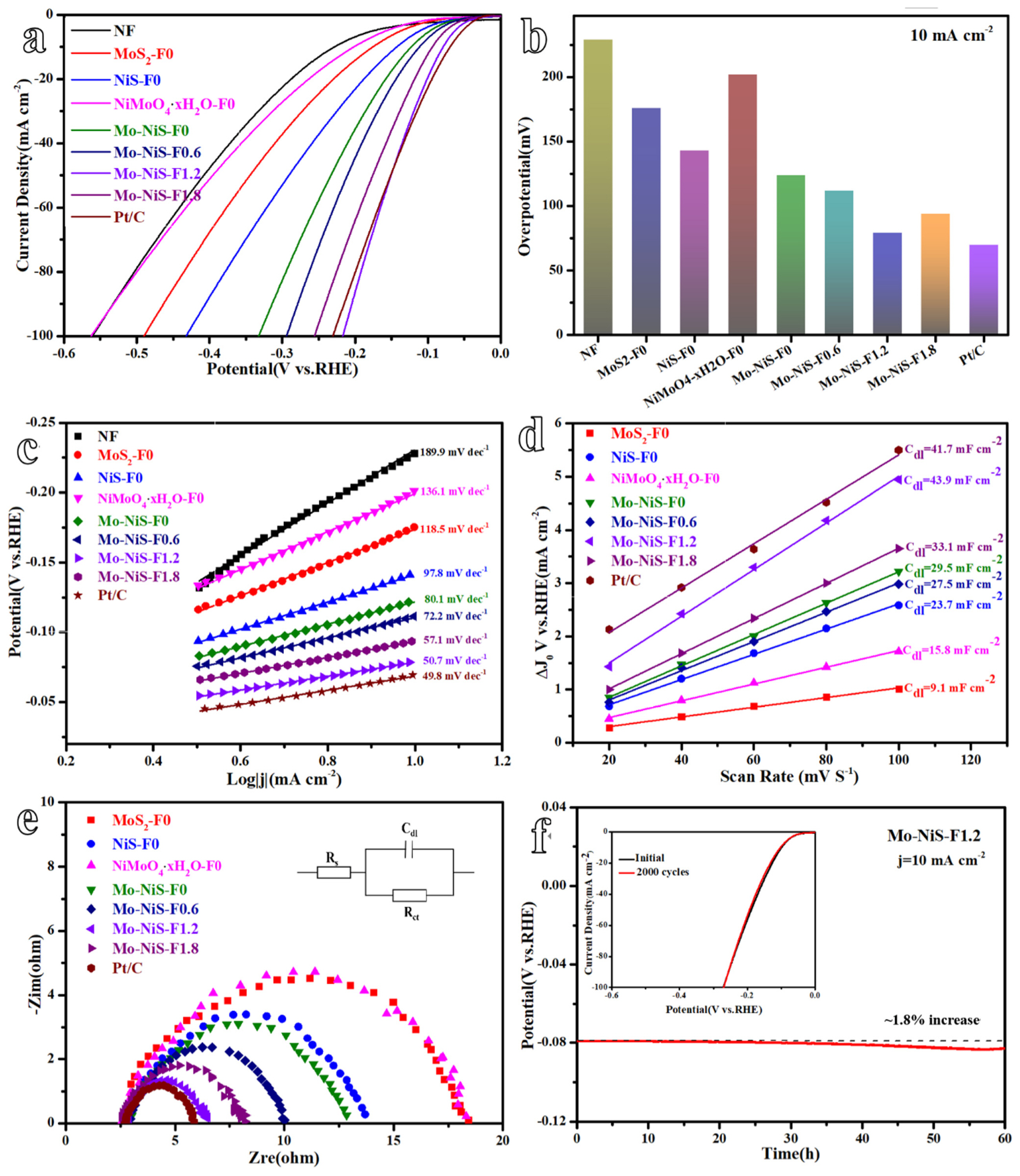
Three electrode systems were then used to examine the hydrogen evolution performance of Mo-NiS-Fx electrocatalysts with various morphologies. First, linear sweep voltammetry (LSV) was used to evaluate the sampleŌĆÖs overpotential and current density curves at a scanning rate of 5 mV sŌłÆ1 (Fig. 6a). Here, the comparable data was the overpotential at a current density of 10 mA cmŌłÆ2 (Fig. 6b). At a current density of 10 mA cmŌłÆ2, the overpotential of NF was 229 mV, significantly more than that of MoS2-F0 (176 mV) and NiS-F0 (143 mV). The precursor NiMoO4┬ĘxH2O exhibited an overpotential of 202 mV, but the overpotential of Mo-NiS-F0 decreased to 124 mV, indicating the significance of sulfuration for the hydrogen evolution mechanism. Additionally, it was observed that the addition of Mo species on the basis of NiS-F0 greatly enhanced the hydrogen evolution performance of Mo-NiS-F0, suggesting that the coupling and synergy between active substances had a major HER-promoting effect. Following this, Mo-NiS-F-0.6, Mo-NiS-F1.2, and Mo-NiS-F1.8 displayed overpotentials of 111 mV, 79 mV, and 94 mV at 10 mA cmŌłÆ2. These overpotentials were associated with the sample morphology that was modified by NH4F. The BET surface area of Mo-NiS-F0.6 (cones), Mo-NiS-F1.2 (plates) and Mo-NiS-F1.8 (rods) was higher than that of Mo-NiS-F0 (prisms), especially the BET surface area of Mo-NiS-F1.2 with plate structure was as high as 9.76 m2 gŌłÆ1, which was conducive to exposing more active sites. On the other hand, the catalystŌĆÖs HER performance could potentially be impacted by the exposed crystal plane. Through the DFT calculation, the researchers found that the higher the lattice plane energy, the smaller its adsorption free energy of hydrogen atom (╬öG(H*)), which means the stronger the adsorption [32,33]. Nonetheless, a high capacity for hydrogen adsorption in HER, which was detrimental to the hydrogen desorption reaction [5]. NiS (110) exposed in Mo-NiS-F1.2 has the lower lattice plane energy, indicating that ╬öG(H*) is larger at this time, but hydrogen desorption is also more straightforward. It is more favorable for the creation and escape of reaction intermediates in this instance. Therefore, the (110) plane with the lower lattice plane energy exposed by Mo-NiS-F1.2 helps to improve its HER activity. In addition, Pt/C as a control had an overpotential of only 69 mV at 10 mA cmŌłÆ2, which was still higher than that of Mo-NiS-F1.2 (79 mV). The noble metal catalyst continued to operate exceptionally well in the hydrogen evolution process. However, Pt/C (231 mV) had a greater overpotential at 100 mA cmŌłÆ2 than that of Mo-NiS-F1.2 (217 mV), which was associated with how the two catalysts were prepared. The Pt/C electrocatalyst prepared by the impregnation method cannot be firmly attached to NF, and a large number of bubbles formed at high current density will make Pt/C fall off NF, resulting in reduced catalytic performance. Mo-NiS-F1.2, the self-supported electrode, is securely attached to NF, guaranteeing its catalytic activity. The three factors that affect HER activity are lower lattice plane energy of exposed crystal plane, higher BET surface area and direct growth on NF. The excellent effect of Mo-NiS-F1.2 is the result of the combined action of the above three factors. Although Mo-NiS-F1.8 has exposed (110) crystal surface, its BET surface area is small, which limits its HER performance.
The logarithm of current density [log(j)] and overpotential curve (i.e. Tafel curve) can be drawn from the LSV curve (Fig. 6c). The smaller the Tafel slope, the faster the current density increases, the smaller the overpotential changes, and the better the electrocatalyst performance. The Tafel slopes of NF, Mo-NiS-F0, Mo-NiS-F1.2 and Pt/C were 189.9 mV decŌłÆ1, 80.1 mV decŌłÆ1, 50.7 mV decŌłÆ1 and 49.8 mV decŌłÆ1, respectively. After NH4F was added to alter the catalyst shape, the Tafel slope of Mo-NiS-F1.2 could be greatly decreased and was nearly identical to that of the precious metal catalyst. Tafel slope reveals that the kinetic process of Mo-NiS-F1.2 includes Heyrovsky reaction and Volmer reaction, and the rate-determining step is Heyrovsky reaction. The Tafel curve can be used to compute the exchange current density (j0) that represents the intrinsic activity of HER. For NF, Mo-NiS-F0, and Mo-NiS-F1.2, the corresponding j0 values are 0.39 mA cmŌłÆ2, 0.69 mA cmŌłÆ2, and 1.26 mA cmŌłÆ2. Consequently, Mo-NiS-F-1.2 had the highest intrinsic HER activity.
The catalystŌĆÖs cyclic voltammetry curve (CV) was measured at various scanning rates, and the CV curve could be used to determine the charging current at various scanning rates (Fig. S1). The double-layer capacitance (Cdl), which assesses the electrodeŌĆÖs electrochemically active area (ECSA), is the slope of the line that connects the charging current and scanning rate (Fig. 6d). The larger the Cdl, the higher the electrochemical active area of the electrocatalyst. Mo-NiS-F0, Mo-NiS-F1.2, and Pt/C had Cdl values of 29.5 mF cmŌłÆ2, 43.9 mF cmŌłÆ2, and 41.7 mF cmŌłÆ2, in that order. Based on this, the Mo-NiS-F0, Mo-NiS-F-1.2, and Pt/C ECSA values were 737.5 cmŌłÆ2, 1097.5 cmŌłÆ2, and 1042.5 cmŌłÆ2, respectively. Mo-NiS-F-1.2 had the highest electrochemically active area, which was related to its flake shape and large specific surface area, providing more pathways for close contact of electrolyte solutions. It was worth noting that the ECSA of each catalyst was lower than its BET surface area because not all surface sites were active.
Next, electrochemical impedance spectroscopy (EIS) was used to measure the electrocatalystŌĆÖs Nyquist diagram. The electron transfer resistance (Rct), which shows the efficiency of the transfer between the electrocatalyst surface and the electrolyte, is represented by the semicircle diameter in the Nyquist diagram (Fig. 6e). The Rct values of Mo-NiS-F0, Mo-NiS-F0.6, Mo-NiS-F1.2, and Mo-NiS-F-1.8 were 10.3 ╬®, 7.5 ╬®, 4.0 ╬®, and 5.7 ╬®, respectively, according to the results. In comparison to Mo-NiS-F0, Mo-NiS-F0.6, and Mo-NiS-F1.8, the Mo-NiS-F1.2 displayed a reduced Rct. This suggests that a lower electrochemical impedance facilitates faster electron transfer, which in turn ensures a faster hydrogen evolution reaction. It is possible that kinetics, rather than mass transfer, govern the hydrogen development process in the low frequency area, which accounts for the absence of Warburg resistance in the equivalent current diagram [34].
Another crucial factor in assessing a catalystŌĆÖs performance is stability. Chronopotentiometry was used to investigate the stability of Mo-NiS-F1.2 (Fig. 6f). For 60 h at 10 mA cmŌłÆ2, Mo-NiS-F1.2 stayed stable with only a 1.8% increase in overpotential. The LSV curve remained unchanged after 2000 cycles, which proved that the HER performance of Mo-NiS-F1.2 with flakes structure did not decrease significantly (Fig. 6f). Mo-NiS-F1.2 retained the NiS phase and flake morphology, according to SEM and XRD characterization of the reaction samples (Fig. S2a, b). The Mo-NiS-F1.2 demonstrated outstanding HER performance and stability, as confirmed by the data. Furthermore, after 60 hours of stability testing, the overpotentials of Mo-NiS-F0, Mo-NiS-F0.6, and Mo-NiS-F1.8 increased by 0.8%, 1.1%, and 0.9%, respectively (Fig. S2cŌĆōe). It is evident that the intricacy of the structure would result in a decrease in stability, but this decrease may be disregarded given the catalystŌĆÖs excellent performance.
Lastly, Table 2 provided an overview of the published Mo-Ni-S based electrocatalysts. It was evident that the previous electrocatalystsŌĆÖ morphology was still being developed in the direction of a particular morphology, namely one that was porous and had a high BET surface area. The Mo-NiS-F1.2 electrocatalyst, which was created in this work, had an overpotential that was much lower than other Mo-Ni-S-based electrocatalysts that have been published. Its Tafel slope also decreased. In addition to providing additional active sites, the multi-layer pore structure created by the stacking of flakes in Mo-NiS-F1.2 also provided routes for gas transport. The evolution of morphologies will be a crucial area of electrocatalyst research.
4. Conclusions
To summarize, a two-step solvothermal approach was utilized to successfully synthesis Mo-NiS-Fx electrocatalysts with varying morphologies, such as prisms, rods, flakes, and cones, using NH4F of varying mass. The Mo-NiS-F1.2 with flakes structure was one of them; it was a layered porous structure with a high specific surface area that could both enhance the vent ability and reveal rich active spots. Its outstanding HER activity was further guaranteed by the coupling and synergy of the active ingredients. With a Tafel slope of 49.8 mV decŌłÆ1 and an overpotential of only 79 mV at 10 mA cmŌłÆ2, Mo-NiS-F1.2 demonstrated exceptional HER performance in alkaline conditions, matching that of precious metal catalysts. The experimental results showed that the electrode materials with high specific surface area and porous structure were conducive to the electrocatalytic reaction. Simultaneously, NiS (110) plane exposed in Mo-NiS-F1.2 has the lowest lattice plane energy, making it a low energy to adsorb and desorption hydrogen, which is conducive to the formation and escape of reaction intermediates. In addition, the prepared catalyst was uniformly covered with NF, ensured the conductivity and stability of the catalyst, where Mo-NiS-F1.2 could run stably for 60 h at 10 mA cmŌłÆ2. The above three advantages play an active role in improving the catalytic performance. In this work, Mo doped nickel-based sulfide catalysts with various morphologies were constructed, which would provide reference for the preparation of advanced electrocatalysts for HER.