1. Introduction
The use of fossil fuels in vehicles has resulted in air pollution and climate change and thus, the efforts to reduce these emissions as well as find alternatives to fossil fuels are now a significant focus of scientific inquiry. In addition to the air pollution caused by the release of SOx, NOx, dust, soot, and smoke into the atmosphere during the combustion of fossil fuels, these are the major cause of global warming [1]. Another issue is the limited reserves of fossil fuel oil, coal and natural gas which may run out in around 35, 107, and 37 years, respectively [2]. Moreover, due to the intermittent nature of renewable energy, converting vehicles from fossil fuels to renewable fuels is facing difficulties. The present growth of “hydrogen economy” [3] in which energy supplied to vehicles would depend on hydrogen is attractive because the combustion of hydrogen produces heat and water as byproducts without any emission instead of green-house gases. However, hydrogen as a renewable energy faces several limitations ranging from hydrogen production, storage, transportation, and utilisation [4].
Recently, proton exchange membrane electrolysis cell (PEMEC) system has attracted considerable attention and competition in the hydrogen industry due to its significant capability for the efficient hydrogen production. The optimisation of design, operational parameters, and material properties relevant to PEMEC is thus very much essential. The ideal setup and operational requirements that result in higher performance in PEM electrolysis cells have been the subject of numerous investigations [5,6]. The oxygen evolution reaction (OER) at anode (Eq. (1)) and the cathode reduction reaction or hydrogen evolution reaction (HER) (Eq. (2)) of a PEMEC when external direct current (DC) is applied are presented below:
Anode reaction:
Cathode reaction:
The important components of the proton exchange membrane electrolysis cell (PEMEC) are the HER catalyst at cathode, the OER catalyst at anode, the gas diffusion layer (GDL), and the current collector bipolar plates (BPPs). The platinum (Pt) has been the most popular cathode catalyst for PEMEC [7] where the hydrogen evolution reaction (HER) [8] takes place. On the other side iridium oxide (IrO2) is the most popular anode catalyst for oxygen evolution reaction catalyst due to the low Tafel slope [9]. The gas diffusion layer is also one of the most important components of PEMEC for electrode manufacturing, due to the excellent electronic conductivity and high porosity, carbon paper or carbon cloth are frequently employed for gas diffusion layers [10]. The current collector are the bipolar plates with flow channel are made of metal or polymer mixed with carbon or graphite [11]. The solid electrolyte Nafion® membrane, which is same as the electrolyte membrane used in proton exchange membrane fuel cell (PEMFC) are also preferred for the PEMEC due to very high proton conductivity in the order of 0.1 S/cm [12].
The major output, i.e., hydrogen gas/H2 should be produced at a maximal rate with low power consumption. The feed water temperature also has a significant impact on the production of hydrogen because raising the feed temperature enhances the kinetics of both HER and OER reactions. However, the temperature also has an impact on how the electrolyser manages its water supply [13], as the membrane electrolyte dehydrates and the ohmic resistance rises with the increase in water temperature [14]. Moreover, due to the complicated kinetics of the OER reaction, anode stoichiometry also restricts the production of hydrogen in the PEMEC [15]. Thus, the main goal of the current study is to determine the best operating parameters for the PEMEC using the response surface methodology (RSM) approach in order to achieve the highest possible hydrogen production and hydrogen production per unit of power consumed. The box behnken design (BBD) experimental design could be used to thoroughly examine the impact of independent variables on the hydrogen production viz the oxygen side (anode) catalyst loading, feed water temperature, and applied current on hydrogen production. To illustrate the relationship between independent factors and the responses, a mathematical model needs to be developed [16].
The parameters must be tuned during the operation of the cells in order to get the desired response, which is often done by adjusting one parameter while the values of all other parameters are fixed to a certain value when experimental optimization is adapted [17]. However, doing so there is a loss of valuable resources and duration of the experiment increases tremendously. Nowadays, there are various numerical studies that have been carried out using a variety of techniques in an effort to minimize the major issues of experimental optimization [18–20]. The most popular among all these investigations are design of experiments (DOE) and response surface methodology (RSM). Due to the limited number of tests, these techniques have been used in the optimization of process parameters over the past 10 years. In the industry, DOE applications are fairly wide-spread [19,21]. The RSM is a statistical and mathematical technique used to optimize complex systems or processes where the correlation between input variables (factors) and output /responses is not linear and also involves multiple variables. The RSM involves the creation of polynomial equations to link the factors and responses [22,23]. The RSM-based optimization studies can be divided into three steps. To obtain information about the range of the system or process variables, a series of well-planned experiments are carried out in the first step. In the second step interaction between the input variables and the output responses are established. In the final step, a mathematical model, i.e., typically a regression model is built based on the experimental data. The “response surface” is the name of this paradigm. Using optimization approaches, it is possible to identify the input variable settings that provide the desired or best output responses after the response surface model has been built. The optimization algorithms, such as gradient descent, genetic algorithms, or other numerical methods, are commonly used in this step [24].
Most of the process optimization studies are found for PEMFC, direct ethanol fuel cell (DEFC), direct methanol fuel cell (DMFC), microfluidic fuel cell (MFC) using RSM in the open literature. However, no such studies on the process optimization of PEMEC using RSM by employing box behnken design (BBD) is found in the open literature. Carton et al. (2010) [25] carried out the performance optimisation of a PEMFC by investigating the effects of hydrogen flow rate, air flow rate, and hydrogen pressure at the inlet using the three different types of flow fields viz parallel, serpentine, and maze. The results generated by the DOE show that the serpentine flow plate design is far more effective than the parallel flow plate design or the maze in terms of the current and voltage response of the polarisation curve. On the other side, it was seen that the parallel flow plate functioned rather well at higher pressures. Taymaz et al. (2011) [26] maximized the direct methanol fuel cell power density using RSM with methanol flow rate, oxygen flow rate, fuel temperature, humidification temperature, and cell temperature as the input variables. The optimal operating conditions are crucial for fuel cell performance. Increasing the methanol flow rate is expected to increase cell performance. The excess water on the cathode side reduces cell performance. High humidification temperatures in the cathode side of the cell caused a decrease in the cell performance. Similarly, Silvia et al. (2012) [27] optimized the process parameters of a DMFC in order to achieve the highest power density as a function of temperature, methanol concentration, relative humidity of air, air flow rate, and methanol flow rate. In another study, various effective variables like temperature, methanol content, and air flow rate within a more constrained range were optimized by the RSM. The experimental value, averaged over four trials, was 69.7 mW/cm2, while the interpolating model projected a maximum power density of 69.8 mW/cm2 at 90°C, methanol concentration of 1.42 M, and air flow rate of 875 mL/min. Kanani et al. (2015) [28] studied the impact of operational variables such as cathode stoichiometry, anode stoichiometry, gases inlet temperature, and cathode relative humidity on the power density of the cell by RSM modelling using BBD for a single serpentine flow field based PEMFC. The minimal cell power is produced by high cathode stoichiometry and low anode stoichiometry; in contrast, the most power is produced by medium fuel and oxidant stoichiometry. The best performance could be achieved by selecting a certain value for the anode stoichiometry, cathode stoichiometry, and relative humidity, according to the results. The experimental tests were used to assess the model’s predictions, and the results show good agreement across a variety of parameter values.
Apart from the RSM optimisation, in some studies, Taguchi optimisation approach was also used. Toghyani et al. (2019) [18] developed a thermodynamic model for proton exchange membrane electrolysis cells where Taguchi optimisation approach was used to examine how seven different operational parameters affected cell performance. The findings show that the ideal conditions are attained at the lowest possible levels of membrane thickness, cathode pressure, and anode pressure, as well as at the maximum working temperature, membrane water content, cathode and anode exchange current density. With a contribution of 67.15%, the anode exchange current density had a significant impact on the electrolyzer voltage. However, the anode pressure and membrane water content only have a small impact having their contribution of 1.1% and 0.42%, respectively. Falcão et al. (2020) [29] developed a mathematical model on PEM electrolyser models which was used to predict the cell voltage applied for the H2 generation. In a T-shaped air breathing microfluidic fuel cell (MFC), Panjiara et al. (2020) [30] optimised the input variables which include glycerol/fuel concentration, anode electrolyte/potassium hydroxide (KOH) concentration, anode electrocatalyst loading, and cathode electrolyte/KOH concentration using RSM by employing BBD to maximise power generation for glycerol-based MFC. The RSM model predicted the optimum parameters of 1.07 M of glycerol, 1.62 M of anode electrolyte, 1.12 mg/cm2 of anode electrocatalyst loading, and 0.69 M of cathode electrolyte to achieve highest power density. The actual/experimental power density (2.76 mW/cm2) and predicted power density (2.79 mW/cm2) showed an insignificant divergence of only 1.07%. Choudhary et al. (2021) [31] optimized the process parameters of direct ethanol fuel cell using RSM with BBD to maximise response, i.e., power density, where the key operating variables were ethanol concentration, anode electrocatalyst loading, and operating temperature. The RSM model yielded a maximum peak power density of 22.10 mW/cm2, which was confirmed experimentally with the optimized parameters of 2.03 M ethanol concentration, 1.14 mg/cm2 anode electrocatalyst loading, and 79.48°C operating temperature. The validation of model revealed that the computed value of 22.10 mW/cm2 by the model was very close to the experimentally measured value of the highest power density attained under optimum conditions (21.53 mW/cm2). The RSM optimization findings showed that the operating cell temperature, anode electrocatalyst loading, and ethanol content had the greatest effects on the power density of DEFC.
In the study of Kahveci et al. (2022) [20], RSM was carried out on the hydrogen based PEMFC stack via central composite design (CCD), for maximizing the current density through the experimental analysis of operational factors or input variables such as cathode and anode flow rate, humidification temperature, and cell temperature. It was observed that the reaction rate increases with the increase in temperature and thus, the flow rate ought to be raised. The maximum current density values of 313.66 mA/cm2, 336.75 mA/cm2, and 323.48 mA/cm2 were attained at flow rates of 1 L/min, 1.3 L/min, and 1.6 L/min, respectively. Ozdemir et al. (2023) [32] used RSM and employed CCD to optimise the effect of operating temperature, pump speed, and cell voltage on both current and hydrogen flow rate within the commercial PEM electrolysis cell. However, they did not mention the cathode or anode electrocatalyst and electrolyte used in order to optimize both the current supplied and applied voltage to the electrolyzer for the maximum H2 production rate. Table 1 shows various optimization methods being applied for different fuel cell and electrolytic cell by optimizing various input parameters to maximize the output/responses.
It is seen from the thorough literature, the RSM modelling has been used for the optimization of process variables of various types fuel cell mainly. However, RSM has not yet been used for the optimization of effective process variables of PEMEC where the power consumption is minimized for maximizing the production rate of H2 and hydrogen production rate per unit power consumption. Thus, in the present study, effective process variables of a laboratory fabricated PEMEC such as the anode catalyst loading, current supplied, and water inlet temperature via the BBD method to maximize the rate of H2 production and rate of hydrogen production per unit wat are the main focus of this present work. The developed RSM model equation could reasonably predict the optimized process parameters which are in the good agreement with the experimental ones for the desired responses. Thus, could save both the costly resources and time.
2. Experimental
2.1 Materials and method
The electrocatalyst used for the fabrication of cathode or hydrogen electrode of the PEMEC was commercial platinum/acetylene carbon black ((Pt) (40 wt%)/CHSA) (Alfa Aesar, USA). The electrocatalyst used for making the anode or oxygen electrode was commercial IrO2 (Alfa Aesar, USA). The gas diffusion layer, which serves as a support for electrocatalyst ink deposition and subsequent manufacturing of electrodes was made of Toray Carbon Paper TGP-H-60 (Alfa Aesar, USA). The electrocatalyst ink was prepared using polytetrafluoroethylene (PTFE) dispersion (60 wt%; Sigma Aldrich, USA) and ionomeric solution Nafion® dispersion (5 wt%; Alfa Aesar, USA) and acetylene black carbon for electron transport within the electrode as a binder. The oxygen electrode was fed with distilled water. The stainless steel with serpentine flow channels were used as current collectors. The fuel cell used Nafion - 117 membrane (Alfa Aesar, USA) as the electrolyte for the transport of hydrogen (H+) ions from anode to the cathode side.
2.2 Electrode preparation
The required quantity of commercial electrocatalyst Pt (16:4)/CAB (1 mg/cm2) for the cathode, Nafion® dispersion, PTFE dispersion, activated carbon/acetylene black carbon, and isopropanol were mixed thoroughly using ultrasonication for 30 minutes to make the cathode electrocatalyst ink. Using a paintbrush, the homogenous electrocatalyst ink was applied to the GDL (3 cm×3 cm, thickness - 150 μm) uniformly, and it was then dried for one hour at the temperature of 80°C in an oven [33]. To activate the electrode by unblocking the pores, the manufactured cathode was sintered at a temperature of 280°C for 3 hrs. The anode/oxygen electrode was manufactured in similar manner to that of cathode with the exception, IrO2 used in place of Pt (16:4)/CAB for oxygen electrodes with varied loading of cathode electrocatalyst [34].
2.3 PEMEC performance test setup
Fig. 1 shows the experimental setup of the proton exchange membrane electrolytic cell (PEMEC) which was designed and fabricated at IIT (BHU) laboratory. The negative terminal of the power source was connected to the hydrogen (H2) electrode or cathode, while the positive terminal was connected to the oxygen (O2) electrode or anode of the PEMEC. The cell was coupled to a regulated DC power source (Aplab power, India). A peristaltic pump (Electrolab, India) was used to deliver feed water at a rate of 3.5 mL/min to the O2 electrode/anode. The feed water temperature was maintained at desired level using a heating mantle. The water displacement method, which tracks the volume of water displaced from an inverted water-filled measuring cylinder, was used to measure the H2 gas produced in the H2 electrode/cathode. To do this, the outlet of one side of the electrode was sealed with wax to prevent hydrogen escaping from other side, i.e., of the flow channel. As a result, the hydrogen produced travels only to the outlet direction.
The manufactured electrodes, as described in the section 2.2 were installed within the PEMEC using clamping method [35]. The membrane electrolyte Nafion® was placed in between anode and cathode to make membrane electrode assembly by clamping method with the help of nuts and bolts at the four corners, keeping the current collectors over the electrodes in both the sides.
3. Statistical analysis
The RSM design was used to maximise the system’s responsiveness as well as to provide a model equation between an input parameter and its output. The model’s primary benefit over other DOE techniques is that it incorporates both the individual factor and interacting term which effects on the response-variable [21]. To achieve maximal hydrogen production and to maximise the hydrogen produced per unit watt from the PEMEC, BBD was employed in the RSM. For statistical analysis, the Design Expert 7.0 programme (Stat-Ease, Inc., Minneapolis, MN, USA) was used. The BBD is beneficial when quadratic interactions between factors and responses are anticipated. Without thoroughly examining every potential combination, this experimental design chooses specified degrees of characteristics to be investigated, including central points (Cp) and star points [22]. The approach reduces the number of experimental runs while accurately describing the relationship between factors and responses by carefully selecting these points. This makes it a useful tool for determining the best process conditions and comprehending interaction of different factors interact without taking up a lot of time or resources [36].
Numerous factors, including anode and cathode electrocatalyst loading, operating cell temperature, water flow rate and applied current, affect the performance of the PEMFC. However, it can be shown from the published literature that among all these parameters, O2 electrocatalyst loading, feed temperature, and current supplied have the greatest effects on PEMEC performance [20,30,37]. The input parameters were chosen based on the significant variation of the response with a minute change in the input parameter. Additionally, preliminary research revealed that the three effective parameters viz O2/anode electrocatalyst loading (A), current supplied to the cell (B), and water inlet temperature (C) have a significant impact on the PEMEC response, i.e., the rate of hydrogen production and the rate of hydrogen production per unit watt consumption. The range of A is taken from 0.5–2.5 mg/cm2, B is selected from 0.2 A to 0.4 A and C is chosen from 35°C to 65°C (Table 2).
The range of A and C have been established based on the available literature [14,33]. The range of B was found out from the data plot presented in Fig. 2. It is seen from the Fig. 2 that the power consumption rises as the supplied current is increased from low values to high values, and so does the pace of hydrogen production rate. The range of input element ‘B’ was chosen as 0.2 to 0.4 A where the hydrogen production is maximum and the required power consumption is low for that production. It means the electrolysis efficiency would be high in this applied current range (Fig. 2). This range is required to be determined in order to find the optimal range of current for operating the fuel cell. It is observed from experimentation that this optimum range remained same for the cases of different anode electrocatalyst loading as well as different water inlet temperature.
The supplementary figures Fig. S1–S3 show the effect of the selected input variation on the PEMEC performance. Fig. S1a shows the production of hydrogen with time for varying anode loading. Whereas Fig. S1b shows the hydrogen production rate per unit power consumption with varying anode loading ranging from 0.5 mg/cm2 to 2.5 mg/cm2, with 1.5 mg/cm2 requiring the least amount of time to produce 20 mL of H2 is shown in Fig. S1a. The maximum value is reached with a loading of 1.5 mg/cm2, according to Fig. S1b. Fig. S2a shows the relationship between the current supplied and the time needed to produce 20 mL of H2 is shown. A current supply of 0.4 A results showed the shortest time needed. The dependence of hydrogen generation rater per unit power consumption and the current supplied to the cell is depicted in Fig. S2b, with 0.2 A serving as the maximum. The minimum time required for the production of 20 mL of H2 occurs at the temperature of 50°C. Fig. S3a shows the relationship between feed (water) temperature and production time. Fig. S3b shows the relationship between H2 production per unit watt consumption for varied feed temperatures and maximum value is achieved when the temperature was at 50°C, as shown in Table S1–S3 shows the values of hydrogen production rate (mL/min), power consumption (W) and hydrogen production rate per unit watt (mL/min·W) for the different input parameters. The projected model, as shown in Table 2, includes three variables: current delivered, O2 electrode catalyst loading, and feed temperature.
The variables in Eq. (3) are denoted by k, the number of experimental factors, and cp, the number of central points. There were a total of 17 tests that had to be carried out. 12 of the 17 experiments represent the face points, while 5 were performed to forecast the model’s experimental error. Out of all the models, the quadratic model [22] was chosen because it had the best fit, a significant response (P < 0.05), a P-value > 0.05 for poor fit, and a high determination coefficient (R2) value. According to the BBD approach Eq. (4), the findings were fitted into a second-order polynomial equation.
Y represents the predicted response, xi and xj are the independent factors which are being studied to maximize the response βo is the model prediction coefficient for intercept, βi, βii, and βij are the coefficient which show the linear, quadratic and interaction parameter effects.
The analysis of variance (ANOVA), degree of freedom (DF), regression coefficient values, P and F values, as well as other parameters, were used to examine the performance of the chosen model. Three-dimensional graphical and contour plots were used to assess the impact of independent variables on the response were examined.
4. Results and Discussion
4.1 ANOVA analysis and model development
The response to the various input factors, mainly the experimental hydrogen production rate and hydrogen production rate per unit power consumed, i.e., electrolysis efficiency are represented as R1 and R2, respectively. The experimental responses R1 and R2 are compared to the predicted hydrogen production rate and hydrogen production rate per unit power consumed values obtained from the RSM model, as is shown in Table 3. The experimental results and RSM model predicted values presented in Table 3 are generally close to one another, indicating the model’s dependability. The predicted maximum responses of R1 (max(R1)), R2 (max(R2)) and minimum responses of R1 (min(R1)) and R2 (min(R2)) were obtained for the input variables of A, B and C which are shown in Table S4. In order to achieve the desired response, maximisation of both R1 and R2 is required, resulting in maximum hydrogen production and minimal power consumption but the responses R1 and R2 behave like increasing and decreasing function with respect to the current supplied. To achieve the maximisation of both the responses, predicted values of R1 and R2 are first normalised or scaled according to their maximum and minimum values, then their sum is calculated to generate R3, as shown in Eq. (5), which is then again maximised using the BBD model. The ideal settings for producing hydrogen have been determined for running the PEMEC by taking note of the respective input conditions and the corresponding input factor values for anode/O2 catalyst loading (A), current supplied (B), and water inlet temperature (C), where the R3 response is maximised from the Eq. (5) as presented below:
Table S5 shows the experimental results for the amount of hydrogen produced and the time required to produce it under the specified input experimental conditions. The responses R1, R2, and R3 are modelled using the equation of a second order polynomial as is shown in Eq. (4).
Table S6–S8 show the analysis of variance (ANOVA) statistics for the responses R1, R2, and R3 in the quadratic model. The two parameters that serve as the foundation for calculating the significance of the independent variables are F-value and P-value. Due to the high F values 69.26 (R3), 4231 (R2), and 83.47 (R1) and low P values of 0.0001 for all three responses, which demonstrate the adequacy of the model constructed for all three responses. If variance analysis were to be conducted on the developed model, the corresponding values of R2 and Adjusted R2 for response R3, which is the response from which the input optimal conditions are noted, would be 0.9908 and 0.9789, and the smaller value of standard deviation (SD - 0.079), along with R2 tending to unity, would show that the predicted R3 values are close to the experimental R3 values.
Adeq. Precision gauges the signal-to-noise ratio, and often a value greater than 4 is necessary. The value of R3 in this instance is 26.471, indicating that the precision is suitable. Additionally, the high precision experimental design of the model is reliable as evidenced by the low value of the coefficient of variation (CV % = 3.31). The P-value for the “lack of fit” is equal to 0.5261 (Table S8), which is greater than the conventional significance level value (α= 0.05) for the null hypothesis to be valid and suggests that the model developed is consistent for response R3. This is crucial information. Similarly in the cases of R2 and R1 the experimental model which has been developed was validated as shown in the above fashion.
In the cases of R1, R2, and R3, the P-values of the input factors for linear terms (A, B, and C) were all lower than 0.05, indicating that these factors had a significant impact on the answers. While R1 is unaffected by any of the interaction parameters (Table S6), R2 is affected by both AB and BC (Table S7), while R3 is influenced by the interaction parameter AB (Table S8) since their P values are less than the significance level (α = 0.05). The quadratic terms (A2, B2, and C2) for each of the three replies (R1, R2, and R3) have a P-value of <0.0001, indicating that the relationship between the variables and the responses is represented by a curved line. In the quadratic regression model, the F values of A, B and C for response R1 are 19.24, 590.41 and 7.95, for R2 they are 1838.97, 19163.39 and 4100.35 and in the case of R3 the values are 68.32, 44.11 and 85.05 so the influence of these terms are B > A > C for R1, B > C > A for R2 and C > A > B for R3, similarly the significance of the interaction parameter can be observed.
The relationship between the independent variables and the responses in the form of quadratic regression model equations in terms of coded parameters is illustrated in Eq. (6–8) for R1, R2 and R3, respectively.
The term with positive sign in the response terms (R1, R2 and R3) indicates that the term favours the response, while a negative sign indicates it has an antagonistic effect on the responses.
Fig. S4 illustrates the interrelation between anticipated and observed responses. In the Fig. S4, a noticeable convergence emerges between empirical data points and the prognostic outcomes derived from the Response Surface Methodology (RSM) model. The colour scheme employs red hues to signify elevated values and blue shades to denote minimized values. Evidently, the high coefficients of determination (R2 values) of 0.9908, 0.9998, and 0.9908 in the Fig. S4, respectively—affirm a robust congruence existing between the empirical findings and the projected results as established by the RSM model using Eq. (6–8).
The predictive accuracy of the model is displayed in the Fig. S5 for the residuals vs. predicted values of all three responses. The random dispersion, in the presentation of studentized residues, denotes consistent residual ranges without any noteworthy deviations above or below the +3 or −3 x-axis threshold. The assumption of uniform variance is supported by the fact that each individual residual point exhibits slight variations along the x-axis. It is noteworthy that suitable conclusions have been drawn from both the experimental results and the model.
4.2 Combined effect of O2 electrode/anode electrocatalyst loading and current supplied
Fig. 3,–5 illustrates the interaction between the loading of the O2 electrode/anode electrocatalyst and applied current and their combined effect on the responses R3, R2, and R1 for a constant water inlet temperature of 54°C. Fig. S6–S8 represent two-dimensional contour plots, whereas Fig. 3–5 show three-dimensional surface plots. Fig. 3 show the effect of input variables anode electrocatalyst loading (A) and current supplied (B) on the response R3. The anode electrocatalyst loading was varied from 0.5 mg/cm2 to 2.5 mg/cm2 and the applied current was varied from 0.2 A to 0.4 A as obtained from Fig. 2. It is seen from the Fig. 3 that the response R3 increases with the increase in anode loading up to 1.78 mg/cm2 and current supplied up to 0.33 A to the electrolyser and then declines with the increase in input variable (A) and (B). The highest R3 value of 1.657 was obtained for the optimum anode loading of 1.78 mg/cm2 and optimum applied current of 0.33 A. The rising trend in Fig. 3 and Fig. S6 for the anode electrocatalyst loading is caused by the decreasing activation loss with increasing surface area and due to increase in number of triple phase boundary sites for the oxygen evolution reaction as loading increases. According to Roudbhari et al. (2019) [38] and Barati et al. (2019) [39], beyond an optimal point of loading catalyst particle agglomeration starts to occur, which lowers the number of active sites per unit area and porosity of the electrode electrocatalyst layer. The increase in electrode thickness, results in increased ohmic polarisation which causes a decrease in the value of response as loading increases.
For the increasing trend of R3 with the current supplied (B) is caused because the rate of hydrogen production (R1) keeps on rising with current supplied due to Faraday’s first rule of electrolysis. Beyond the R3 value of 1.657, R2 dominates at the values of current supply greater than the optimal value of 0.33 A. The decreasing trend for R3 is obtained due to the concentration polarisation limitation or mass transfer impedance that restricts the diffusion of water molecules from the bulk phase to the triple phase boundaries through the microporous layer of the gas diffusion layer with increasing current supply [38,40]. Additionally, as the current supplied rises, the hydrogen crossover rises as well, increasing the power needed to produce hydrogen [41–43]. Thus, overpotential rises, which reduces the electrolysis efficiency.
The contour plot Fig. S7 and 3D surface plot Fig. 4 show the effect of input variables anode electrocatalyst loading (A) and applied current (B) on the response R2. It is seen from the Fig. S7 and Fig. 4 that the R2 increases with the increase in anode electrocatalyst loading up to 1.78 mg/cm2 and further increase in anode electrocatalyst loading the response R2 decreases. On the other side the response R2 decreases with the increase in applied current. Similarly, the contour plot Fig. S8 and the 3D surface plot Fig. 5 show the effect of anode electrocatalyst loading (A) and applied current (B) on the response R1. It is observed from Fig. S8 and Fig. 5 that with the increase in anode electrocatalyst loading till 1.78 mg/cm2 the response R1 increases and then follows a declining trend. For the other parameter current supplied R1 follows an increasing trend with increase in current supplied. The optimum value of anode loading is 1.78 mg/cm2 and optimum applied current of 0.33 A were obtained for the maximum value of R2 of 2.56 mL/(min·W) and R1 value of 2.92 mL/min. The reasons for these trends to occur has already been discussed above in this section.
4.3 Combined effect of water inlet temperature and current supplied
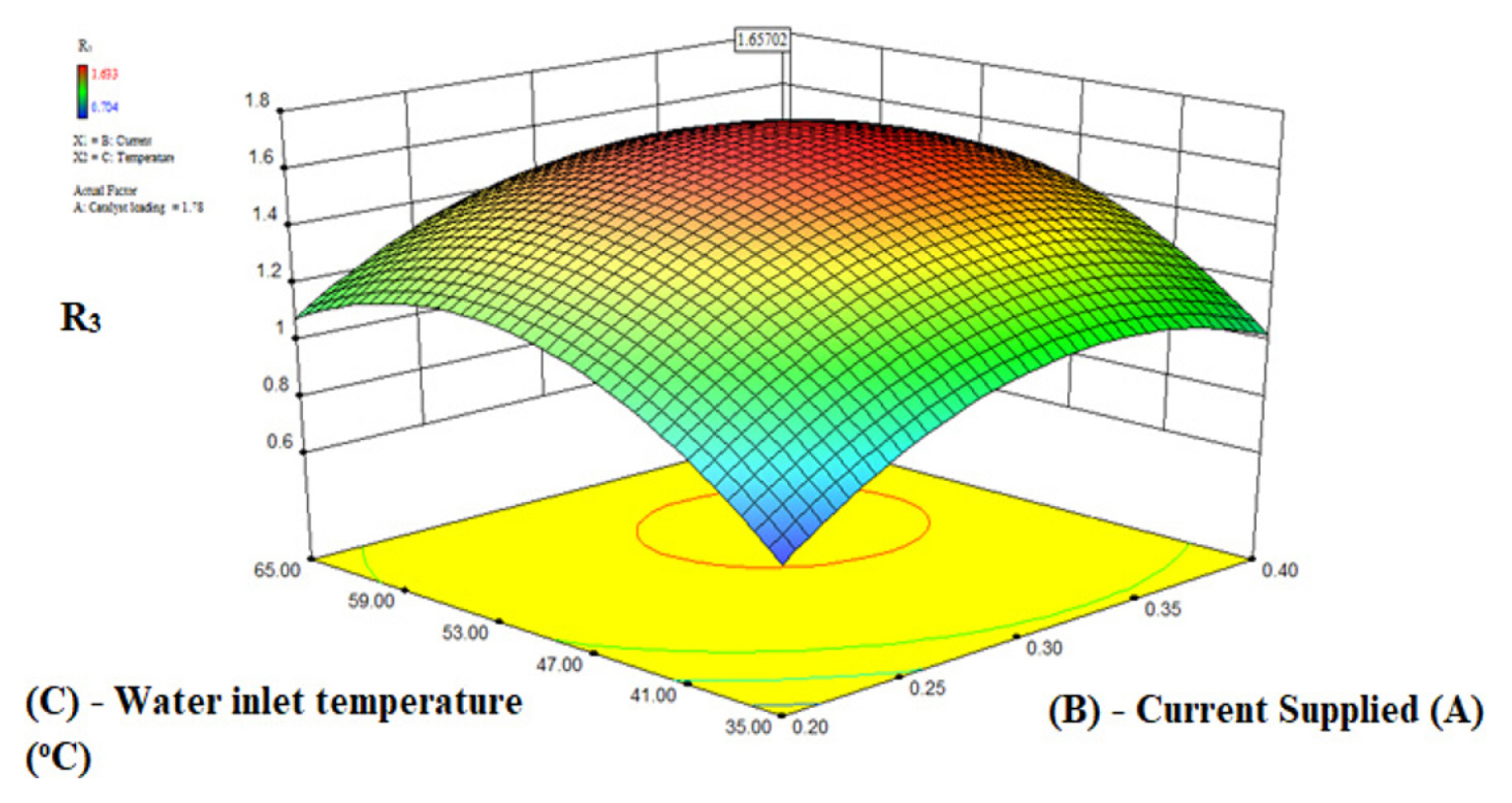
Fig. 6–8 show the interaction between water inlet temperature and applied current and their combined effect on the responses R3, R2, and R1 for a constant O2 electrode catalyst loading (A) of 1.78 mg/cm2. Fig. S9–S11 illustrate the relationship as contour plots while Fig. 6,–8 demonstrate the relationship between the two variables in three-dimension surface plots. Fig. 6 and Fig. S9 shows the effect of input variables current supplied (B) and water inlet temperature (C) on the response R3. The current supply (B) was changed from 0.2 A to 0.4 A as obtained from Fig. 2 and water inlet temperature (C) from 35°C to 65°C at anode loading of 1.78 mg/cm2. It is observed from the Fig. 6 and Fig. S9 that the response R3 increases with the increase in current supplied up to 0.33 A and water inlet temperature up to 54°C to the electrolyzer and then declines therefore the highest R3 value of 1.657 was obtained for the optimum applied current of 0.33 A and optimum water inlet temperature (C) of 54°C. The reason for the trend of R3 with respect to applied current (B) has already been discussed in section 4.2. For the case of other variable water inlet temperature (C) due to the Arrhenius equation at the oxygen electrode a feed at higher temperature improves the activation kinetics of the process, which causes the rising trend till the inlet temperature of 54°C [44,45]. If the temperature further continues to rise the R3 value declines due to the water management issue of Nafion membrane [46] at high temperatures causing irreparable membrane damage [47], which in turn lowers the protons’ transmission rate [48]. At high values of water inlet temperature, the rate of gas diffusion layer corrosion due to oxygen free radical produced during oxygen evolution increases and oxygen bubble production both rise, which leads to an increase in mass transfer impedance as the water transport pathway is effectively blocked due to formation of bubbles [49]. More importantly, it leads to the blocked water transport path between the GDL and membrane interface which increases the proton conduction impedance due to the discontinuous distribution of the water film [50,51].
The effect of applied current (B) and water inlet temperature (C) for R2 is shown in contour plot Fig. 7 and 3D surface plot Fig. S10. It is observed from the Fig. 7 and Fig. S10 that the R2 has increasing trend with the increase in water inlet temperature up to 54°C and further increase in water inlet temperature causes the response R2 to decrease. The trend of R2 for applied current is same as the trend mentioned in section 4.2. Similarly, Fig. 8 shows the contour plot and Fig. S11 shows the 3D surface plot for the effect of applied current (B) and water inlet temperature (C) on the response R1. It is shown in Fig. 8 and Fig. S11 that with the increase in water inlet temperature till 54°C the response R1 increases and then follows a declining trend. For current supplied R1 follows the same trend as discussed in section 4.2. The optimum value current of 0.33 A and optimum water inlet temperature of 54°C were obtained for the maximum value of R2 of 2.567 mL/(min·W) and R1 value of 2.92 mL/min. The reasons for these trends have already been discussed above in this section and section 4.2.
4.4 Combined effect of water inlet temperature and anode electrocatalyst loading
Fig. 9,–11 illustrates the interaction between water inlet temperature and anode electrocatalyst loading along with their combined effect on the responses R3, R2, and R1 for a constant current supply of 0.33 A. Fig. S12–S14 represent the two-dimensional contour plots, while Fig. 9,–11 show the three-dimensional surface plots. Fig. 9 and Fig. S12 shows the effect of input variables anode electrocatalyst loading (A) and water inlet temperature (C) on the response R3. The anode electrocatalyst loading (A) was changed from 0.5 mg/cm2 to 2.5 mg/cm2 and water inlet temperature (C) from 35°C to 65°C at constant current supply of 0.33 A. The trend seen in the case of the water inlet temperature for the response R3, as shown in the contour plot of Fig. S12 and three-dimensional surface plot of Fig. 9, is that it is increasing with the increasing value of both the input parameters, reaches a peak point, and then declines, the maximum R3 value of 1.657 is obtained for the optimal conditions of anode/O2 electrode catalyst loading (A) of 1.78 mg/cm2 and water inlet temperature (C) of 54°C. The reason behind this trend has already been discussed in section 4.2 and 4.3. The corresponding trend of R2 and R1 shown in Fig. 10, Fig. S13, Fig. 11 and Fig. S14 for corresponding input variables of anode electrocatalyst loading and water inlet temperature has already been discussed in section 4.2 and 4.3. The maximum values of R2 and R1 are 2.5625 mL/(min·W) and 2.9207 mL/min obtained at the corresponding values of 1.78 mg/cm2 for anode electrocatalyst loading and 54°C for water inlet temperature.
The input factor values at which the R3 is maximised under the specified O2 electrode catalyst loading (A), current supply (B), and water inlet temperature (C) parameters were 1.78 mg/cm2, 0.33 A, and 54°C, respectively. The estimated maximized R3 value of 1.657 was recorded. The optimal hydrogen production rate (R1) for the given R3 was 2.921 mL/min, while the hydrogen production rate per spent watt (R2) was 2.562 mL/(min·W).
4.5 Verification RSM model
The predicted responses were compared with the experimental ones that were obtained at the same input conditions in order to confirm the model’s results. The comparison between experimental and prediction model is shown in Table S9 and Table S10 where the predicted results of R1 and R2 are compared with the experimental values of R1 and R2 (Table S11) for the optimal conditions of 1.78 mg/cm2 O2 electrode catalyst loading, 0.33 A current supplied and water inlet temperature of 54°C and a random input factor conditions were used for verifying the predicted and experimental responses (Table S12) where the factors were 1.2 mg/cm2 O2 electrode catalyst loading, 0.24 A current supplied and water inlet temperature of 45°C is shown in Table S9 and Table S10. When the values of both the responses were compared for the optimum conditions, the error obtained was 1.47% for R1 and 3.07% for R2 while for the random experimental condition the error was 1.52% for R1 and 3.85% for R2. Thus, the responses predicted by the developed quadratic model were consistent and noteworthy.
This emphasis of model on maximizing operational parameters rather than accounting for degradation effects may be one of its drawbacks. It is also difficult to forecast how long an electrolytic cell will last in usage due to its stability issues. Since the faradic efficiency of electrolytic cell may be impacted by changes in input conditions over time, the impact of dynamic conditions on electrolytic cell performance was not taken into account. It should also be noted that for PEMEC stack more factors and complications would need to be included in order to create an RSM model for this scenario. The major factor which could be taken into consideration is the distribution of power among the stacks as this is the primary issue in the present scenario. The Daisy chain and conventional power allocation systems are the two categories of power allocation strategies. In a traditional stack, input power is distributed equally throughout the stack members, however in a daisy chain, individual cells are activated one at a time, with the preceding electrolyser achieving full power before initiating the subsequent one, and so on. When compared to daisy chain strategies, the conventional allocation strategy typically performs better in the middle and high-power ranges, however its performance in the low power range is below satisfactory. This will complicate the system because, in the case of the conventional allocation strategy, any power fluctuations will affect every electrolyser [52]. Frequent start-stop switching is another issue with the stack that will reduce its efficiency and raise serious safety concerns by allowing hydrogen to build up at the anode and pass through the membrane to the cathode. Additionally, for an electrolyser in a typical technique, the power must be instantly increased from zero to the assigned value, which is challenging to accomplish in practical situation. Additionally, there are many designs that is considered while designing the stacks, including series, parallel, seriesparallel, and cascade architectures, which influence the electrolytic cell efficiency as each architecture require different power allocation strategies. Furthermore, if we take into account the degradation impacts, voltage degradation happens more seriously for the single-stack that is allocated earlier, resulting in longer running times for that single-stack and inconsistent performance. The voltage degradation state of every PEMEC single cell must be considered in the power allocation sequence. Prioritizing the cell with the least deterioration should always come first when implementing the PEMEC stack. However, when the stack needs to be terminated, the most degraded single cell or stack ought to be chosen [53]. Furthermore, the presence of cooling channels in PEMEC stack, which are used to optimize the stack’s temperature, may be important in determining the performance of stack because heat generated in PEMECs is greater than the heat demand by the cell. As a result, the coolant flow rate is another parameter that must be taken into account when performing DOE because it can affect the stack’s temperature uniformity, which in turn affects the stack’s performance [54]. Reactant starvation should also be taken into account in the event of a PEMEC stack, as an abrupt increase in current density can result in an abrupt increase in the rate of electrochemical reactions. If the anode side reactant supply is insufficient, this can easily lead to oxidation of the anode electrocatalyst and irreversible damage to the PEMEC stack [55].
5. Conclusions
The BBD RSM tool was used to optimize the input factors of O2 electrode electrocatalyst loading (A), current supplied (B) and water inlet temperature (C) for the maximum hydrogen production rate (R1) and maximum hydrogen production rate per unit watt consumption (R2) for the developed proton exchange membrane electrolysis cell. The independent variables used for developing the model have considerable impact on the responses which was indicated by the F and P values obtained from ANOVA analysis. For both the responses R1 and R2, current supplied (B) has the most impact followed by O2 electrode/anode electrocatalyst loading (A) and water inlet temperature (C) for R1. Whereas water inlet temperature (C) followed by O2 electrode/anode electrocatalyst loading (A) for R2. The optimum conditions where both hydrogen production rate (R1) and hydrogen production rate per unit watt consumption (R2) were maximized were O2 electrode electrocatalyst loading of 1.78 mg/cm2, current supplied of 0.33 A and water inlet temperature of 54°C. The predicted value of R1 and R2 from the quadratic model were 2.921 mL/min and 2.562 mL/(min·W) with very negligible error % between these prediction and experimental values of 1.47% and 3.08%, respectively. Conclusively, the current investigation underscores the significance of utilizing RSM for the optimization of operational parameters. This approach proves instrumental in attaining elevated cell performance by identifying optimal parameter values, thereby streamlining the process, economizing time, and advocating for a limited number of experimental trials while achieving the highest attainable PEMEC performance.