1. Introduction
Quaternary ammonium (Quat) tetrafluoroborate salts are typically employed as electrolyte salts for electrochemical double-layer capacitors (EDLCs) owing to their wide potential window capable of supporting 3 V operations. The smallest Quat salt for EDLCs is tetramethylammonium tetrafluoroborate, although its low solubility allows only limited applications [1]. The second smallest salt is trimethylethylammonium tetrafluoroborate, which is suitable for high-energy EDLCs owing to its small cation [2]. Since the BF4− anion is smaller than any Quat cation, the capacitance of EDLCs is inversely proportional to the cation size [3]. The size of protic ammonium ions is significantly smaller than that of Quat ions; therefore, the former appear as very attractive tools to increase EDLC capacitance. However, protic ammonium salts (PASs) are electrochemically less durable than Quat salts because of the presence of protons on their cations. Therefore, PASs have not been considered for application in EDLCs, and their properties have not been thoroughly investigated [4,5] Recently, however, PASs have attracted some interest as a new group of materials for use in EDLCs and lithium ion batteries [6].
Since PASs are a subfamily of ionic liquids (protic ionic liquids, PILs), these salts can be used in EDLCs without other solvents. The addition of solvents narrows the potential window of PILs and facilitates their electrolysis regardless of the type of solvent [7–9]. The discharge voltage of EDLCs with PASs in water is limited to 1 V, which is similar to that of EDLCs with sulfuric acid solutions [10,11]. Even if PASs are dried well, they retain a small amount of water bound by hydrogen bonds [9]. Dried PILs provide discharge voltages ranging from 1.5 V [5,12] to 2.5 V [9,13], depending on the amount of residual water. Various acid solutions, such as H2SO4, H3PO4 and HClO4 are proton sources for pseudo-capacitors [11]. PILs can be utilized in pseudo-capacitors [12, 14] with metal oxide-modified carbon [11,15] and graphite electrodes [16]. PASs in non-aqueous solvents can replace sulfuric acid solutions in pseudocapacitors to increase the cell voltage [14].
In this work, we prepared a tertiary ammonium (Tert) salt, trimethylammonium tetrafluoroborate (TriMA BF4), and we investigated its role in EDLCs in the presence of acetonitrile (AN) and g-butyrolactone (GBL). The electrochemical behavior of TriMA BF4 in EDLCs was evaluated to characterize the unique properties of the Tert salt by comparing it to a Quat salt, tetraethylammonium tetrafluoroborate (TEA BF4). TriMA+ is the smallest Tert ion and presents some advantages in comparison with other Tert ions, such as a more efficient ion transport through the pores of activated carbon (AC). In addition, the Tert structure of TriMA+ can serve as a backbone for further chemical modifications of the cation to open the way to further applications in EDLCs and pseudo-capacitors.
2. Experimental
2.1. Chemicals and synthesis procedures
Tetraethylammonium bromide (TEA Br, Tokyo Chemical Industry, Co.) was reacted with tetrafluoroboric acid (HBF4, Alfa Aesar Co., Inc., ca. 50% w/ w aq. soln.) in acetone. The mole ratio between TEA Br and HBF4 was 1:1.1. The solvent and unreacted material were removed using a vacuum pump overnight at 50°C, and a TEA BF4 white powder was obtained. This salt was dissolved in AN, then n-butanol was added to precipitate the salt for recrystallization. TriMA BF4 was synthesized by the following procedure. Trimethylamine (Tokyo Chemical Industry Co., Ltd, ca. 13% in tetrahydrofuran, ca. 2 M) and HBF4 were mixed in an ice bath overnight without any additional solvent. The mole ratio of trimethylamine and HBF4 was 1:1.1. The recrystallization procedure of TriMA BF4 was the same as that of TEA BF4. The final product was obtained by filtration. The salts were dried thoroughly before use. 1H-NMR (Bruker Advance III 400 MHz, DMSO-d6): TEA BF4: d = 1.16 (t, 12H), d = 3.19 (q, 8H); TriMA BF4: d = 2.27 (s, 9H), d = 9.28 (s, 1H).
2.2. Cell preparation
The active material for the EDLC electrode was AC (MSP20, Kansei Coke). The electrode was prepared with AC, carbon black (super-P black, MMM, Belgium), carboxymethylcellulose (Sigma-Aldrich, 1.1% w/w solution), and a styrene butadiene rubber (Zeon, BM-400B) in a weight ratio of 81:12.8:4.2:2 to obtain a slurry. This was applied on an Al current collector using a knife coating device (KP-3000VH, KPAE Co., Ltd) and dried at 80°C in an oven. The electrode was roll-pressed to obtain a thickness of 150 μm. The electrodes were punched out into discs of 14 mm in diameter and dried in a vacuum oven at 60°C for 12 h. Cell tests were performed using a 2032-type coin cell (Hohsen Co.). A cellulose separator (Nippon Godoshi Corp., Φ = 19 mm, thickness = 40 μm) was placed between two electrodes, and the cells were assembled in a dry box. All salts were dissolved in AN anhydrous (Alfa Aesar Co., Inc, > 99.8%, HPLC grade) or GBL (Sigma-Aldrich Co., Ltd), yielding 1.0 M electrolytes. The surface area of AC was determined by the Burnauer-Emmett-Teller method using a gas analyzer (MicrotracBEL Corp., BELSOPR-max), obtaining 2377 m2 g−1. Additional data on the surface measurement are presented in Table S1 (Supporting Information).
2.3. Instruments and measurements
Cell test cycler (WBCS3000, WonATech Co., Ltd) was used for the evaluation of cells. Coin cells were pre-conditioned (formation cycles) for 10 cycles with a constant current of 0.1 A g−1 before the cell tests. Cell tests were performed with constant current mode. The current density for the charge and discharge processes is the same. Seven2Go-pro (Mettler Toledo) was used to measure the conductivity of 1.0 M TriMA BF4 in AN and 1.0M TriMA BF4 in GBL. Conductivity probe was calibrated with a calibration solution of 12.88 mS cm−1 at 25°C. A bottle with a rubber seal is used to insert the conductivity probe, which allows the measurement outside the glove box. Linear Sweep Voltammetry(LSV) was performed using a potentiostat (SP-150, Biologic Science Instruments.). 3-electrode cell(EC-frontier) was used to obtain potential window of the electrolytes for this work. Two identical activated carbon electrodes were placed in the cell as a working and a counter electrode. An Ag/Ag+ reference electrode was inserted to monitor the potential of the working electrode. The filling solution of the reference electrode was 0.1 M tetrabutylammonium perchlorate + 0.01 M AgNO3 in AN. The cells were scanned at a rate of 10 mV s−1 at 25°C.
3. Results and Discussion
The electrochemical potential windows for TEA BF4 and TriMA BF4 in AN (Fig. 1A) and GBL (Fig. 1B) were obtained with the electrodes used as capacitors. Two linear sweep voltammetry (LSV) curves were combined to create a potential window for each electrolyte. New electrodes were used to obtain the first LSV scan. The electrolysis currents in the anodic potential sweep derive from the decomposition of the solvent and the anion; therefore, the comparison between the anodic sweep curves of two different solvents can provide information on the electrochemical activity originated by each solvent. The current levels in the AN solutions in Fig. 1A are much higher than those in the GBL solutions in Fig. 1B: one possible reason for this could lie in the higher conductivities of the former (shown in Table 1), leading to higher oxidation currents. The materials involved in the reduction processes are the cations and solvents. The intensities of the reduction currents generated by the TriMA+ ions were higher than those generated by TEA+ ions in cathodic scans in the same solvents. The protons in TriMA+ generated a higher current than the ethyl cations in TEA+ in the same solvent. The cathodic sweeps for TEA BF4 showed a nearly flat capacitive current curve. The electrolyte decomposition was barely visible in the curve for the TEA BF4 solution until the sweep limit, −2.0 V. In contrast, the electrolysis of the TriMA BF4 solution increased distinctly from −1.0 V, followed by bulk decomposition. Clearly, the proton in TriMA+ is responsible for the more active decomposition than that observed for TEA+.
The oxidation currents for TEA BF4 and TriMA BF4 in the same solvent should be comparable because they are originated by the same materials: the BF4− ion and the solvent. However, the oxidation current from TriMA BF4 was much higher than that from TEA BF4, as shown in in Fig. 1B, although the conductivities of the two solutions were very similar. This difference may derive from the presence of cations or decomposed cation products at the counter electrode, which may diffuse across the membrane. Cases of unidentical oxidation currents from several Quat salts have been reported before, where the solvent and the anion were identical for the investigated salts [17]. The abrupt decrease in current to a noise level is caused by bulk electrolysis.
Starting from the first potential scan, electrolysis products are created and accumulate on the electrode as cycles proceed, forming a passivation layer that increases the electrolysis overpotential [18–20]. The passivation layer allows the expansion of the potential window for long cycles of cell operation. The onset potential of electrolysis changes depending on the way that cells are operated and cell materials selected [21,22].
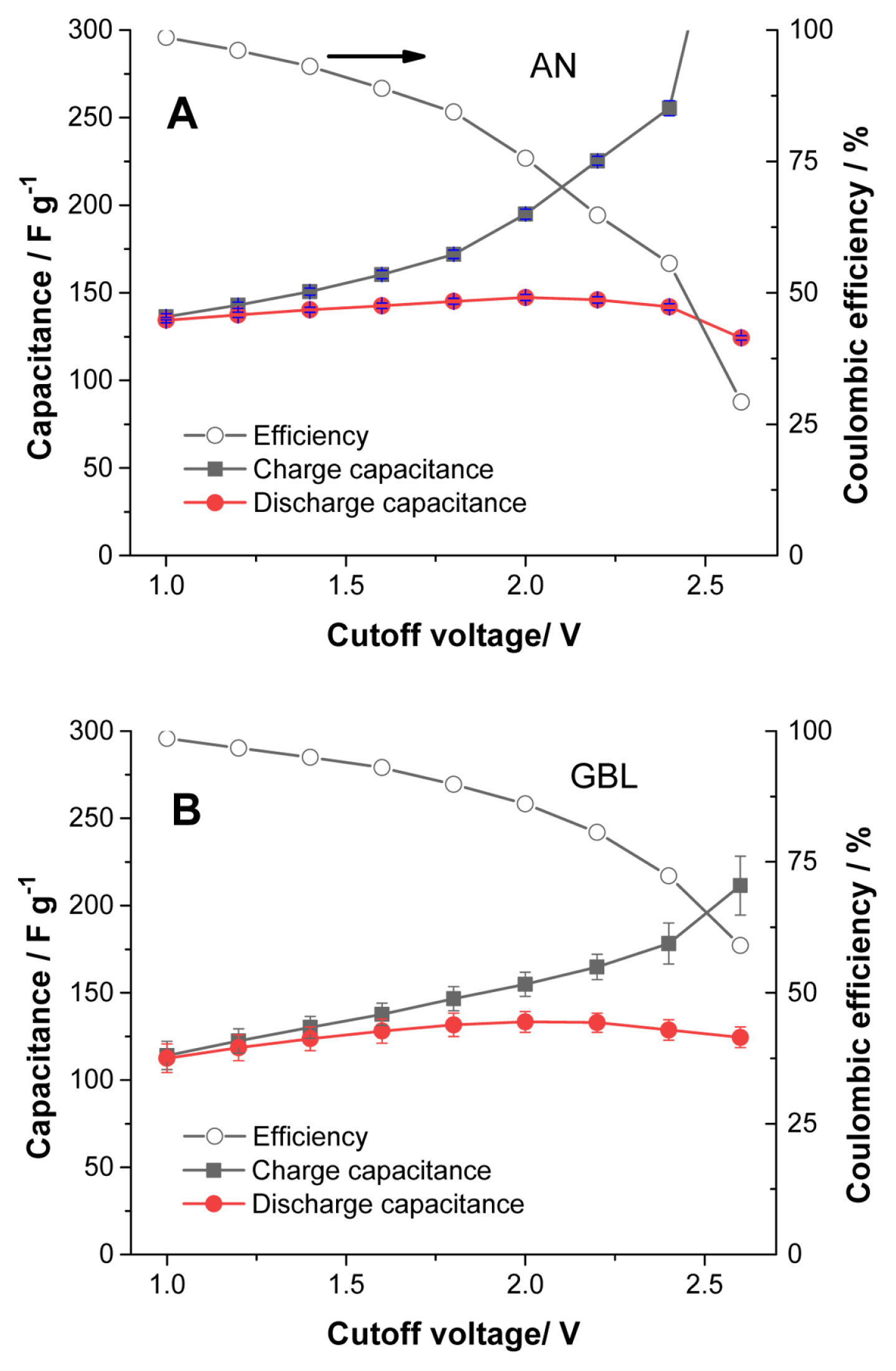
The electrolysis onset potential with the capacitor electrode is not clearly identified in the LSV curves of Figs. 1A and 1B. For this reason, charge and discharge cycles were performed in the galvanostatic mode in fresh cells to better identify the cut-off voltage for the cells with TriMA BF4. Fig. S1 shows a typical measurement in the galvanostatic mode. First, 10 cycles were charged up to 1.0 V, then the cut-off voltage was increased by 0.2 V every three cycles. As the cut-off increased, electrolysis was clearly observed, as indicated by the red arrows in the Fig. S1. Since cells with TEA BF4 can be operated up to 3.0 V, the curves for this electrolyte are not included here for comparison. The capacitance of the cell increases proportionally to the cut-off voltage. The maximum capacitances in both Figs. 2A and 2B were obtained at a 2.0 V cut-off, corresponding to a balance between the decomposition of the electrolytes and the increase in capacity. The balance between electrolysis and discharge capacity can be observed in the coulombic efficiency curves. The coulombic efficiency values of the curves in Fig. 2 are displayed in Fig. 3: a lower coulombic efficiency indicates a higher rate of electrolysis, and the electrolysis appears more active in AN than in GBL. Also, AN provides more capacitance than GBL, as observed in the cathodic scan for TEA BF4 in Figs. 1A and 1B. Since the conductivities of AN solutions are 2.5 times higher than those of GBL solutions, the capacitance is influenced by the ionic conductivity. The difference in viscosity between AN and GBL solutions, shown in Table 1, is nearly four times. Therefore, both the high conductivity and the low viscosity of the AN solutions determine their high capacitance and more active electrolysis.
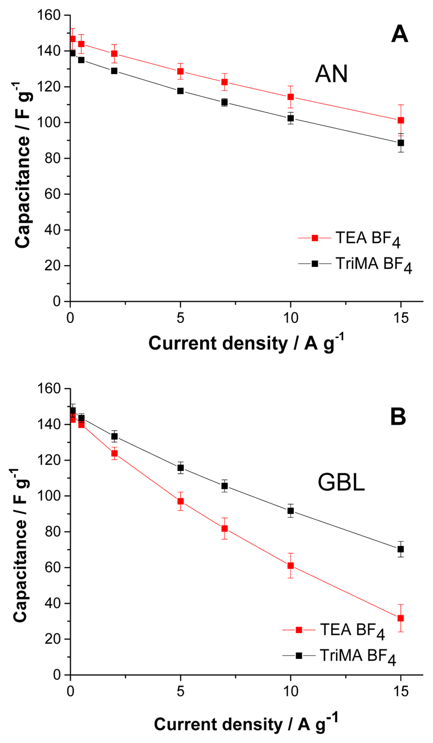
The results in Fig. 3 are obtained from the early cycles of each cell, where the electrolysis is vigorous; this becomes less intense as a passivation layer grows on the surface of the electrode. The efficiency results in Fig. 3 reflect the nature of TriMA BF4 electrolysis in both solvents with fresh electrodes, which can be used as an indirect tool to determine the cut-off voltage for the cells. Among the possible cut-off voltages providing high capacitance values, we selected a value providing a lower electrolysis rate: 1.8 V still affords nearly the same capacitance as 2.0 V, but with a significantly lower rate of decomposition. The capacitance vs. current density (rate capability test, 1.8 V cut-off voltage) curves for the cells with TriMA BF4 and TEA BF4 were compared.
Fig. 4A shows the rate capability tests in AN. Since the electrolysis of TriMA BF4 in AN is very active, the capacitance is lower than that of TEA BF4 throughout the range of current densities. The cells with TriMA BF4 exhibited parallel rate capability curves with those of TEA BF4 despite the active electrolysis, suggesting that the ions in TriMA BF4 are very responsive to current increases. By suppressing the electrolysis with a Tert BF4 salt, we might obtain a substantially better performance than that of TEA BF4 under the same cut-off voltage.
We observed that the electrolysis of TriMA BF4 in GBL was suppressed in comparison with that in AN, as shown in Fig. 3. The coulombic efficiency of the cells at a 1.8 V cut-off voltage in AN was 84.4% (Fig. 3A), while it was 89.8% in GBL (Fig. 3B). In addition, GBL allowed faster ionic movement for TriMA BF4 than for TEA BF4. The conditions of conductivity and viscosity in TriMA BF4 were slightly more advantageous for ion transport than those in TEA BF4. For these reasons, the capacitance values of TriMA BF4 were significantly higher than those of TEA BF4 in the current density range shown in Fig. 4B. The difference in capacitance became larger as the current density increased. Although the electrolysis rate was lowered by replacing AN with GBL, the protons in TriMA BF4 were still vulnerable to electrolysis. Nevertheless, owing to the relatively advantageous values of conductivity and viscosity, TriMA BF4 exhibited a superior rate capability compared to TEA BF4. Fig. S2 shows the coulombic efficiency results of the curves in Fig. 4B, where the conductivity and viscosity compensate the weakness from electrolysis. Except for the lowest current density of 0. 1 A g−1, the efficiencies of TriMA BF4 cells were slightly higher than those of TEA BF4 cells. Electrolysis was the dominant element at low current density, where the cells with TEA BF4 exhibited a higher efficiency; as the current density increased, the conductivity and viscosity became the main elements influencing cell efficiency.
Some electrolysis issues have been observed with TriMA BF4, but it is known that a passivation layer can suppress electrolysis. When cells are operated under a moderate cell voltage, the passivation layer can effectively support long cycles. The durability of our cells was evaluated by performing cycle life tests with TriMA BF4 electrolytes in AN and GBL. The tests were carried out at 1.0 A g−1. Because the cells were cycled at relatively high current densities, to compensate for the high viscosity of the electrolyte, a large number of cycles was required to stabilize the cell capacitance. Up to 3000 cycles, the capacitance values for the two electrolytes nearly converged. The cells with GBL required some time to approach the capacitance level corresponding to a complete wetting of the electrodes. The coulombic efficiency at 3000 cycles was slightly above 100%: the capacity that was not discharged at the previous cycle was added to the next cycle, thereby yielding efficiency values above 100%. After the 3000th cycle, the systems were allowed 3 d of rest and then restarted once the GBL cells were properly wetted. The value of 100% efficiency was achieved after a second process consisting of 3000 cycles with the GBL electrolyte. In contrast, the cells with AN, which did not present issues with wetting, exhibited an efficiency slightly lower than 100% owing to the electrolysis. After the rest period, the capacitance of the GBL cells resulted higher than that of the AN cells: the higher rate of electrolysis in the AN solution was responsible for such a difference. Once the wetting process was complete, the high viscosity and low conductivity of GBL cells were no longer a significant obstacle at the operating current density. Evidently, conductivity and viscosity are properties of bulk solutions, and they play an important role only before completion of the wetting process; after that, the TriMA+ ion can sustain a high current density in the pores of the electrode owing to its small size.
The implementation of a wetting process during cell assembly and formation can reduce wetting time. Cells with the Tert salt electrolyte in both GBL and AN were stable for at least 6000 cycles, owing to the action of the passivation layers. TriMA BF4 in GBL proved especially suitable for moderate current density EDLCs. The stable life cycle with this electrolyte suggests pseudo-capacitive applications at outputs below 1.8 V. Also, TriMA BF4 in GBL can afford high-temperature operation because of the higher boiling point of GBL (204°C) compared to AN (82°C) [23]. GBL is used as a binary solvent for high temperature and high voltage capacitors with ionic liquids [24,25]. The modification of the TriMA+ ion by replacing the methyl moiety with another alkyl group can provide a new structure capable of suppressing electrolysis. In this way, such a modification can expand the cell voltage and allow for the use of AN as the electrolyte solvent.
4. Conclusions
EDLCs with electrolytes based on a Tert salt, TriMA BF4, in AN and GBL solvents achieved a cutoff voltage of 1.8 V. The vulnerable protic salt limited the cell voltage in comparison to EDLCs based on Quat salts; however, this electrolyte provided a voltage two times higher than aqueous H2SO4 electrolytes. The GBL-based electrolyte, which exhibited weaker electrolysis, showed a better cycle life than the AN one. Importantly, the Tert ion TriMA+ ion presents a simple structure that can act as a backbone for structural modification with numerous possible alkyl groups. With the introduction of appropriate alkyl moieties, electrolysis can be further suppressed, and the conductivity and viscosity of the electrolyte can be enhanced using AN as a solvent. In summary, Tert BF4 salts present potential for use in mid-voltage applications, which suggests that their properties lie between those of protic aqueous- and non-aqueous solutions for pseudo-capacitors and EDLCs.