


1. Introduction
Lithium-sulfur batteries have a much higher specific capacity (1,675 mAh/g) and energy density (2,600 Wh/kg) than conventional lithium ion batteries [1-6]. However, lithium sulfur batteries are difficult to commercialize, because the lithium metal used as the anode is prone to dendrite growth and explosiveness. Conventional carbon anodes that are used for rechargeable lithium-ion batteries cannot match the performance of rechargeable lithium-sulfur batteries, since they have low capacities and poor passivation in ether-based electrolytes compared with ester-based electrolytes. Therefore, alternative anodes for high-capacity sulfur cathodes are required. Silicon, which exhibits a very high specific capacity of 4,200 mAh/g (for a stoichiometry of Li4.4Si), is one of the most attractive candidates for use as an anode material in lithium-ion batteries [7-11]. Combining a pre-lithiated silicon anode with a sulfur cathode may promote the utility and stability of lithium-sulfur batteries. However, both the sulfur cathode and the silicon anode have many drawbacks. The main drawback of the sulfur cathode is a rapid capacity fading, due to the generation of lithium polysulfides during cycling [12-14]. Lithium polysulfides, the intermediate products in the sulfur redox reaction, are readily dissolved out into the electrolyte during cycling. They then react directly with the lithium anode to regenerate lower-order polysulfides, which diffuse back to the sulfur cathode to regenerate the higher-order polysulfides again, thus reducing the cyclic efficiency of the lithium-sulfur battery. Silicon used as an anode material is hampered by its large volume expansion (>300%), causing pulverization and the loss of electrical contact, and consequently an early capacity fading. Various approaches to solving these problems have been suggested [15-18]. Also, silicon anode needs to be prelithiated for combination of sulfur cathode without lithium source. Various methods for pre-lithiation have been reported, such as chemical reaction [19] and hydrothermal treatment [20]. However, these methods are expensive and complexity of synthesis process for pre-lithiation. Y. Cui et.al suggested a cheaper and simpler method for prelithiating a silicon anode by a self-discharge mechanism (direct contact method). Lithium source for silicon anode is used cheap lithium metal foil [21].
In this work, we demonstrate an advanced lithium metal free, pre-lithiated, silicon-sulfur battery. In particular, the carbon mesh we reported previously [19] was inserted between the sulfur cathode and the separator in order to maximize the performance by capturing the dissolved polysulfide in sulfur cathode. The sulfur cathode with carbon mesh inhibited polysulfide dissolution into the electrolyte, and thus enhanced the cyclic efficiency of the lithium-sulfur battery. In addition, to build on our previous success, we improved the silicon anode by adding a carbon coating to the silicon surface. With this treatment, both the electronic and lithium-ionic conductivity of silicon anodes was improved markedly. Prior to use in the silicon-sulfur batteries, the silicon anodes were lithiated by direct contact with lithium foil in a 1M LiTFSI solution with 1,2-dimethoxyethane (DME) and 1,3-dioxolane (DOL) at a volume ratio of 1:1.
2. Experimental Section
LiN(CF3SO2)2 (LiTFSI) (Aldrich, 99%) lithium salt was used without further pretreatment. The electrolyte used was a solution of 1M LiTFSI salt in a binary solvent mixture of DME and DOL at a volume ratio of 1:1. Nano-sized silicon powder (Alfa Aesar, 30 nm) was heat treated at 700℃ under an argon and 10 mol % propylene mixed-gas flow for 10 h. After this, the carbon-coated silicon powder was allowed to cool naturally to room temperature. The anode used carbon-coated silicon as the active material (80 wt %), denka carbon black (10 wt %) as the conductive material, and a sodium carboxymethyl cellulose (1 wt % in water) and styrene butadiene rubber (40 wt % in water, Zeon) mixture as the binder. The area of silicon anode was 2.009 cm2 and the mass loading density was 1.0 mg/cm2. The thickness of silicon anode was 30 µm. The carbon-coated silicon anodes were lithiated by direct contact with lithium foil for several minutes in the same electrolyte. The silicon anode for half-cell was assembled with pre-lithiated silicon, Li metal and microporous Celgard separator (Celgard 2400) using CR2032 coin type cell. The cyclic test of the silicon half-cell was carried out between 0.01 and 1.0 V in the galvanostatic mode using Maccor cycle system (S 4000 series). Acetylene black mesh was prepared by the thermal decomposition of acetylene black and polytetrafluoroethylene (PTFE), and inserted between the sulfur cathode and the separator [19]. The weight of acetylene black mesh was 0.016 g/cm2 and thickness was about 100 µm. The sulfur cathode consisted of 60 wt % elemental sulfur as the active material (Aldrich, 98%), 30 wt % Super P carbon black as the conductive material, and a 10 wt % polyvinylidene fluoride solution as the binder(loading density of sulfur : 1 mg/cm2). This sulfur cathode was assembled with the above lithiated silicon anode using CR2032 coin cells (N/P ratio in the full cell: 1.5) in a dry room (dew point: −80℃) and a microporous polypropylene separator (Celgard 2400). The crystal structure of the electrode active material was analyzed by X-ray diffraction (XRD, Rigaku D/MAX-2500V) and dispersive Raman spectroscopy (Nicolet Almega XR dispersive Raman Spectrometer, Thermo Scientific Corp.). The morphology of the electrodes was examined by scanning electron microscopy (SEM, Hitachi 4300) and transmission electron microscopy (TEM, Tecnai F20G2) with high resolution. The cyclic properties of the cells were obtained in the galvanostatic mode in the voltage range of 1.0 to 2.8 V vs Li/Li+ using a Maccor cycle system (S 4000 series).
3. Results and Discussion
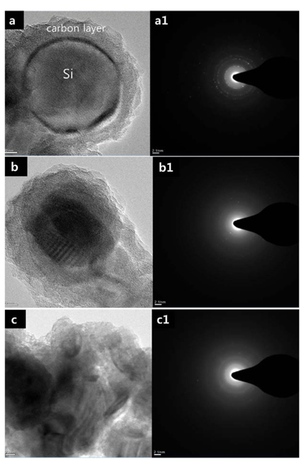
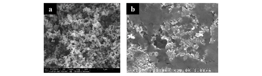
Fig. 1 shows the XRD patterns of the silicon anodes lithiated by direct contact with lithium foil without a separator in a 1M LiTFSI electrolyte solution. The lithiated silicon anodes retain the crystal structure even after lithiation and show the peaks at around 33°, indicating a LixSi alloy. LixSi peak intensity at around 33° decreased with increasing the lithiation time, which indicates that the silicon anode is being amorphous. These XRD results were also confirmed by the Raman spectra, as shown in Fig. 2. The peaks at around 520 cm−1, which are characteristic of crystalline silicon, are detected in the lithiated Si anodes. The silicon anode lihiated for 60 min shows a lower peak intensity than that for 30 min, indicating that the crystalline phase of silicon is gradually changed into amorphous phase, in consistent with XRD results. Fig. 3 shows the SEM images on the surface morphology of the Si anodes before (Fig. 3a) and after (Figs. 3b and 3c) lithiation. The images indicate that the surface morphology of the lithiated Si anodes was well maintained after lithiation, as shown by a comparison of Figs. 3b and 3c with Fig. 3a. The average diameter of the lithiated Si powder particles slightly increases from ~30 nm to ~40 nm after lithiation process by volume expansion due to the lithium insertion. TEM was used to further study the inner structural changes in the silicon anodes after lithiation. The pristine silicon nanopowders had smooth surfaces (Fig. 4a) and were totally crystalline, which is identified with the white spots in the electron diffraction pattern as shown in the insert of Fig. 4a. Even though the thickness of carbon layer was not uniform, it was estimated to be approximately 10 nm on an average. Even after 30 and 60 min lithiation contact times, the core part of silicon nanopowder was still in the crystalline phase unlike the shell part (Figs. 4b and 4c).
Fig. 1.
XRD patterns of lithiated silicon anodes (a: pristine, after a contact time of b: 30 min, and c: 60 min).
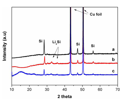
Fig. 2.
Raman spectra of lithiated silicon anodes(a: pristine, after a contact time of b: 30 min, and c: 60 min).
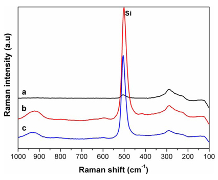
Fig. 3.
SEM images of lithiated silicon anodes(a: pristine, after b: 30 min and c: 60 min contact time).
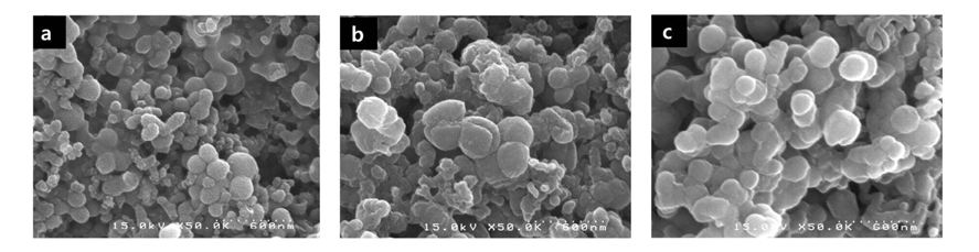
Fig. 4.
TEM images of lithiated silicon anodes (a: pristine, after b: 30 min and c: 60 min contact time).
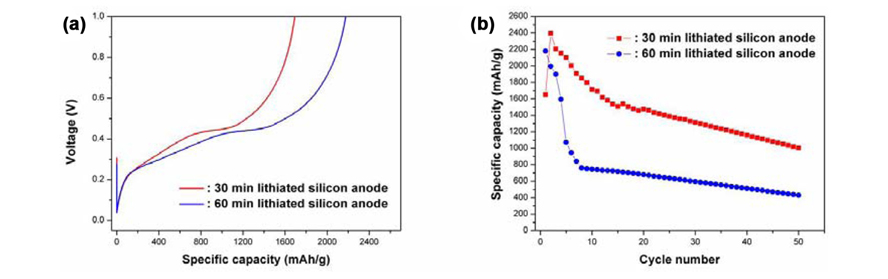
In order to investigate the electrochemical behavior of prelithiated silicon anodes, galvanostatic test was carried out using a battery tester from 0.002-1.0 V versus Li+/Li. Fig. 5a shows the degree of lithiation of the silicon material as a function of the contact time in the ether-based electrolyte. The open circuit voltages (OCV) of silicon anodes prelithiated for 30min and 60min were 0.29 and 0.26 V. These lithiated silicon anodes were then de-lithiated to 1 V vs Li/Li+ by the galvanostatic method at 0.1 C (400 mA/g based on the carbon-coated silicon mass). As shown in Fig. 5a, the specific capacity of the lithiated silicon anode with 30 min of contact time was about 1,700 mAh/g, based on the carbon-coated silicon mass. With 60 min of contact time, the lithiation might saturate, and the specific capacity was about 2,200 mAh/g. Cycle performances with two anode samples is shown in Fig. 5b. The specific capacities of lithiated silicon anodes with 30 min and 60min of contact time were 429 and 1004 mAh/g after 50 cycles, respectively. It is interesting to note here that the 30 min lithiated silicon anode exhibited better capacity than the 60 min lithiated silicon anode. Although a longer lithiation time increases the amount of lithium in the silicon powder, it results in poor cyclability, as reported previously [15]. On the other hand, even though a 30 min lithiated silicon anode has a smaller lithiation than 60 min lithiated sample, this contact time is good enough to meet the requirement of the theoretical capacity of the sulfur cathode in the full cell. Therefore, we choose the 30 min as lithiation time of silicon nanopowder for the full cell study.
Fig. 5.
Electrochemical performances of lithiated silicon anode half cells. (a) First charge voltage profiles and (b) cycle performances of lithiated silicon anodes at 0.1 C.
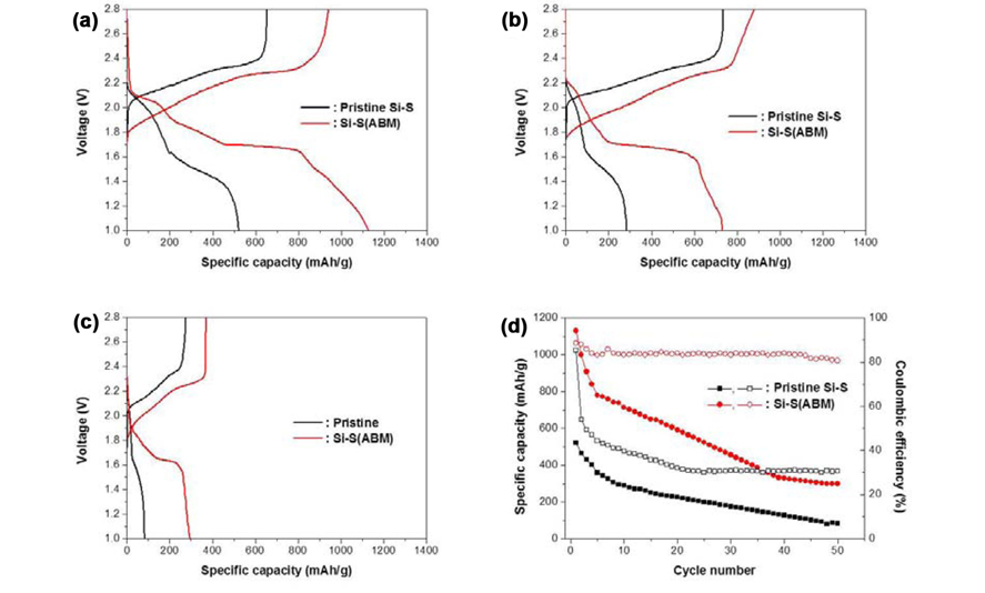
The gavanostatic tests were performed to investigate the performances of lithiated silicon/sulfur full-cell. Lithium polysulfides, which are intermediate products generated during the discharge process, can be dissolved in the electrolyte and diffuse into the anode surface. These species easily react with the anode to generate low-order lithium polysulfides, which then diffuse back to the sulfur cathode to generate higher-order lithium polysulfides again, thus creating a shuttle reaction [12-14]. This shuttle reaction reduces the coulombic efficiency of lithium-sulfur batteries and thus limits the utility of the sulfur cathode during the cycling. In our previous work, a new type of approach to solving the polysulfide dissolution problem in the Li-S battery, the insertion of acetylene black mesh between the cathode and the separator, was presented [19]. This approach was very effective in capturing the polysulfides during the charge-discharge process in the electrolyte without using a LiNO3 additive. With this reason, we inserted the carbon mesh between the sulfur cathode and the separator. Fig. 6 represents the morphology of acetylene black mesh (ABM) with SEM. The acetylene black carbon was in the size of about 100 µm. The ABM made in acetylene black carbon consists of macro pores ranged from a few hundred nanometers to a few micrometers. Fig. 7 represents the voltage profiles and the cycle performance of lithiated silicon-sulfur full cell with or without carbon mesh during the cycling in a 1M LiTFSI electrolyte without LiNO3 added as a shuttle inhibitor. We denoted the silicon-sulfur full cell with no carbon mesh and carbon mesh by Pristine Si-S and Si-S(ABM). The discharge/charge voltage curves of first, 10th, 50th cycles of the lithiated silicon-sulfur batteries are shown in Fig. 7. In general, there are two discharge voltage plateaus, corresponding to the reduction of elemental sulfur to high-order lithium polysulfide at about 2.2 V and to low-order lithium polysulfide at about 1.7 V. Pristine Si-S showed 521 mAh/g (85.2% of coulombic efficiency) at initial discharge, 293 mAh/g (39.6% of coulombic efficiency) at 10th discharge, and 82 mAh/g (30.5% of coulombic efficiency) after 50 cycles. In the case of Si-S(ABM), capacity and coulombic efficiency increase was observed that 1129 mAh/g(88.5%), 736 mAh/g(83.6%) at initial and 10th discharge, and 297 mAh/g(80.6%) after 50 cycles were obtained. Fig. 6d demonstrates the cycle performance of the pristine Si-S and the Si-S(ABM). The Si-S(ABM) showed higher capacity and good coulombic efficiency in comparison with the pristine Si-S. The coulombic efficiency of the Si-S(ABM) was about 88% at the first cycle, and remained at 80% after 50 cycles, while coulombic efficiency of the pristine Si-S was about 85% at the first cycle, and remained at 30% after 50 cycles.
4. Conclusions
In this study, we demonstrated the silicon anodes, lithiated by direct contact with lithium foil in an ether-based electrolyte. It was revealed that the carbon-coated silicon anode was lithiated up to ~40% of its theoretical capacity after 30 min of contact time. The reversible specific capacity was about 297 mAh/g (80.6% of coulombic efficiency) after 50 cycles in the lithiated silicon-sulfur cells with carbon mesh at 0.2 C, without a lithium dendrite problem. We therefore strongly suggest that this novel approach to employ both the lithiated silicon anodes and the carbon mesh insertion layer can address the safety problems associated with the use of lithium metal anodes and the serious deterioration of cycle performance due to the polysulfide dissolution in the lithium sulfur batteries.


