1. Introduction
Recently, high-energy lithium-ion batteries (LIBs) have attracted significant interest in electric vehicles (EVs) and hybrid electric vehicles (HEVs) applications [1ŌĆō3]. As a result, many research groups have tried to develop and engineer the creation of low-cost, higher-energy-density LIBs [4,5]. Layered LiNixCoyMnzO2 (NCM, x+y+z=1) and LiNixCoyŌłÆAlzO2 (NCA, x+y+z=1) cathode materials have already replaced LiCoO2 (LCO) in the LIBs for the EV market, recently [6]. Among many cathode candidates, three-component layered oxide LiNixCoyMnzO2 (NCM, x+y+z=1) has received enormous attention because of their higher specific capacity, and cost-effectiveness [7]. Therefore, it is essential to find an appropriate method to prepare a high and stable performance LiNixCoyMnzO2 [8]. As part of these efforts, the LiNixCoyMnzO2 was prepared via a conventional solid-state reaction [9,10]. Later, various methods have been considered for preparing the active materials of LIB cathodes, such as co-precipitation, hydrothermal, emulsion-drying, spray pyrolysis, sol-gel and mechanochemical methods. Among them, co-precipitation is a well-known method for preparing the precursor for cathode materials. Using the co-precipitation method, NixCoyMnz(OH)2 (NCM, x+y+z=1) powders are fabricated by hydroxide precursors. However, this process is complicated, time-consuming, requires continuous washing, long drying time, and difficult to control the particle size. In addition, the co-precipitation process consumes strong basic solution for the preparation of NCM precursor, that lead towards environmental pollution [11,12].
To resolve these issues, herein we introduced and optimized the facile spray-drying process to prepare the precursor materials for LIB cathode electrode. Generally, spray-drying is a well-known method in chemical, food, ceramics, fertilizers, organic chemicals, pharmaceuticals, and biological agents industries [13,14]. Recently, this method has been used to obtain a special place in nanoscience and nanotechnology, intending to realize evaporation-driven self-assembly of nanoparticles at various physicochemical and thermos-dynamical conditions [15ŌĆō17]. During the drying process of micrometric droplets containing colloidal nanoparticles, droplet size shrinkage is primarily driven by simple evaporation, which is the main advantage of this method. The main advantage of spray-drying method is a one-step process which consists of four processes: step 1) preparation of the spraying solution, step 2) spraying the solution, step 3) formation of dry particles, and step 4) collection of the dry powder [13,18]. A spray dryer transforms a fluid into dry powder by atomization in a hot drying gas stream [19]. The main factor affecting the overall performance of the final product can be tuned by several key factors such as feed flow rate, drying air flow rate, temperature, type of liquid feed, and equipment design [20]. For example, high flow rates, high concentrations of the liquid feed, and large nozzle diameter generate large-sized particles. Conversely, opposite situations such as low surface tension, high spray pressure, and smaller nozzle diameter, renders smaller particles [18,21]. This technique can be dissolved or suspended in a polymer/organic solvent environment and aerosolized through a nozzle to generate micro-droplets. The solvent used in this process can be quickly evaporated by passing through the dryer chamber [13]. ThatŌĆÖs why the spray-drying process is rapid, continuous, and cost-effective spray-drying process is an excellent way to fabricate the dry powder from a fluid material via atomization through an atomizer into a hot drying gas medium [18,22]. In addition, atomization can provide a flexible, controllable, and scalable approach for particle engineering. By replacing the current co-precipitation method with the spray-drying process to synthesize precursors, can prevent not only environmental damage but also gain economic benefits.
In this study, Ni0.91Co0.06Mn0.03CO3 precursor powders were synthesized by a simple spray-drying process and used as starting material to produce LiNi0.91Co0.06Mn0.03O2 active material for the cathode electrode in lithium-ion batteries.
2. Experimental
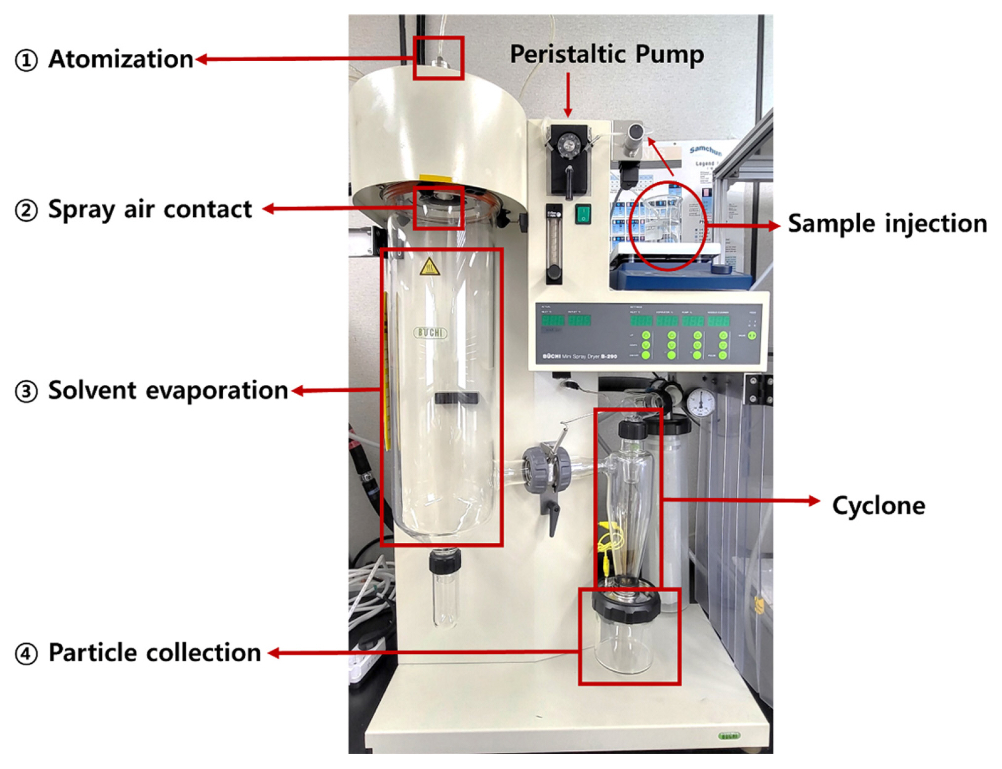
The Ni0.91Co0.06Mn0.03CO3 precursor was prepared using a stoichiometric amount of Nickel (II) carbonate (NiCO3, Samchun Chemical Co., Ltd., purity 100%), Cobalt (II) carbonate (CoCO3, Co 43ŌĆō47%, Sigma-Aldrich), and Manganese (II) carbonate (MnCO3, >99.9% trace metals, Sigma-Aldrich). Firstly, the carbonate salts in a molar ratio of 0.91:0.06:0.03 (Ni2+:Co2+:Mn2+) were dissolved in deionized water. And then, organic acid (citric acid, >99.5%, Sigma-Aldrich) was slowly added to the solution, followed by stirring for 5 hours. To reduce the hygroscopicity of powder and achieve good recoveries, citric acid was introduced in this study [23]. Further, these precursor powders were completely dissolved into deionized water towards the spray-drying process (BUCHI B-290, Switzerland, Fig. 1).
After the spray-drying process under various conditions, the clear solution was obtained and mixed via LiOH┬ĘH2O (5 wt% excess, >98.0%, Sigma-Aldrich) by hand-grinding. The sintering process consisted of two steps to obtain the active material: the first (480┬░C for 5 h) and the second (780┬░C/800┬░C for 15 h) under an oxygen atmosphere. To study the effect of sintering temperatures, the powders were sintered at 780┬░C and 800┬░C. The cathode electrode was prepared by mixing 96 wt% active material, 2 wt% polyvinylidene fluoride (PVDF, Mw 602,000, Solvay Chemicals), and 2 wt% super P in N-methyl pyrrolidinone (NMP, 99.5%, Sigma-Aldrich), which is similar to our previous work [24]. The obtained slurry was coated on aluminum (Al) foil once. Afterward, the electrode was dried at 100┬░C in a vacuum oven for 10 hours to evaporate the residual N-methyl-2-pyrrolidone solvent. The loading density of electrodes was around 14.5 ┬▒ 0.5 mg/cm2. After that, the coin cells (2032 type) were fabricated with cathode and lithium metal discs as anode components. A polyethylene (PE) film was used as a separator, which is the same as our previous work, and 1.0 M LiPF6 ethylene carbonate (EC), dimethyl carbonate (DMC), and ethyl methyl carbonate (EMC) (1:1:1, v/v/v) was used as an electrolyte [24,25].
In the analysis part, surface morphologies of the Ni0.91Co0.06Mn0.03CO3 precursors and LiNi0.91 Co0.06Mn0.03O2 cathode active materials were studied by FE-SEM (Field Emission Scanning Electron Microscopy, Hitachi S-4800). Physicochemical characteristics of the Ni0.91Co0.06Mn0.03CO3 precursors and LiNi0.91Co0.06Mn0.03O2 cathode active materials were examined via Thermogravimetric Analysis (TGA, SDT Q600, TA Instruments). To confirm the element ratios of the Ni, Co and Mn, EDS (Energy dispersive X-ray) was conducted. The crystalline structure of the NCM powders was characterized by XRD (X-ray diffraction, X-pert PRO MPD, Philips) via Cu K╬▒ radiation at 2╬Ė = 10ŌĆō90┬░. The electrochemical properties were determined by electrochemical equipment (TOSCAT-3100, Toyo system). For assembling the coin cell and testing of charge-discharge cycling, density values of 3.33ŌĆō3.45 g/cm2 for LiNi0.91Co0.06Mn0.03O2 cathode active materials were applied. The galvanostatic chargeŌĆōdischarge test of the NCM electrodes measured in a voltage range of 3.0ŌĆō4.3 V at 25┬░C.
3. Results and Discussion
For the preparation of Ni0.91Co0.06Mn0.03CO3 precursor, a systematic optimization of vital factors such as i) atomizing air spray flow rate, ii) feed flow rate (pump feeding rate), and iii) air flow rate (aspirator flow) has been carried out using a spray dryer (Fig. 1). As summarized in Table 1, we explored the nine different conditions to optimize the fabrication process of Ni0.91Co0.06Mn0.03CO3 precursor upon three main parameters. Here, equation (1) was adopted to see the production yield of the precursor [26].
Where Wrecovered is weight of recovered spray-dried powder and Wtotal is the total amount of dry solids in the initial feed solution. From this equation, we found that the yield of dry powder varies widely from 11 to 75%, depending on each condition. For example, the lowest yield was obtained from condition 1, otherwise, the highest yield was obtained from condition 6, showing 75%. Except for condition 6, we obtained low yields (less than 60% of production yield) due to the difficulties in collecting samples, especially for small and light particles produced by the aspirator [27]. However, the yields were acceptable in the lab-scale range.
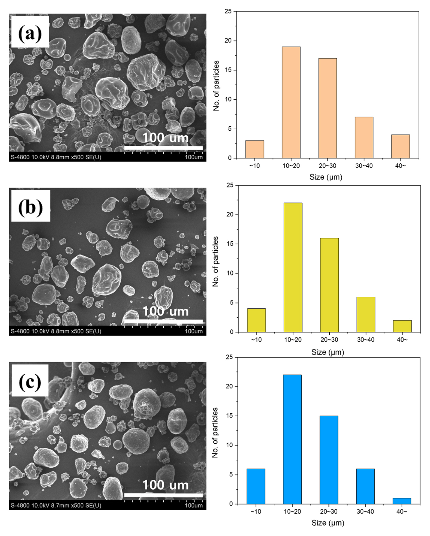
And then, we explore the effect of i) atomizing air spray flow rate on the precursor formation as a critical parameter of the spray-drying process. Through the spray-drying process, we obtained the Ni0.91Co0.06Mn0.03CO3 powder as a NCM precursor. In order to characterize the precursor, SEM and X-ray diffraction experiments were employed. Fig. 2 shows the morphology of the spray-dried Ni0.91Co0.06Mn0.03CO3 precursor and their respective size distribution graph depending upon the atomizing air spray flow rate (rotameter).
From the SEM images and size distribution graphs, we confirm that the decrease in the Ni0.91Co0.06 Mn0.03CO3 precursor particle size is according to the increase in the atomizing air spray flow rate (L/h) ((a) 357 L/h, (b) 601 L/h, and (c) 742 L/h). Unimodal particle size distributions were observed from all cases, having 19.4 ┬▒ 8.44 to 23.3 ┬▒ 10.01 ╬╝m of average particle diameters. Here, the larger mean particle size (23.3 ┬▒ 10.01 ╬╝m) was obtained in the case of 357 L/h of air spray flow rate due to the bigger size of the spray drops. On the other hand, the smallest solid particles (19.4 ┬▒ 8.44 ╬╝m) were obtained at 742 L/h of atomizing air spray flow rate [28]. In addition, an increase in the atomizing air spray flow rate leads to the modification in the precursor shape from an irregular surface to a spherical shape with a smooth surface, as shown in Fig. 2(aŌĆōc) [29].
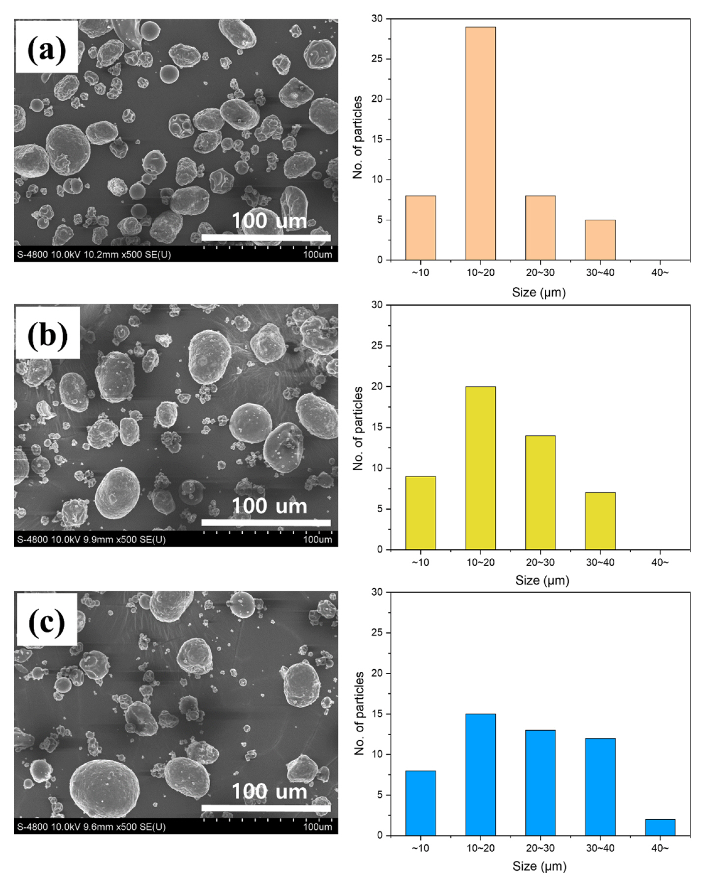
Later, we altered another factor, i.e. ii) feed flow rate of pump. The influence of the ŌĆśfeed flow rateŌĆÖ is also summarized in Fig. 3, including the SEM images for different feed flow rate from 1.5 to 4.5 mL/min. As shown in Fig. 3(a), the smallest particle distribution (around 10ŌĆō20 ╬╝m, mostly) of Ni0.91Co0.06 Mn0.03CO3 precursor was observed from the lowest feed flow rates (1.5 mL/min) case. On the other hand, at the highest feed flow rate condition (4.5 mL/min), we observed large particle size contributions (22.3 ┬▒ 10.66 ╬╝m) which is due to the large liquid dispersity that leads to the large particle size distribution. Therefore, from Fig. 2 and Fig. 3, we conclude that two factors (atomizing air spray flow rate and feed flow rate) can mainly affect the total precursor particle droplet size and morphology.
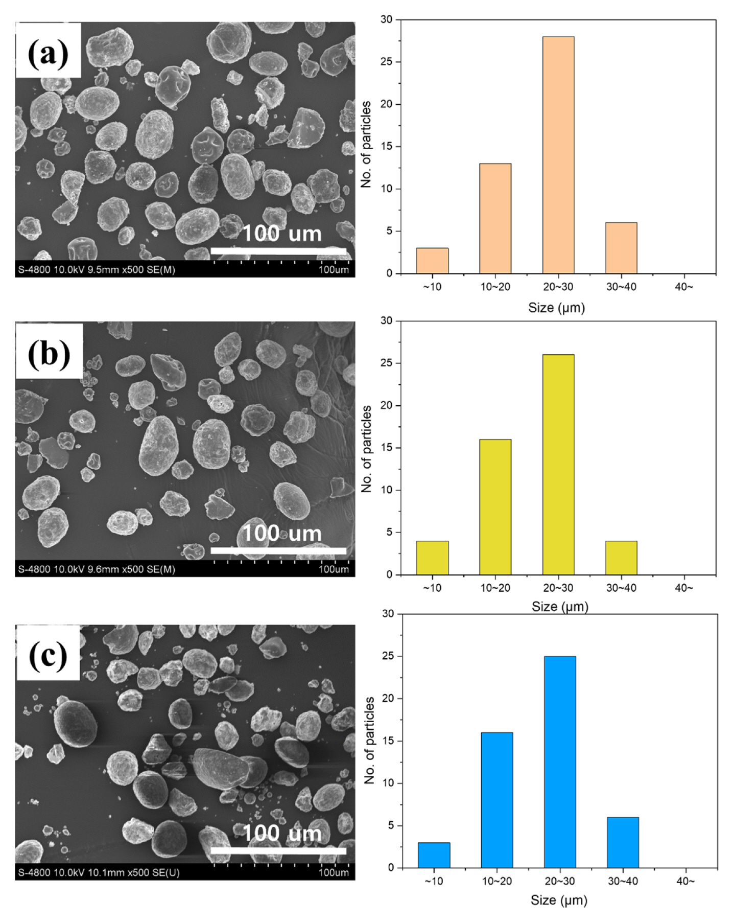
And then, we explore the effect of iii) drying air flow rate on particle size distribution [29], because it also can affect the total performance of the lithium-ion battery. In summary, the drying air flow rate (aspirator flow) value of (a) 20 m3/h led to forming particles with better morphological characteristics that gave a good shape for those obtained with 35 m3/h. Also, total device yield (See Table 1) and Ni0.91 Co0.06Mn0.03CO3 precursor size (Fig. 4) were scarcely influenced by the drying air flow rate (aspirator flow). Considering various parameters such as precursor droplet size, morphology, and yield, we can conclude that the optimal spray-drying operating conditions with good electrochemical characteristics can be seen from the ŌĆścondition 7ŌĆÖ case, as validated in Table 1.
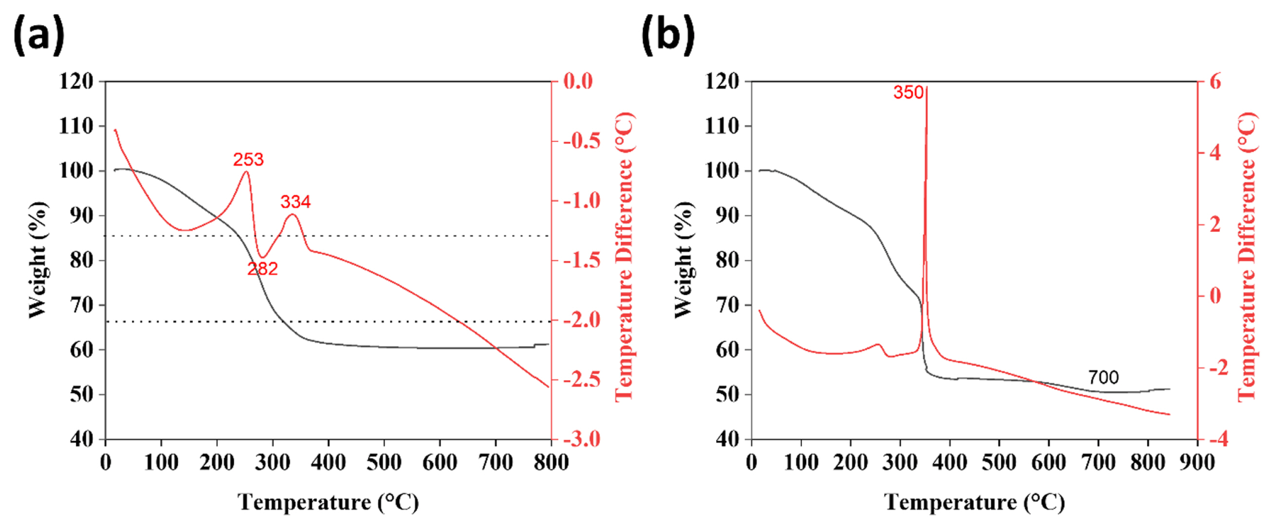
Based on optimal condition ŌĆ£7ŌĆØ for formulating the Ni0.91Co0.06Mn0.03CO3 precursor, we further formulated it on the cathode electrode active materials by mixing lithium hydroxide monohydrate (LiOH┬ĘH2O). To study the formation of Ni0.91Co0.06Mn0.03CO3 precursor through spray-drying and after treatment with hydroxide monohydrate, we examined the thermogravimetric (TG)-differential scanning calorimetry (DSC) analysis from room temperature (RT) up to 800┬░C. Furthermore, the obtained TG-DSC curves are shown in Fig. 5(a,b) for both cases. From Fig. 5(a), 20% of weight loss was observed from RT to 150┬░C for the Ni0.91Co0.06Mn0.03CO3 precursor, resulting from the dehydration of the initial nitrates. Moreover, a weight loss of 60% was observed in the range of 150ŌĆō350, indicating the decomposition of M (M=Ni, Co, Mn) carbonate [30]. Interestingly, we observe the clear high-temperature difference peak at 350┬░C, after treatment with lithium hydroxide monohydrate (Fig. 5(b)) contributing to the metal salt decomposition we expect. Combining the weight loss phenomenon observed in a range of 200ŌĆō400┬░C in Fig. 5(a,b), we can conclude the total weight loss of 50.5 wt% of the Ni0.91Co0.06Mn0.03CO3 precursor powder under treatment with the lithium hydroxide monohydrate.
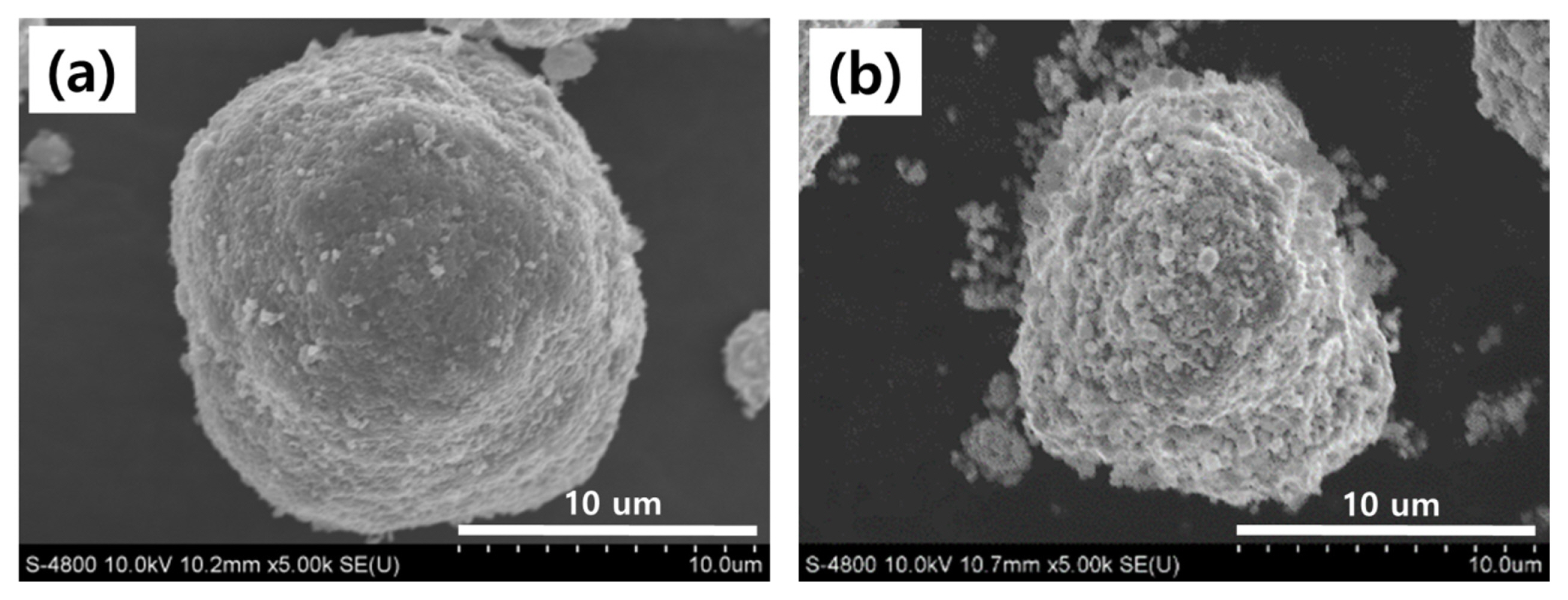
Fig. 6(a,b) shows the FE-SEM image of Ni0.91 Co0.06Mn0.03CO3 precursor powder (after treatment with the lithium hydroxide monohydrate), and cathode active material, which is sintered the precursor powder at 480┬░C for 5 hours and then sintered at 780┬░C for 15 hours under an oxygen atmosphere. From the FE-SEM observation, the spherical shape of the Ni0.91Co0.06Mn0.03CO3 precursor powders has not changed even after the longer sintering time. As shown in Fig. 6(b), the powder sample shows the secondary particles with a micro-sized distribution (10ŌĆō20 ╬╝m) which consists of numerous primary particles (400ŌĆō700 nm). Basically, a good spherical shape, homogeneous distribution, and dense structure result in high tap density, which leads to excellent electrochemical properties [31]. Our study also shows a spherical shape and homogeneous distribution, which is expecting the good electrochemical properties of our synthesis of active materials. The EDS mapping was also conducted to confirm the Ni, Co, and Mn, as shown in Fig. S1. The clear Ni, Co, and Mn peaks were observed in the EDS mapping images without any impurity peaks, indicating the advantage of the spray-drying process.
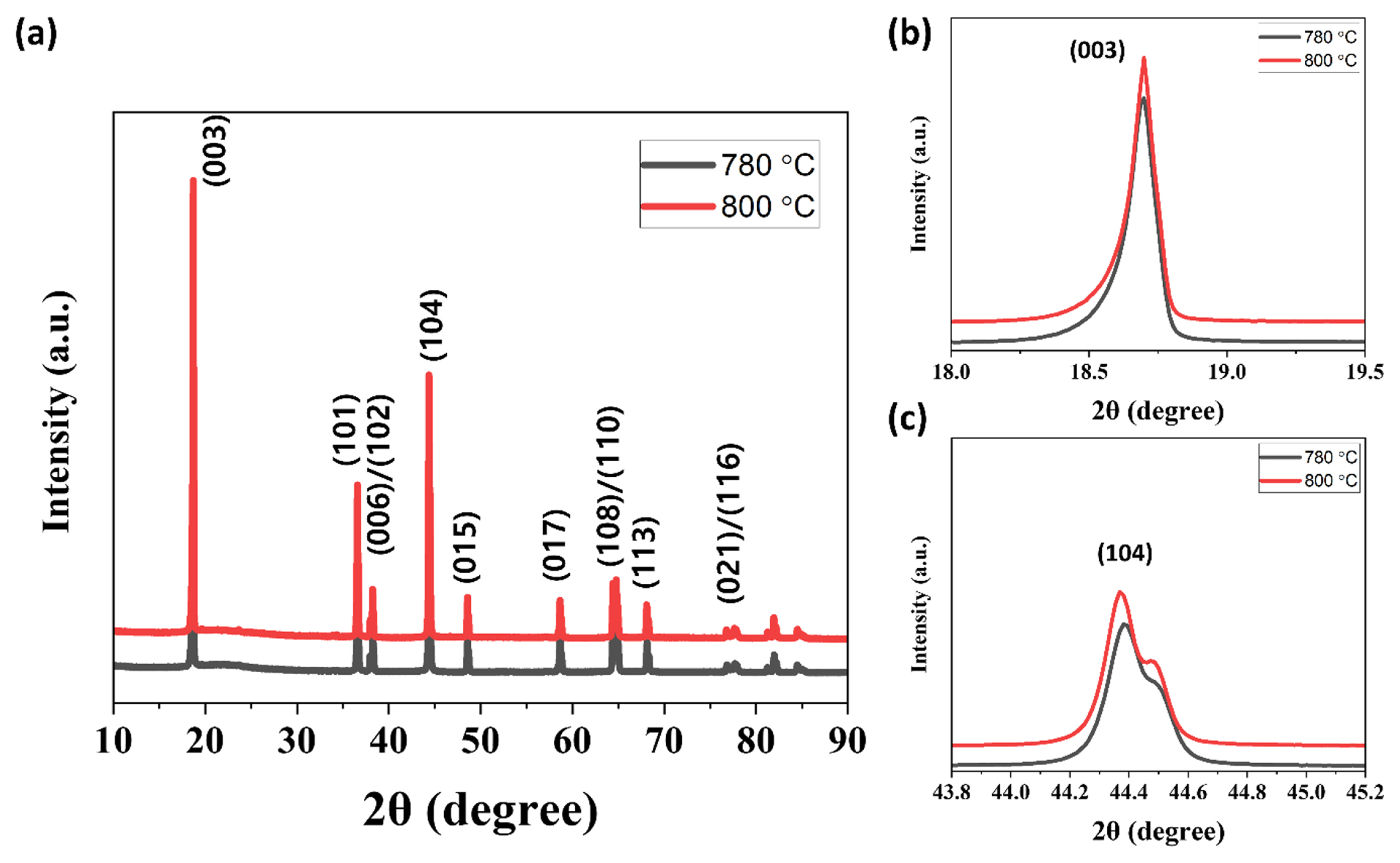
Fig. 7(aŌĆōc) summarizes the (a) XRD patterns and enlarged views of the (003) peaks, and (104) peaks of the LiNi0.91Co0.06Mn0.03O2 cathode active material sintered at 780 and 800┬░C. All peaks are indexed based on the layered hexagonal ╬▒ŌĆōNaFeO2 structure having R-3m space group which is similar to other research articles [31,32]. The clear splitting of 006/102 and 108/110 was observed in XRD spectra analysis as shown in Fig. S2(a,b), indicating the well-ordered layered structure with small cation mixing without secondary phase [24,33ŌĆō35]. Rietveld refinement is also conducted to calculate the lattice parameters and I(003)/I(104) ratio, as summarized in Fig. S3 and Table S1. The intensity ratios of I(003)/I(104) are 1.55 and 1.59 at 780 and 800┬░C showing a linear relationship between intensity and sintering temperature.
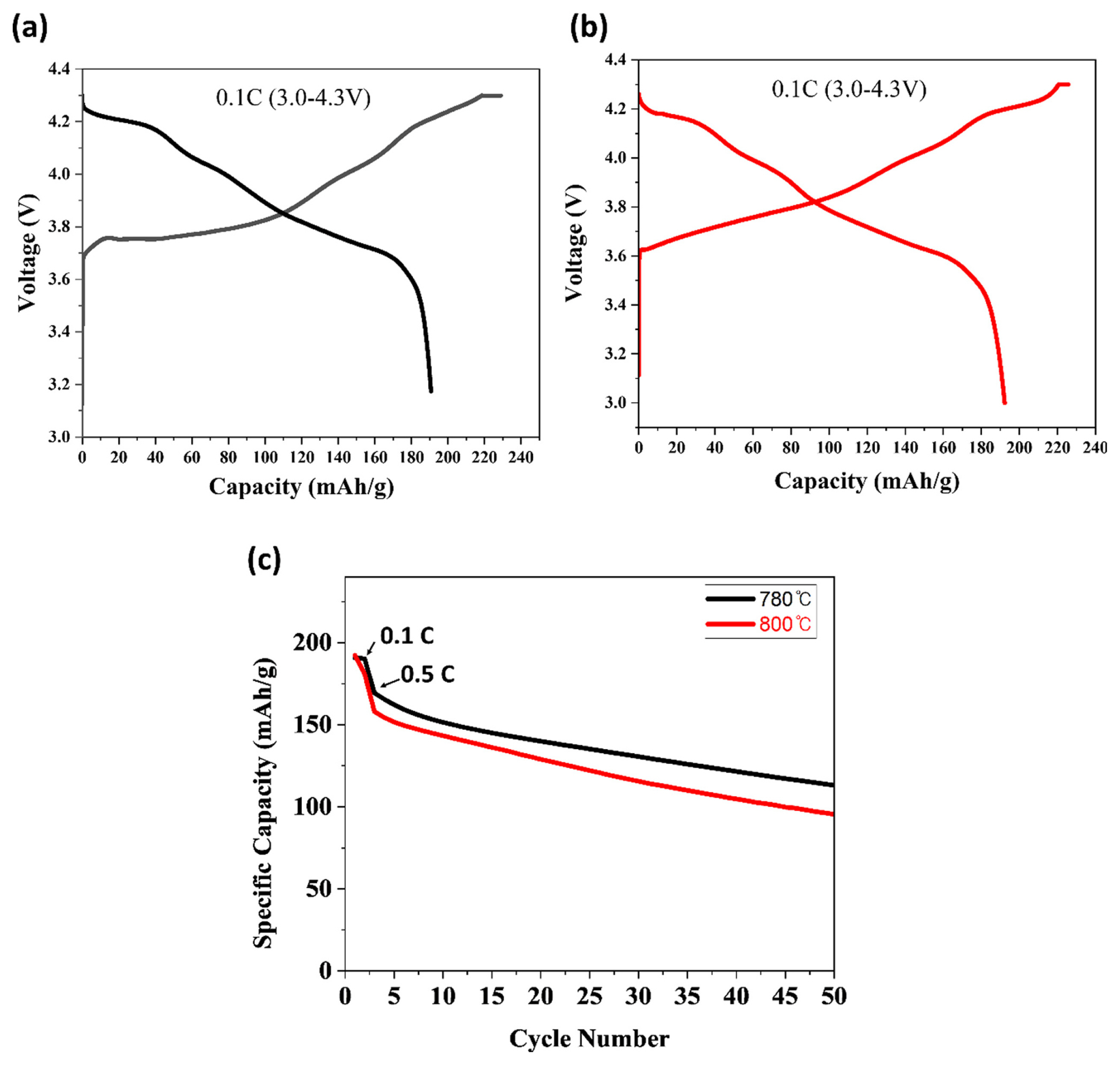
After sintering the LiNi0.91Co0.06Mn0.03O2 cathode active materials at two different temperatures (780 and 800┬░C) for 15 hours, we future assemble it with anode components as a coin cell type to conduct the electrochemical study. More detailed fabrication and electrical performance test method were described in the experimental section. Fig. 8(a,b) summarize the initial chargeŌĆōdischarge curves of NCM electrode which is made by LiNi0.91Co0.06Mn0.03O2 cathode active material with different sintering temperatures (780 and 800┬░C). The electrodes are cycled at 0.1 C (in first 2 cycles) and 0.5 C (after 2 cycles to 50 cycles) in the voltage range 3.0ŌĆō4.3 V, respectively. The dischargeŌĆōcapacity and the cycling performance results of NCM electrode are summarized in Table 2. As shown in Fig. 8, the voltage plateau was observed at 4.2 V, which is due to the high Ni ion concentration in the active materials [36]. The discharge capacity of both two samples is similar. However, the sample sintered at 800┬░C (LiNi0.91Co0.06Mn0.03O2 cathode active material) shows a slightly high discharge capacity of 192.3 mAh/g with Coulombic efficiency of 86.34%. On the other hand, the sample sintered at 780┬░C delivers 190.76 mAh/g with Coulombic efficiency of 83.37%. Therefore, the two sintering temperatures of 780 and 800┬░C used in the experiments do not significantly affect the initial charge-discharge capacity. However, the minute difference might be due to the slightly high cation mixing. Fig. 8(c) shows the variation in the cycling performance of NCM electrodes at 0.1 C (in first 2 cycles) and 0.5 C (after 2 cycles to 50 cycles) in the voltage range of 3.0ŌĆō4.3 V. Among two different sintering temperatures, the NCM sintered at 780┬░C delivers the capacity retention of 66.80% after 50 cycles. It can be explained by the rapid and durable electrochemical kinetics and excellent interfacial stability between the electrode/electrolyte. On the other hand, the NCM sintered at 800┬░C shows inferior cyclability (capacity retention 60.38%) compared to 780┬░C.
We thought the poor electrochemical performance of 800┬░C NCM is due to the sustained contraction and expansion of the lattice structure during cycling. These anisotropic volume changes lead to the generation of microcracks which permits deep penetration of electrolyte that results in the thick solid-electrolyte interphase (SEI) layer [31,32,37]. Moreover, weak spots of SEI layer can generate the localized lithium-ion flux causing dendritic growth problems or safety hazards during the electrochemical cycling [38]. Therefore, the optimum sintering temperature can suppress the adverse effects on the NCM by boosting structural stability. Since LiNi0.91Co0.06 Mn0.03O2 contains residual lithium such as LiOH and Li2CO3, which are released during the oxidation reaction process above 4 V, resulting in a decrease in initial Coulombic efficiency and cycle performances, this residual lithium side effect should be reduced by introducing effective methods. One possible process to improve the electrochemical performance of NCM is applying the gas-phase reaction method during the synthesis of high nickel-layered cathode materials to modify the residual lithium and, in turn, reduce the generation of LiOH and Li2CO3. Alternatively, it can improve performance via surface-modified cathode materials by coating with KCl, where the added KCl reduces residual lithium compounds such as LiOH and Li2O3 on the surface. Enhancing the electrochemical properties of active materials by reducing the Li was obtained from this study. In conclusion, this spraying drying process does not require additional pre-treatment steps, or coating of alien materials and thus can be simply fabricated into the cathode active materials, potentially expediting the development of high-energy-density batteries for applications in EVs.
4. Conclusions
In this study, Ni0.91Co0.06Mn0.03CO3 precursor was prepared firstly by spray-drying process using transition metal carbonates as raw material. LiNi0.91Co0.06 Mn0.03O2 cathode active material was successfully synthesized at different temperature (780 and 800┬░C) to optimize the sintering process. The spray-drying method, which is highly efficient, environment-friendly, and non-pollution, allowed us for good rheological properties and stability attributes in the final product. Considering the precursor droplet size, morphology, and yield from this study, we found optimal spray-drying operating conditions from condition 7 (Inlet-temp (┬░C): 190, Drying air flow rate (m3/h): 20, Atomizing air spray flow rate (L/h): 742, Feed flow rate (mL/min): 1.5). From the operating conditions test, ŌĆśatomizing air spray flow rateŌĆÖ, and ŌĆśfeed flow rateŌĆÖ were revealed to be the key parameters in our study. A higher atomizing air spray flow produces smaller droplets from the nozzle, and the corresponding solid particle size decreases. On the other hand, a higher feed flow rate can increase the droplet size because of large liquid dispersion.
In addition, we successfully synthesized the LiNi0.91Co0.06Mn0.03O2 cathode active materials with low Li+/Ni2+ disorder and high crystallinity using the Ni0.91Co0.06Mn0.03CO3 precursor. As a result, the NCM electrode, which is made by LiNi0.91Co0.06 Mn0.03CO3 cathode active materials, delivered discharge capacity of 190.76 mAh/g at 0.1 C and maintained 66.8% retention after 50 cycles. Because a market research company projects for the global battery industry expecting to grow at a compound annual growth of more than 10% up to 2027 [39], we hope the current work will contribute to the industrialization of NCM cathode materials applications.