


1. Introduction
Li[(Ni0.6Co0.1Mn0.3)0.36(Ni0.80Co0.15Al0.05)0.64)]O2 cathode materials have attracted wide interest as promising alternative cathode materials due to their high capacity, relatively low cost, and low toxicity compared with LiCoO2. However, in general, Ni-rich cathode materials with a layered structure commonly undergo structural degradation from the layered phase to the spinel-like and rock-salt phases during cycling and at elevated temperature [1,2,16-18]. This structural change is caused by migration of the transition metal (TM) ions into the lithium layer during charging and discharging. The TM ion migration leads to the layered-to-spinel phase transformation, and the transformation is intensified by high-voltage and high-temperature cycling because of the increasing number of vacant Li sites during full delithiation and due to the diffusion of TM ions. These phase transitions with TM-ion migration are accompanied by changes in the lattice constants and volume, which release oxygen from the lattice. This in turn can lead to thermal and structural instability [3]. Ni-rich cathode materials, commonly prepared by coprecipitation method, are composed of round-shape secondary particles in which many micrometer-sized primary particles (grains) are aggregated. Because these primary particles have different crystallographic orientations and slip planes, anisotropic lattice volume expansion or contraction between the grains during lithium intercalation or deintercalation results in microcracks that act as new reaction sites with the electrolyte, leading to electrical disconnection between the grains. As a result, a new solid electrolyte interface (SEI) layer, comprising decomposition products of the electrolyte, is formed along the active surface of the primary particles (grains) developed by the micro-cracks. The SEI layer on the surface of the grains inhibits electron and lithium transport through the grain–electrolyte interface, thus diminishing the electrical performance [3,4].
To resolve the structural and thermal instability of Ni-rich cathode materials, many researchers have implemented surface modification using inorganic materials such as Al2O3, ZrO2, AlPO4, and AlF3 [5-7]. Although inorganic coatings have been found to suppress the interfacial side reactions, the inorganic substances are discontinuously deposited on the cathode materials and also remain as an ionically/electronically resistive layer. As a consequence, faradaic reaction kinetics at the cathode material-liquid electrolyte interface could be impaired, overshadowing the advantageous effects of inorganic coatings. The complex coating process is another disadvantage. The surface modification of cathode materials with a conductive polymer is beneficial with respect to delivering the original capacity without a reducing the amount of the electrochemically active element in the parent cathode materials. Furthermore, the conductive polymer coating layer effectively suppresses the SEI film formation and HF attack by blocking the contact between the electrolyte and the cathode material. A simple coating methods has been reported by D.W. Kim and coworkers [8]. However, it is difficult to apply to the cathode material because of the high price of conductive polymers.
Polypropylene(PP) is one of the most attractive coating materials in terms of addressing these problems. It has low cost and offers high thermal stability, and flexibility. To the best of our knowledge, there are no published reports of PP coaing on cathode materials providing improved electrochemical properties. In this work, we synthesized Li[(Ni0.6Co0.1Mn0.3)0.36 (Ni0.80Co0.15Al0.05)0.64)]O2 cathode materials with high discharge capacity. Their surfaces were modified by coating with PP polymer in order to improve the electrochemical performance. Scanning electron microscopy (SEM), energy dispersive spectroscopy (EDS) mapping, atomic force microscope (AFM), transmission electron microscope (TEM), differential scanning calorimetry(DSC), and electrochemical tests were performed to explain and validate the results obtained with the proposed approach.
2. Experimental Section
2.1 Synthesis of Li[(Ni0.93Co0.07)0.36(Ni0.6Co0.2Mn0.2)0.64]O2
The precursor [(Ni0.6Co0.1Mn0.3)0.36(Ni0.85 Co0.15)0.64] (OH)2 was synthesized via co-precipitation. An aqueous solution of NiSO4·6H2O, CoSO4·7H2O and MnSO4·H2O with a concentration of 1 M was pumped into a 4 L continuously stirred tank reactor under N2 atmosphere. At the same time, NaOH (2 M) solution and NH4OH solution were separately fed into the reactor. During the co-precipitation reaction, the newly formed particles grew into spherical particles under vigorous stirring. In order to construct a core-shell material with a composition of [(Ni0.6Co0.1Mn0.3)0.36(Ni0.85 Co0.15)0.64](OH)2, the Ni0.6Co0.1 Mn0.3(OH)2 product was continuously mixed with the solution containing metal compounds (Ni:Co cationic ratio = 85:15). The resulting, [(Ni0.6Co0.1Mn0.3)0.36(Ni0.85 Co0.15)0.64](OH)2 particles were then filtered, washed, and dried in air or vacuum. Core precursors and LiOH·H2O were mixed at room temperature for 1 h. The core shell precursors, LiOH·H2O and Al(OH)3·H2O were mixed under the same conditions. The mixed powder was calcined at 800 ℃ for 24 h under an O2 flow.
2.2 Polypropylene coating
PP(Aldrich) powder was dispersed in xylene at a concentration of 0.1 wt%. The NCS powders were immersed in the polymer solution, and the mixture was stirred at 60 ℃ for 4h to induce surface coating of the NCS powders. After the mixed solution was filtered, followed by calcining at 150 ℃ for 12 h, surface coated NCS powders were finally obtained.
2.3 Electrochemical test
Samples were investigated via scanning electron microscopy (SEM QUANTA 300, JEOL) before and after coating. The elemental distribution of the surface of the coated NCS particles was examined using energy dispersive spectroscopy (EDS). The electrochemical performance was measured using a CR2032 coin type cell. The cathode was fabricated by blending the active material, super-P carbon, and the binder (8:1:1) in N-methyl-2-pyrrolodone. The mixed slurry was cast uniformly on a thin aluminum foil substrate and dried under a vacuum for 12 h at 120 ℃. A lithium metal foil was used as the anode. A polypropylene micro-porous film was used as the separator. The electrolyte was 1 M LiPF6 in a 3:7 (v/v) mixture of ethylene carbonate (EC) and diethyl carbonate (DEC). The cells were assembled in an argonfilled glove box. Electrochemical tests were performed between 3.0 and 4.3 V. AC impedance in the Li/NCS cells were measured in SOC (state of charge = 0) using a Solatron 1287 electrochemical interface over a frequency range of 1 Hz to 155 Hz with an amplitude of 10 μA.
3. Results and Discussion
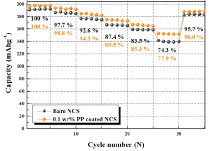
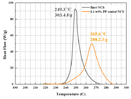
AFM images of bare and 0.1 wt% PP-coated NCS particles are shown in Fig. 1. From the 0.1 wt% PP-coated NCS particles, the average roughness was reduced from 34.3 nm to 28.6 nm. This means that the 0.1 wt% PP-coated NCS particles had a lower surface area than the NCS particle. Low surface area of the primary particles and indirect contact area between cathode and electrolyte is effective for reducing the contact area with the electrolyte. It will therefore be possible to reduce the chemical side reactions with the electrolyte. The chemical side reactions are among the unnecessary reactions. It is known that commercial LiPF6-based lithium battery electrolytes always contain a trace amount of water, and it has been established that LiPF6 can react with this water and produce a very reactive HF species. The surface of the cathode material is attacked by HF species from the electrolyte. The reaction causes elution of transition metal elution in the cycling process [9]. However, the PP coating reduces the contact with the electrolyte, and improvement of electrochemical properties is thus expected. In order to confirm the existence of the coated layer, Fig. 2 shows a TEM image of a 0.1 wt% PP-coated NCS particle. The edge of the 0.1 wt% PP-coated NCS particle is covered with a thin layer (average thickness = 8.43 nm) with uniform dispersion. The selected area electron diffraction (SAED) patterns were obtained from the PP-coated layer and the NCS cathode material. The SAED pattern corresponding to the PP-coated layer (right side) exhibited a hollow ring pattern without bright spots, thus indicating that the coated layer consisted of disordered polymer materials. The image in the right inset shows some bright spots in the SAED pattern, which is typical of crystalline NCS cathode material [2,8]. These results thus provide conclusive evidence that the NCS particles are uniformly coated by the nano-sized polymer layer. Fig. 3 shows Nyquist plots of the bare and 0.1 wt% PP-coated NCS electrode in the charged state of 4.3 V. The high-frequency semicircle is attributed to the resistance of the solid electrolyte interphase (SEI) film (RSEI), and the second semicircle that appears at lower frequency is associated with the charge transfer resistance (Rct) [10,11]. The SEI film is formed by contact between the oxygen generated in the charging process and the electrolyte. The reaction of generated oxygen with the electrolyte forms SEI film such as Li2CO3, ROLi, or ROCO2Li on the surface of the cathode material. The SEI film reduces the electrochemical properties that prevent lithium diffusion. The PP-coated layer present on the cathode material surface effectively reduces the contact between the oxygen and the electrolyte. The RSEI value of the 0.1 wt% PP-coated NCS electrode is smaller than that of the bare NCS electrode. With the reduced RSEI, the Rct of the 0.1 wt% PP-coated NCS electrode is lowered from 24.3 Ω to 15.1 Ω. Fig. 4 presents the initial charge and discharge curves of the cells with bare NCS and 0.1 wt% PP-coated NCS electrodes in a voltage range of 3.0 to 4.3 V at a constant current rate of 17 mA/g. The bare NCS cathode material coated with PP delivered a slightly higher discharge capacity (196.10 mAhg−1) than the bare NCS cathode material (190.67 mAh/g−1), and this is attributed to the effect of SEI film. In the case of the 0.1 wt% PP-coated NCS electrode, the Rct of the RSEI reduction decreases after the initial charge process. Therefore, the initial discharge capacity increase relative to the bare NCS electrode, and thus, when calculating initial efficiency based on the results, initial coulomb efficiency increases from 94.7 % to 96.2 %. Fig. 5 shows the cycle performance of bare NCS and 0.1 wt% PP-coated NCS electrodes at a current density of 17 mA/g between 3.0 and 4.3 V. The initial discharge capacity of the bare NCS electrode decreased from 190.67 mAh/g to 171.22 mAh/g after 40 cycles. (40th cycle efficiency = 89.8 %). The 0.1 wt% PP-coated NCS electrode delivered an initial discharge capacity of 196.10 mAh/g, which was reduced to 182.77 mAh/g after 40th cycle. (40th cycle efficiency = 93.2 %). The cycle efficiency is a result of suppressing the SEI film and HF attack, and the suppressed SEI film reduces the Rct. Furthermore, the insertion and extraction of Li+ ions proceeds smoothly in the charge and discharge process. The contact area undergoing HF attack is reduced. Therefore, it is possible to improve structural instability by reducing transition metals elution [12,13]. Fig. 6 shows the electrochemical properties of various current densities of the bare NCS and 0.1 wt% PP-coated NCS electrode. The PP-coated electrode exhibited a higher discharge capacity at all the rates compared with that of the bare electrode, further enhancing the rate capability. Polypyrole has been known as an inherent electrical conductive polymer due to the conjugation of the single and double bonds alternating within macromolecular architecture [14]. The extra electrons of the double bond in a conjugated system are free to move or roam through the polymer chain. Therefore, the superior rate performance of PP-coated electrode is obtained with the high electronic conductivity of polypyrole layer although reducing surface area. These results indicated an easier lithium intercalation/deintercalation owing to reduced charge transfer resistance [14,15]. Fig. 7 shows DSC curve of bare NCS and 0.1 wt% PP-coated NCS cathode materials in the charged state of 4.3 V. The bare NCS material had a large exothermic peak at 249.3 ℃ and the reaction released heat of 303.4 J/g. However, for the 0.1 wt% PP-coated NCS material, the reaction took place at a higher temperature of 265.6 ℃ with reaction released heat of 288.2 J/g. This indicates that the PP coating layer with high surface coverage effectively prevents the NCS from being directly exposed to the liquid electrolyte, which in turn alleviates the exothermic reaction between the delithiated NCS and liquid electrolyte. The similar DSC result of PATEP coated NCM cathode was published [19].
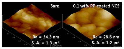
Fig. 2.
TEM image of 0.1 wt% PP-coated NCS particle with SAED patterns (left SAED pattern : cathode material, right SAED pattern : PP coating layer).
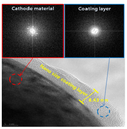
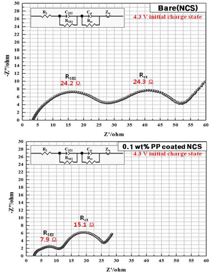
Fig. 4.
Initial charge and discharge graph of bare and 0.1 wt% PP-coated NCS electrodes at 17 mA/g rate between 3.0 V and 4.3 V.
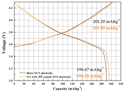
Fig. 5.
40th cycle performance of bare NCS and 0.1 wt% PP-coated NCS electrodes at current density 17 mA/g between 3.0 V and 4.3 V.

4. Conclusions
NCS cathode materials with high discharge capacity were synthesized and surface-modified by coating with polypropylene. The PP coating layer effectively reduced the SEI film that is generated after the 4.3 V initial charge process. RSEI consequently decreased due to the reduced SEI film. In addition, from the reduction of RSEI, lithium intercalation and deintercalation are improved and Rct is reduced. From these results, the initial charge/discharge efficiency of the 0.1 wt% PP-coated NCS electrode is higher (96.2 %) than 0 wt% PP-coated NCS electrode. Also, the 30th cycle efficiency was improved to 93.2 %. It was confirmed via a DSC analysis that the thermal stability of the 0.1 wt% PP-coated NCS material was improved by reducing the generated heat and an increasing the exothermic reaction.


