1. Introduction
Lithium-ion batteries are still the most widely used portable power sources in many applications like electric vehicles and portable devices due to their excellent electrochemical performance [1,2]. However, the high cost, low lithium content in EarthŌĆÖs crust, and safety issues linked to flammable and toxic organic-based electrolytes enforce the development of new types of devices. Use of sodium- or potassium-ion batteries is cheaper but is more hazardous because of the high reactivity of alkali metals [3]. Among various types of metal-ion batteries, aqueous zinc-ion batteries (ZIBs) attract outstanding research interest in recent decades due to their excellent safety and low cost as energy storage devices with satisfactory energy density [4ŌĆō6].
These aqueous systems combine zinc anodes, where the system Zn/Zn2+ possesses low oxidation potential (ŌłÆ0.762 V vs SHE) and high reversible electrochemical reaction with such types of cathode materials, as manganese oxides and vanadium compounds [7], Prussian blue analogues, cobalt oxides, and organic compounds [4].
Among them, Mn-based materials, especially manganese oxides, are the primary choice in ZIBs. MnO2 has obvious advantages, such as being nontoxic, low-cost, environmentally friendly, and easy to obtain, including nanostructured forms [8]. Many forms of manganese dioxide: ╬▒-MnO2 [9], ╬▓-MnO2 [10], ╬│-MnO2 [11], ╬┤-MnO2 [12], ╬╗-MnO2 [13] or spinel ZnMn2O4 [14] are successfully applied in ZIBs. However, the electrochemical performance of most Mn-based cathodes in zinc-ion systems suffers from unsatisfactory stability and incomplete capacity utilization of capacity due to manganese dissolution and structural transformation of oxides in electrolytes containing solely Zn2+. Therefore, they are still far from practical applications and demand further explorations.
In addition, the second group of zinc hybrid aqueous batteries is also extensively investigated. The difference between Zn-ion and Zn hybrid systems is that in the first case Zn2+ ions act as sole charge carriers in both cathode and anode, while hybrid systems use two types of ions as charge carriers: for example, dissolution/deposition of zinc occurs on anode, simultaneous with intercalation/deintercalation of Li+ ions on cathode.
Commercially available cathode materials based on LiFePO4, LiNi1/3Mn1/3Co1/3O2 and LiMn2O4 (LMO) are particularly interesting cathode materials for aqueous electrolytes. All these materials were successfully applied in lithium-ion batteries [15ŌĆō18] and later showed good electrochemical properties in aqueous hybrid lithium-zinc systems [19ŌĆō21].
Spinel type LMO is one of the possible cathodes for hybrid lithium-zinc-ion batteries [19,20,22ŌĆō24], which shows fast insertion of lithium ions and solid-state diffusion of Li+ in the LMO lattice when used in aqueous electrolyte. Several investigations demonstrated that LMO cathode is operational in zinc-containing aqueous electrolytes like mixture of zinc and lithium sulfates [22,25] or acetates [17] and the reversible processes of lithium intercalation into the LMO structure and zinc plating/stripping on the anode occur. One of the approaches to enhance the electrochemical properties of LMO-cathodes is changing the electrolyte composition. Many types of aqueous electrolytes were reported: addition of indifferent salts that form complexes with zinc ions [19], highly-concentrated solutions (or ŌĆ£water-in-saltŌĆØ electrolytes) [24] or gel-polymer electrolytes [23].
However, in previous reports LMO electrodes have not been studied as possible candidate for prospective host materials for zinc-ion batteries. The zinc ions intercalation capability and possible transformation of LMO into Zn-containing phases were not considered. Therefore, the typical electrolytes for manganese oxide-based cathodes for aqueous zinc-ion batteries were scarcely investigated. This topic is of research interest, considering the number of recent observations made for other manganese oxide materials.
For example, the use of Mn2+ additives in electrolytes for manganese oxides-based cathodes in a zinc-ion system was employed for the suppression of Mn2+ dissolution, which resulted in enhanced cycling stability and capacity increase [26ŌĆō30]. Earlier reports show improvement of the electrochemical performance of LMO in conventional lithium-ion batteries after treatment in Zn-containing aqueous solution [31] which resulted in a decrease of specific capacity, but an enhancement of cycling stability. The highly reversible phase transformation between spinel ZMO and ╬╗-MnO2 upon Zn2+ insertion/extraction was also shown in [32] by in situ XRD investigation. Further exploration is required for understanding the effects of electrolyte on the electrochemical performance of LMO electrodes for ZIBs. As it is well-known, ╬╗-MnO2 also forms in LMO electrodes during the charging process, therefore similar transformation of structures in Zn2+ containing electrolytes can be expected. Nevertheless, there are no reports about electrochemical performance of LMO-based cathodes in zinc-containing electrolyte without lithium salt or with manganese salt additive.
In this paper, we present the results of the investigation of electrochemical performance of LMO as a potential cathode for aqueous zinc batteries in different electrolytes: zinc sulfate electrolyte (2MZnSO4), lithium-zinc sulfate electrolyte (1MZnSO4/2MLi2SO4) and lithium-zinc-manganese sulfate electrolyte (1M ZnSO4/2 M Li2SO4/0.1 M MnSO4). The purpose of using pristine zinc sulfate electrolyte was to investigate the possibility of electrochemical conversion of LMO spinel into Zn-containing phase. A process of phase transformation in Zn2+ containing electrolytes upon concomitant Zn2+ insertion/extraction was expected, as it was reported for ╬╗-MnO2 [32] and we intended to prove this hypothesis.
Additive of manganese sulfate into standard Li-Zn sulfate electrolyte was also tested for LMO at first time with the aim to increase the cycling stability of lithium manganese spinel.
Electrochemical behavior of the systems with various electrolytes was studied by cyclic voltammetry and galvanostatic charge-discharge at varied current densities. To the best of our knowledge, this is the first report on the electrochemical properties of LMO cathodes in lithium-free zinc- and ternary lithium-zinc-manganese aqueous electrolytes.
2. Experimental
LMO powder was purchased from MTI Corp. (USA). Conductive carbon black additive was purchased from Timcal Inc. (Belgium). Polyvinylidene fluoride (PVDF) and N-methylpyrrolidone were purchased from Aldrich. Lithium, zinc, and manganese sulfates were obtained from LenReactiv (Russia). All reagents were used as received except for LMO, which was dried in vacuum at 130┬░C.
Electrode material was prepared in accordance with conventional technique in the ratio 80 wt.% of LMO, 10 wt.% of carbon black, and 10 wt.% of PVDF. First, PVDF was dissolved in an appropriate volume of N-methylpyrrolidone, and then LMO and carbon black were added and mechanically mixed for 1 h. The resulting slurry was cast on the stainless-steel mesh and dried in vacuum at 80┬░C over 12 h. After that, the working electrodes were made by roll pressing. Average mass loading of LMO was approximately (4ŌĆō5) mg┬ĘcmŌłÆ2.
Electrochemical characteristics of the electrodes were measured in a three-electrode cell with stainless steel foil and Zn foil as counter and reference electrodes, respectively. The two-electrode cell configuration was used with LMO cathode and Zn foil anode. Four types of aqueous electrolytes were used (Table 1). Galvanostatic charge discharge (GCD) and cyclic voltammetry (CV) measurements were performed in the (1.4ŌĆō2.1) V (vs Zn/Zn2+) potential range on Elins 20X8 multichannel potentiostat/galvanostat. GCD were carried out in the (0.2ŌĆō5) C current range (current 1 C is equivalent to 115 mA gŌłÆ1) and CVs were measured at (0.1ŌĆō0.5) mV sŌłÆ1 scan rates.
The structure of the electrodes after the electrochemical tests was characterized by X-ray diffract ion measurements (XRD, Bruker-AXS D8 DISCOVER, Germany) using Cu K╬▒ radiation. Morphology of the materials was investigated by scanning electron microscopy (SEM, SUPRA 40VP, Carl Zeiss, Germany). EDX elemental analysis of samples and Zn element mapping was performed.
OriginPro software was used for data analysis. Scientific color map batlow [33] was used to prevent visual distortion of the data and exclusion of readers with color-vision deficiencies.
3. Results and Discussion
Evolution of CV curves for ten consecutive cycles in two different electrolytes (E1 and E2) in a (1.4ŌĆō2.1) V vs Zn/Zn2+ potential range is shown in Fig. 1aŌĆōd. LMO-electrode in combined electrolyte E2 showed two pairs of well-defined peaks corresponding to the electrochemical reaction of lithium intercalation (Fig. 1a) [34]. It is a typical CV pattern that is observed for the spinel-based electrodes in aqueous electrolytes with lithium sulfate. No visible effect on the magnitude and stability of the peaks was observed in the presence of Zn2+ ions in the electrolyte, indicating that zinc ions do not compete with lithium ions in the intercalation process in this case.
Anodic current at the most positive potentials decreases to almost background (zero) values, which indicates the absence of noticeable currents related to the oxygen evolution reaction (OER). This observation is in agreement with data presented in [14,35], where the onset of OER due to the decomposition of water molecules in the electrolyte proceeded just over 2.1 V (for 2M ZnSO4). Furthermore, cyclic voltammograms of LMO-electrode measured in extended potential range (Eup = 2.2 V vs. Zn/Zn2+) demonstrated insignificant increase of current at high potentials that can be ascribed to OER (Fig. S1).
After transferring the electrode from electrolyte E2 to pure ZnSO4 electrolyte E1, the initial two high anodic peaks (1.80 V and 1.93 V) with substantial specific capacity, maintained by the remaining lithium ions in the lattice, were observed only in the first cycle. In the following cycles, both anodic and cathodic peaks drop quickly along with the cycle number and almost vanish in several cycles (Fig. 1b).
When cycling of the LMO electrode starts in E1 electrolyte (Fig. 1c), two peaks are likewise visible on the anodic curve of the first cycle. However, there are no peaks on the cathodic one and at the following cycles. It clearly demonstrates that zinc ions cannot be extracted from the LMO crystal lattice reversibly. Nevertheless, the addition of lithium salt in the electrolyte (i.e., transferring the electrode into electrolyte E2, Fig. 1d) partially recovered this process, as initially present peaks reemerge during the following 5ŌĆō8 cycles, indicating regained electrochemical activity. However, there was an incomplete recovery of capacity, which is due to the surface presence of trapped/adsorbed Zn2+ ions blocking the internal active sites of LMO.
In the case of pure Li2SO4 electrolyte (E4) CV curves of LMO are presented in Fig. S2. In this case LMO acts as cathode material for lithium-ion batteries and this shape of curve is in full agreement with literature data, for example, for 2 M Li2SO4 aqueous solution [15].
EDX mapping of zinc element (Fig. S3) shows that its amount on the electrode after testing in electrolyte E1 is ten times higher than after electrochemical measurements in electrolyte E2 (27 wt.% and 2 wt.%, respectively, see Tables S1 and S2 for more details). Moreover, in both cases zinc distribution over the electrode surface is uniformly random. This supports the conclusion that possible trapped/adsorbed Zn2+ ions are blocking the surface of LMO electrode. In addition, amounts of manganese on the electrode surface is also dependent on the electrolyte composition: it is higher in the electrode tested in electrolyte E2 in three times (Table S1, S2). Amounts of all other main elements (oxygen, carbon, fluorine) is slightly varied for two different electrolytes.
Ex situ SEM-images of LMO-electrodes after cycling test in electrolytes E1 (Fig. S4a) and E2 (Fig. S4b) are also provided in Supplementary Information. Smoother surface of the electrode after electrochemical testing in E2 electrolyte was observed in Fig. S5b. The surface of LMO electrode after cycling in E1 electrolyte (solely ZnSO4) reveals some additional morphology features: the surface is covered by rough flaky structures that probably resulted from the transformation of surface structure upon Zn ions insertion.
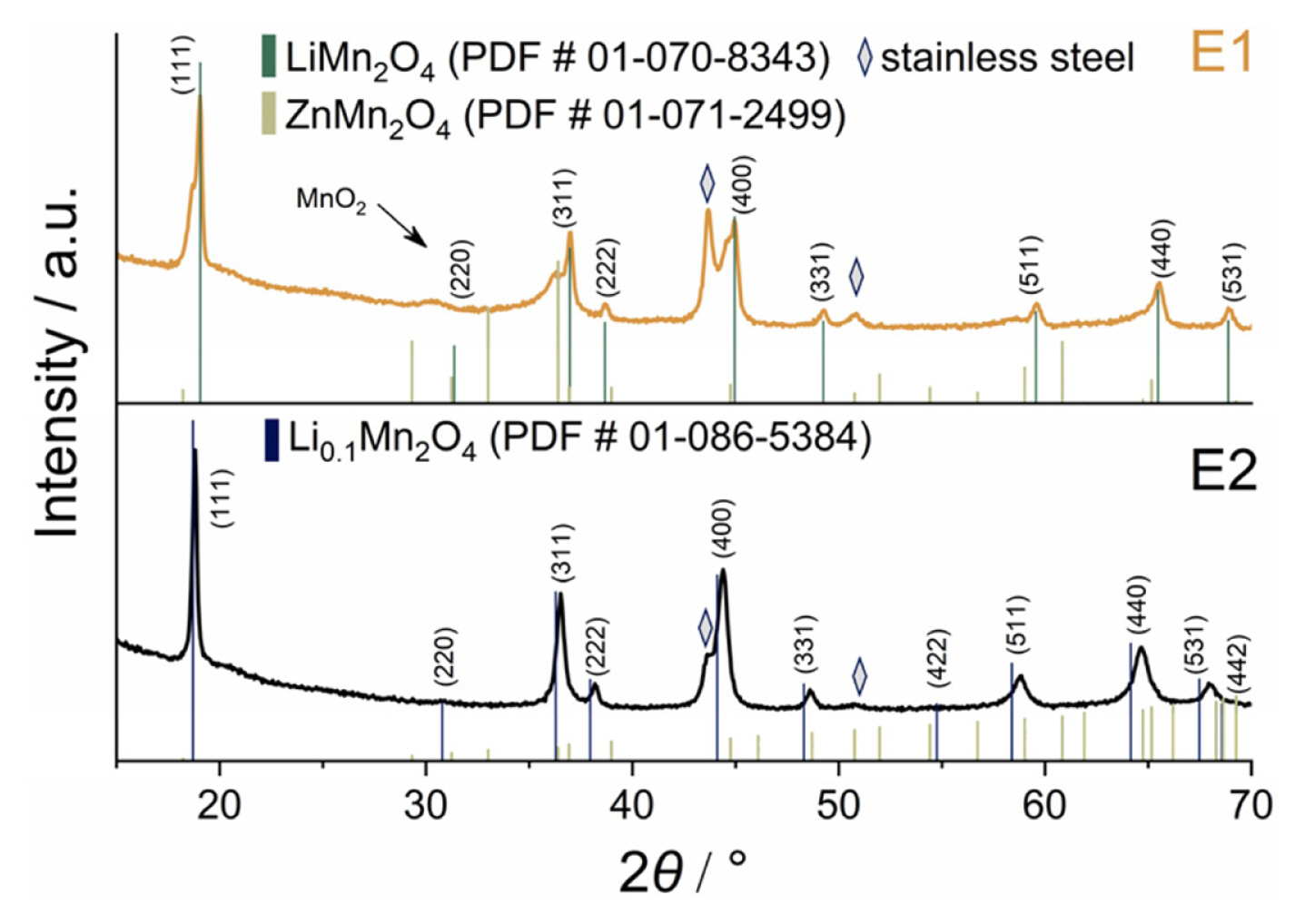
After CV tests, the cells were disassembled, and XRD patterns of the electrodes were obtained. It is clearly seen that the electrode which was lastly tested in electrolyte E2 has only one structural phase of LiMn2O4 (Fig. 2). Small shifts of the peaks, especially those related to (511), (440), and (531) crystal edges (at 58.34┬░, 64.09┬░ and 67.41┬░, respectively) are associated with the fixed position of LMO crystals in the composite electrode, which decreases the random distribution of the crystal edge, or may be linked to various degrees of lithium intercalation [36]. A delithiated Li0.1Mn2O4 phase is ascribed to the electrode cycled in E1 electrolyte. Moreover, a weak signal at 30.43┬░ might correspond to the ╬╗-MnO2 admixture phase, which is the final product of the electrochemical transformation of LiMn2O4 during the charge process. No emerging peaks were found on XRD pattern after cycling in Zn-containing electrolyte. We did not detect the peaks that could be unambiguously attributed to ZnMn2O4 phase, according to its card (ICCD PDF # 01-071-2499). The expected diffraction peaks at 29.32┬░, 33.01┬░ and 60.83┬░ are missing, yet in the case of E1 there is visible splitting of (111), (311) and (400) peaks. This does not allow to state conclusively that ZnMn2O4 forms yet implies some degree of phase transformation.
Thus, based on CV, XRD and EDX data, we found that zinc ions cannot replace lithium ones to form mixed phase ZnxLiyMn2O4 in which reversible processes of Zn insertion/extraction could occur as it was shown for ╬╗-MnO2 in [32]. A partially formed Zn-containing phase has no electroactivity which leads to a decrease of electrochemical properties as reported for highly concentrated ŌĆ£water-in-saltŌĆØ acetate electrolyte [20]. This dissimilarity in electrochemical behavior of LMO electrodes could be explained by different amount of coordinated water molecules. Zn2+ ions in (1ŌĆö2) M ZnSO4 solution have a hydrate shell consisting of 3 to 4 water molecules [37], while decreased coordination numbers in ŌĆ£water-in-saltŌĆØ electrolytes are known to suppress side reactions involving water and facilitate intercalation [38].
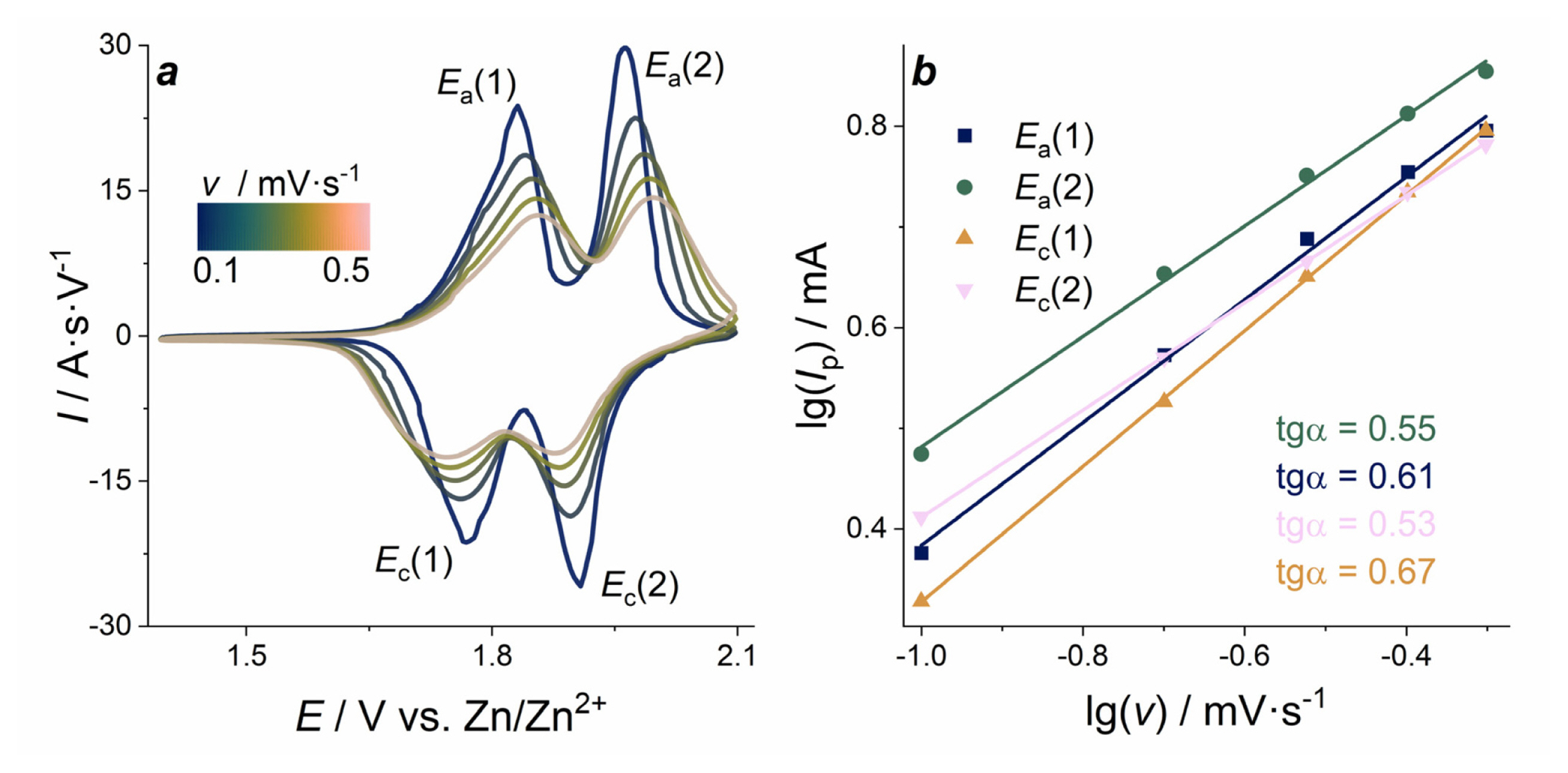
The electrochemical kinetics of LMO electrode was investigated by CV analysis with varied scan rates in the 0.1 mV sŌłÆ1 to 0.5 mV sŌłÆ1 range. CVs normalized by scan rate are presented in Fig. 3a. With the increase of the scan rate, the peak separation steadily increases from ╬öE1(0.1 mV sŌłÆ1) = 0.06 V to ╬öE1(0.5 mV sŌłÆ1) = 0.10 V for the leftmost pair of peaks, and from ╬öE2(0.1 mV sŌłÆ1) = 0.05 V to ╬öE2(0.5 mV sŌłÆ1) = 0.12 V for the more positive pair of peaks. Furthermore, the peaks become wider with the increase of the scan rate. This can be explained by the increase of ohmic resistance and kinetic limitation of charge/discharge processes.
Peak current plotted as a function of scan rate in double logarithmic coordinates (Fig. 3b) shows that the values of slope vary within the 0.53ŌĆō0.67 range. Based on general terms, the current response includes both diffusion-controlled reactions and capacitive effects, and the experimental data will obey the empirical equation, in which the peak currents are a power function of scan rate:
where Ip - peak current, ╬Į - scan rate, b - the exponent. This equation can be rewritten in logarithmic form:
When the b value is close to 0.5, ion diffusion limits the current of the electrochemical process. If the b value is close to 1.0, it indicates the current control by the surface electrochemical reaction. The values observed in the case of LMO electrode in E2 electrolyte are close to the characteristic value 0.5, indicating that the currents are mainly controlled by the diffusion limiting step of charge transport with the insignificant contribution of surface processes.
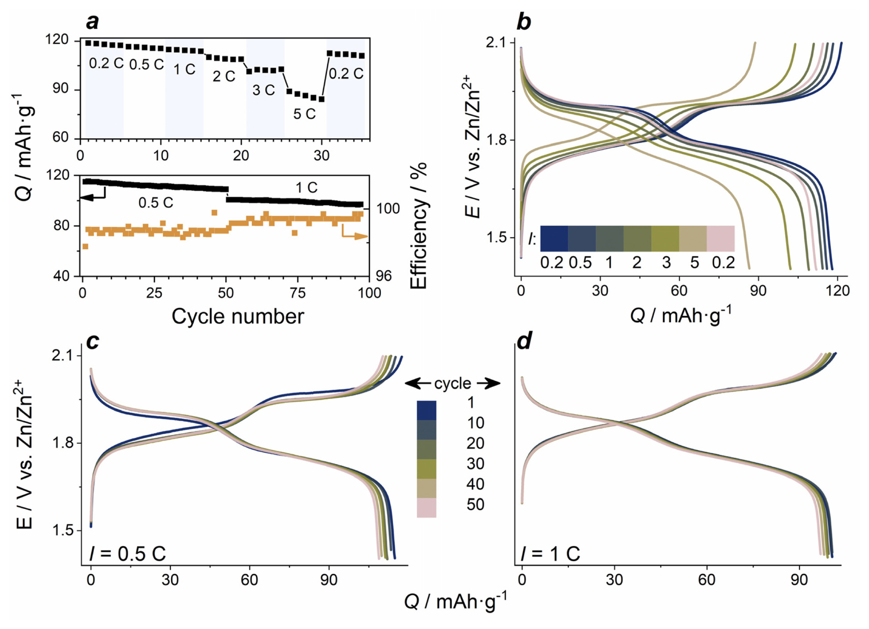
Electrochemical performance of LMO-electrodes in electrolyte E2 is presented in Fig. 4.
Charge/discharge curves of LMO electrodes at a constant current density of 0.5 C contain two characteristic charge and discharge potential plateaus corresponding to the intercalation/deintercalation of lithium ions into/out of the LMO spinel structure. The values of electrode potentials 1.89 V and 1.77 V related to discharge plateaus agree with CV peak potentials. The GCD curves display remarkable stability of the electrodes during continuous cycling, and the polarization in terms of the difference between the upper charge and the lower discharge plateau is almost unchanged. With the increase of the number of cycles, the shape of GCD curves is well preserved. The initial capacities of the electrodes are close to 120 mAh gŌłÆ1 at a low current density of 0.2 C, and 110 mAh gŌłÆ1 at 1 C. This is on par with similar reported multi-component electrolyte systems, e.g. 121 mAh gŌłÆ1 at 0.05 C and 90 mAh gŌłÆ1 (potassium/lithium/zinc acetate ŌĆ£water-in-saltŌĆØ) [20], 125 mAh gŌłÆ1 at 0.2 C (lithium/zinc sulfate for Zn/V2O5 battery) [39].
C-rate dependencies of GCD curves are shown in Fig. 4a,b. With the increase of current density from 0.2 C to 5 C, a gradual decrease of discharge specific capacity from 120 mA gŌłÆ1 to 86 mA gŌłÆ1 is observed, and the polarization visibly increases at higher C-rates. The main effect of higher current density on the capacity decrease is related to the shortened first discharge plateau, which is due to the incomplete charge of LMO electrode at the second electrode process (at 1.9 V). Capacity retention during 100 total cycles at 0.5 C (50 cycles) and 1 C (50 cycles) is 85% (Fig. 4c,d).
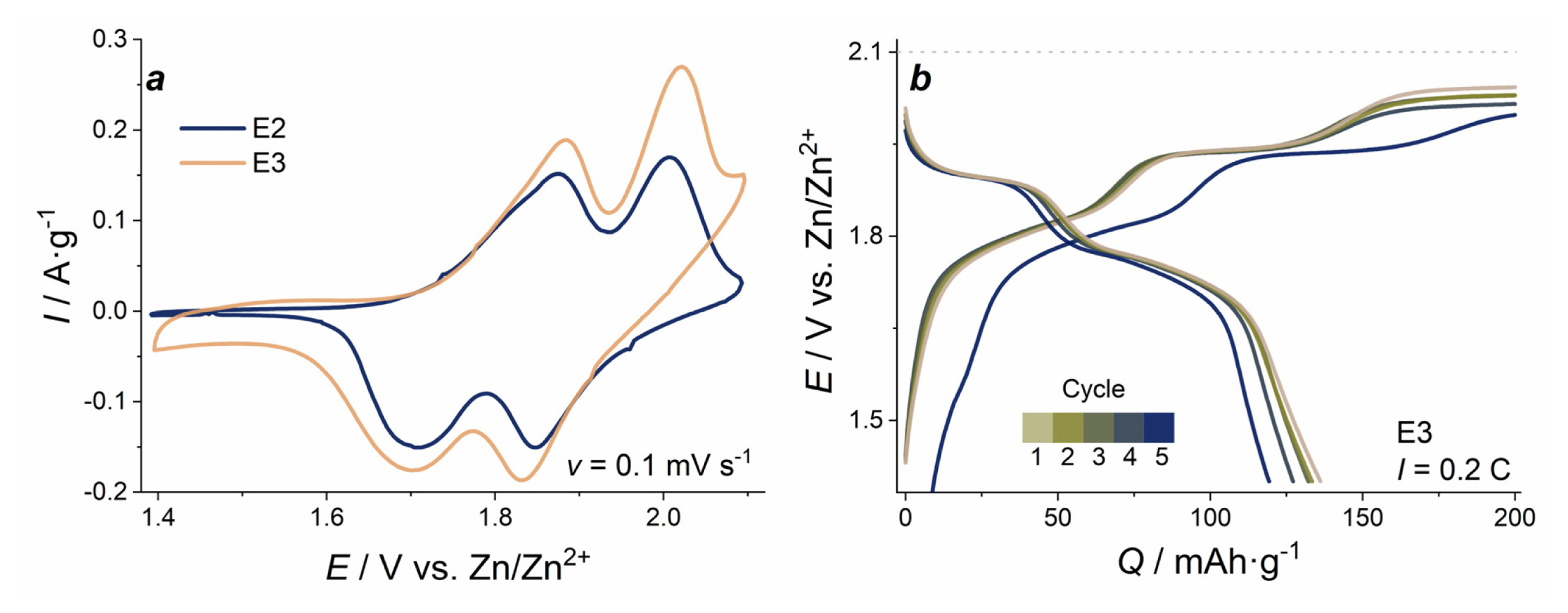
We observed the increase of peak current and a visible elevation of the anodic branch at most positive potentials on the CVs of LMO in the electrolyte E3: 1 M ZnSO4/2 M Li2SO4/0.1 M MnSO4 (Fig. 5a). It can be related to Mn2+ oxidation and MnOx layer formation on the electrode surface, which contributes to recharging processes [40]. From the GCD curves (Fig. 5b), it is seen that an additional plateau appears at the charging process at 2.03 V, which can be assigned to the oxidation of Mn2+ ions from the solution with the formation of additional MnOx surface layers. The observation of such oxidation process was also demonstrated previously for Zn//MnO2 cells at low current densities in the similar mixed electrolytes containing Mn2+ ions [28]. This third plateau disrupts the balance of 100% coulombic efficiency observed for the two first plateaus for the (1.4ŌĆō2.0) V range due to the extra charge in the (2.0ŌĆō2.1) V range. Higher initial values and an increase of specific capacity at first cycles cannot be attributed to the original mass of LMO. Instead, it is linked to the formation of additional electroactive material (manganese oxide) on the surface of LMO.
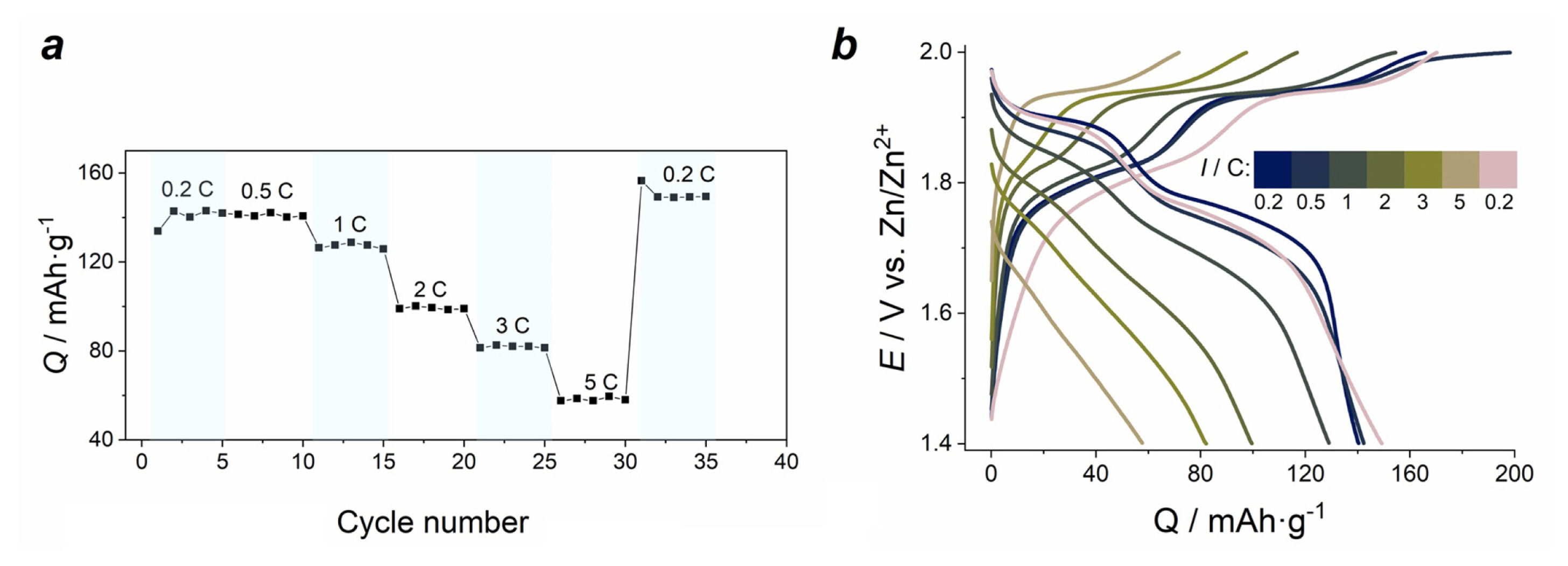
Because of that excessive oxidation of the E3 electrolyte component, we cut off the upper potential at 2.0 V for the subsequent GCD measurements (Fig. 6b). In this case we observed that the initial capacity of LMO-electrodes is higher than for those cycled in electrolyte E2. At low current (0.2 C and 0.5 C), the capacity of LMO is 140 mAh gŌłÆ1, and it drops more significantly at high current densities (86 mAh gŌłÆ1 in electrolyte E2, and 57 mAh gŌłÆ1 in E3 at 5 C). Nevertheless, the capacity value at constant discharge current is more stable than for the electrode cycled in electrolyte E2. Polarization increases by 25% at 1 C and rises further as current density grows. Discharge plateaus at (2ŌĆō5) C almost disappear. Incidentally, upon the return to 0.2 C, the capacity of the material is slightly higher (149 mAh gŌłÆ1) than the initial value (140 mAh gŌłÆ1).
These observations indicate that the addition of Mn2+ into the electrolyte facilitate to maintenance of capacity and slightly improve the cycling stability of LMO electrodes as it observed in other reports for aqueous zinc-ion batteries cathodes consisting of various MnO2 structural forms in (1.0ŌĆō1.9) V potential range [31,41]. Possibly, intercalation of zinc ions into emerging MnOx layer due to the addition of Mn2+ into the electrolyte leads to changes in the surface crystal structure of LMO. Postmortem XRD pattern of LMO electrode after electrochemical tests (Fig, S6) shows that crystal lattice of LMO was preserved but become more amorphous. However, the hypothesis of LMO surface crystal transformation needs further detailed study by sensitive structural methods, e.g., operando XRD spectroscopy or TEM.
4. Conclusions
Electrochemical properties of LiMn2O4 as a possible cathode material for aqueous zinc batteries were investigated in lithium-free zinc- and lithium-zinc-manganese containing electrolytes in comparison with behavior in standard electrolyte 1 M ZnSO4/2 M Li2SO4 for hybrid Li/Zn battery. It was shown that LMO is electrochemically inactive after the first oxidation cycle in pure ZnSO4 electrolyte. Structural characterization of postmortem electrodes with use of XRD and EDX analysis confirmed that the traces of Zn-containing phase are appeared in pure ZnSO4 electrolyte. It leads to fast capacity fading which is probably related to blocked electroactive sites. So, the hypothesis about possible phase transformation of LMO into structures with reversible zinc intercalation in aqueous ZnSO4 was not confirmed.
The initial capacity of LMO is higher in presence of MnSO4 (140 mAh gŌłÆ1 at 0.2 C in 1 M ZnSO4/2 M Li2SO4/0.1 M MnSO4 and 120 mAh gŌłÆ1 at 0.2 C in 1 M ZnSO4/2 M Li2SO4). Capacity increase can be explained by the electrodeposition of MnOx layer on the electrode surface. The electrolyte with manganese additive (Mn2+) enhances the cycling stability of LMO-electrodes.